PowerBridge cPCIS-6235R Series User manual

cPCIS-6235R Series
2U Height Sub-System for
6U cPCI and Components
User’s Guide

Table of Contents
x
i
Table of Contents
How to Use This Manual
................................................................ii
1Introduction ....................................................................................1
1.1 Product Definition ......................................................................1
1.2 Features.....................................................................................1
1.3 Mechanical Drawing ..................................................................3
1.4 Available Models........................................................................4
1.5 Customized Systems.................................................................4
2Getting Started ..............................................................................5
2.1 Shipping Contents ......................................................................6
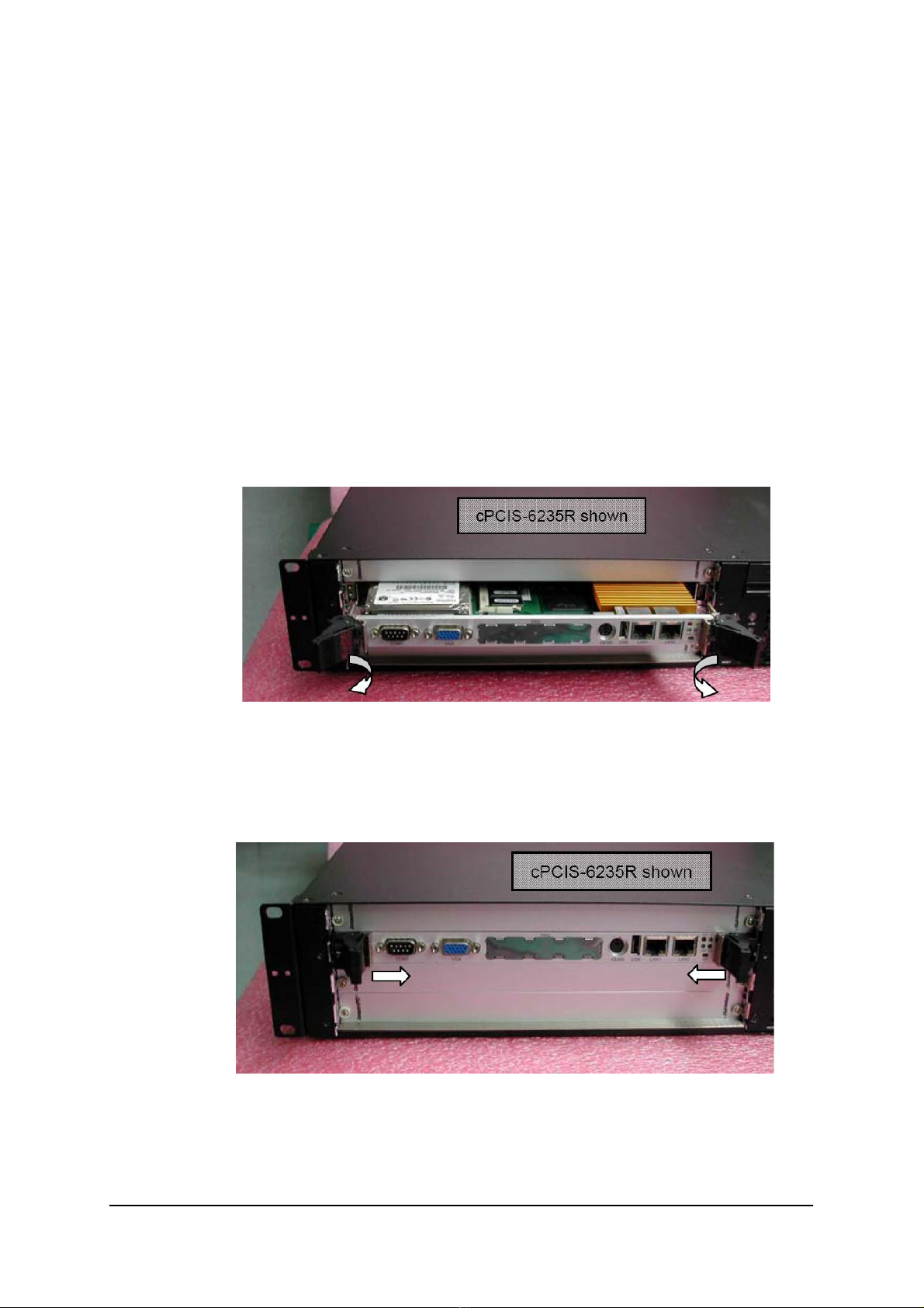
2.2 CompactPCI Card Installation ...................................................5
2.3 Rear Transition Module (RTM) Installation.................................8
2.4 Powering Up the System............................................................8
3Backplane Connectors .................................................................9
3.1cBP-6103R ...............................................................................10
3.2cBP-6403R ...............................................................................24
3.3cBP-6403R/N110......................................................................38
4Cooling Fans.................................................................................51
4.1 Removing and Replacing the Air Filter....................................51
4.2 Mechanical Drawing ................................................................52
4.3 Specifications...........................................................................53
5Power Supply Unit .......................................................................54
5.1 R2A-6300P ...............................................................................54
6 System Alarm Board....................................................................58
7 Specifications...............................................................................61
Important Safety Instructions
...................................................62
Warranty Policy
...............................................................................64

ii
x
How to Use This Manual
This manual is designed to help you use the cPCIS-6235RSeries 6U
CompactPCI Sub-system. It is divided into six chapters:
Chapter 1: Introduction, gives an overview of the product features.
Chapter 2: Getting Started, describes the unpacking procedure, setup
and configuration of the sub-system.
Chapter 3: Backplane Connectors, gives a detailed description of the
backplanes used in the cPCIS-6235R Series sub-
systems.
Chapter 4: Cooling Fans, describes the fans used to cool the sub-
system and how to remove and replace the sub-system air
filter.
Chapter 5: Power Supply Unit, describes the PSU of the cPCIS-
6235R Series sub-systems.
Chapter 6: System Alarm Board, monitoring inner chassis
temperature,fan status.
Chapter 7: Specifications, describes the sub-system’s detailed
specifications,

Introduction
x
1
1Introduction
1.1 Product Definition
The cPCIS-6235R Series sub-systems are designed for 6U cPCI boards
with 80mm RTMs and are suitable for computer telephony applications.
The chassis is 2U height and standard 19” rack mount width.
The cPCIS-6235R series have a PICMG 2.1 Hot Swap compliant 32/
64-bit 3-slot CompactPCI backplanes and a PICMG 2.5 H.110 CT Bus.
1.2 Features
General
x19” Rackmount, 2U height for 6U cPCI boards with 80mm rear I/O
xSuitable for one dual-slot system module with two expansion boards
xStandard 6U CompactPCI and PICMG 2.5 H.110 CT Bus
xPICMG 2.1 Hot Swap compliant 32/64-bit 3-slot CompactPCI backplane
with P3&P5 rear I/O
xBuilt-in 300W+300W Dual AC-input mini redundant power supply
xBuilt-in expansion board for one internal 2.5” HDD and one external IDE device
xRedundant cooling architecture with monitoring LED
xAlarm module for chassis temperature and fan status monitoring
xLED indicators for power statusfan statustemperature alarm
xGuarded power switch and alarm reset button

2
x
Introduction
Boards Space
xBoard space supports standard 6U height and 3-slot width
xBoth front access and rear access are possible
CompactPCI Compliancy
xPICMG 2.0 CompactPCI core specification R3.0
xPICMG 2.1 CompactPCI hot swap R2.0
xPICMG 2.5 CompactPCI Computer Telephony R1.0 (optional)
Enclosure
xEIA RS-310C 19” 2U height rackmount enclosure
xCoated metal plate outer covering

Introduction
x
3
1.3 Mechanical Drawing
Chassis Front View
Chassis Rear View (AC in)
Chassis Front View
Chassis Real View

4
x
Introduction
1.4 Available Models
The cPCIS-6235R Series comes in the following models:
xcPCIS-6235R- 32-bit, 3-slot, AC in PSU
xcPCIS-6235R/64 - 64-bit, 3-slot, AC in PSU
xcPCIS-6235R/64/N110- 64-bit, 3-slot, w/o H.110 bus, AC in PSU
xcPCIS-6235R/DC - 32-bit, 3-slot, DC in PSU
xcPCIS-6235R/64/DC - 64-bit, 3-slot, DC in PSU
xcPCIS-6235R/64/N110/DC - 64-bit, 3-slot, w/o H.110 bus, DC in PSU
1.5 Customized Systems
Sub-systems can also be customized to meet individual needs. To
customize a sub-system please contact an ADLINK dealer. For complete
systems, users must order CPU modules in addition to the sub-system.

Getting Started
x
5
2Getting Started
In this chapter, we will describe the unpacking procedure of the sub-system
and installation procedure of the hard drive and CompactPCI cards.
2.1 Shipping Contents
Check the shipping carton for any damage. If the shipping carton and
contents are damaged, please notify the dealer for a replacement. Retain
the shipping carton and packing material for inspection by the dealer. Obtain
authorization before returning any product to ADLINK.
Check that the following items are included in the package. If there are any
missing items, please contact your dealer:
xOne cPCIS-6230R or cPCIS-6240R sub-system
xThis User’s Manual
xAccessory Package: includes power cords for 110V and 220V wall
sockets, replacement air filter, ergonomic rackmount handles, and
pouch containing screws, zip ties, etc..

Getting Started
x
6
2.2 CompactPCI Card Installation
CompactPCI connectors are rigid, and therefore require careful handling
when inserted and removed. Improper manipulation of the cards will result in
damage to the backplane.
System slots usually have some obvious indicators, something like red card
guide rail, triangle mark enclosing the slot number on the backplane. The
system card only can be installed in the system slot, and do not insert system
card into any other slot, or insert any peripheral card into system slot.
The handles on CompactPCI card helps users to install or remove easily and
safety. Please follow the procedures below to install a CompactPCI module
into a chassis:

7
x
Getting Started
CompactPCI Card Installation Procedure
1. Place the sub-system on a level surface or rackmount it. Remove the
blanking plates where required by undoing the retaining screws at each
end. Retain the blanking plates for possible future use. The system
should not be put into use without blanking plates for all empty slots,
otherwise the EMC and cooling performance will be compromised
2. Hold the SBC module or peripheral card horizontally. Make sure that
the handles are unlatched (i.e. that they are spread outwards). If
necessary, unlatch the handle by pressing on the release button with
your thumb.
3. Carefully insert the module into the desired slot by sliding the edges of
the board into the appropriate card guide rail. Take care to ensure
correct alignment of the card with the chassis during insertion to prevent
damage to the card and/or backplane.
4. Continue inserting the card until the handles engage with the chassis.
5. Pull inwards on the handles for final insertion. Ensure that the red
buttons on the handles fully latch into position as unless this is done the
card is not correctly inserted.
6. To remove the module, press the red release buttons, and reverse
steps 1 through 5 above.

Getting Started
x
8
2.3 Rear Transition Module (RTM) Installation
The installation and removal procedures for RTMs are the same as for
CompactPCI cards. Since RTMs are shorter than the CompactPCI cards,
they require more careful handling during installation and removal.
Note: We strongly recommended the use of RTMs with AB type connectors
to prevent the damage to the backplane during RTM installation.
2.4 Powering Up the System
Before connecting the power cord to the system, make sure the AC-in power
switch is in the O(off) position (see Section 1.3, Mechanical Drawing,
Chassis Rear View).
The cPCIS-6230R/40R sub-systems feature a guarded power switch and
reset button that provide ATX power control capability. Use the tool provided
in the Accessory Packet or a suitably shaped object (such as a pen) to
actuate the power switch and reset button.
power switch
reset button
Voltage Indicato
r
LEDs

Backplane
x
9
3Backplane Connectors
In this chapter, we will describe the backplanes for the cPCIS-6235R Series.
The following list outlines the backplanes that correspond to each model.
Model* Type Backplane
cPCIS-6235R 32-bit, 3-slot cBP-6103R
cPCIS-6235R/64 64-bit, 3-slot cBP-6403R
cPCIS-6235R/64/N110 64-bit, 3-slot cBP-6403R/N110
* The DC input versions of the corresponding models have the same backplane.

10
x
Backplane
3.1 cBP-6103R
The backplane for the cPCIS-6235R 6U 32-bit, 3-slot chassis is the
cBP-6103R, a 6U 3-slot H.110 32-bit CompactPCI backplane with rear I/O.
Mechanical Drawing
rP4 rP5
rP3
V (I/O)
IDE Connectors
cBP-6103R Rear View
P1
P2
P3P4 (H.110 CT Bus)P5
System
Slot
cBP-6103R Front View
System
Slot

Backplane
x
11
Features
xStandard CompactPCI 2U height for 6U cPCI cards
xSupport 80mm rear I/O for each slot
xSuitable for one dual-slot system module with two expansion cards
xSupport PICMG 2.5 H.110 CT Bus
xPICMG 2.1 Hot Swap compliant 32-bit 3/4-slot CompactPCI
backplane with P3&P5 rear I/O
xSupport one 40pin IDE channel and one 34pin FDD channel
Specifications
xCompactPCI Compliancy
oPICMG 2.0 CompactPCI core specification R3.0
oPICMG 2.1 CompactPCI hot swap R2.0
oPICMG 2.5 CompactPCI Computer Telephony R1.0
xDimension: 279.2 x 81 (mm, W x H)
xPCI bus clock: 32-bit/33MHz
xSystem slot rear I/O: P3,P4 and P5 rear I/O with AB type shroud
xPeripheral slots: two
xH.110 bus: Compliant with PICMG 2.5, for all peripheral slots
xV (I/O): 3.3V or 5V selectable, default 5V
xPower Connectors: ATX connector x1
xSystem slot legacy I/O: FDD, IDE1 (pin compatible with cPCI-6760D
and cPCI-6780 only)
xOther connectors: INH#, Reset, PWR_FAL#, Voltage LEDs

12
x
Backplane
Pin Assignment
¾CN1 - ATX Power Connector
PIN SIGNAL PIN SIGNAL
1 +3.3V 11 +3.3V
2 +3.3V 12 -12V
3 GND 13 GND
4 +5V 14 PS_ON_L
5 GND 15 GND
6 +5V 16 GND
7 GND 17 GND
8 POWER
GOOD
18 -5V
9 5V STB 19 +5V
10 +12V 20 +5V
¾CN2 - Reset Button
Pin # Signal Name
1 PRST#
2 Ground
¾CN3 - ATX Power Switch
Pin # Signal Name
1 INH#
2 Ground
3 DEG#
¾CN4 - CT Power
Pin # Signal Name
1 -SEL Vbat
2 SEL VbatRtn
3 VRG
4 VRGRtn
5 -Vbat
6 VbatRtn
1 11
1
1
1

Backplane
x
13
¾CN5 - Floppy Drive Connector
Signal Name PIN # PIN # Signal Name
Ground 1 2 Drive density selection
Ground 3 4 No connect
Ground 5 6 Drive density selection
Ground 7 8 Index
Ground 9 10 Motor enable 0
Ground 11 12 Drive select 1
Ground 13 14 Drive select 0
Ground 15 16 Motor enable 1
Ground 17 18 Direction
Ground 19 20 Step
Ground 21 22 Write data
Ground 23 24 Write gate
Ground 25 26 Track 00
Ground 27 28 Write protect
Ground 29 30 Read data
Ground 31 32 Side 1 select
Ground 33 34 Diskette change

14
x
Backplane
¾CN6 - IDE Drive Connector
Signal Name Pin # Pin # Signal Name
Reset IDE 1 2 Ground
Host data 7 3 4 Host data 8
Host data 6 5 6 Host data 9
Host data 5 7 8 Host data 10
Host data 4 9 10 Host data 11
Host data 3 11 12 Host data 12
Host data 2 13 14 Host data 13
Host data 1 15 16 Host data 14
Host data 0 17 18 Host data 15
Ground 19 20 N.C
DRQ0 / DRQ1 21 22 Ground
Host IOW 23 24 Ground
Host IOR 25 26 Ground
IOCHRDY 27 28 Host ALE
DACK0 / DACK1 29 30 Ground
IRQ14 / IRQ 15 31 32 No connect
Address 1 33 34 No connect
Address 0 35 36 Address 2
Chip select 0 37 38 Chip select 1
Activity 39 40 Ground
¾FAN1/FAN2/FAN3/FAN4/FAN5 - Fan power connector
Pin # Signal Name
1 NC
2 +12v
3 Ground
¾JP1 - Shelf Enumeration Bus signals
Pin # Signal Name Pin # Signal Name Pin # Signal Name
1 NC 2 SGA0 3 Ground
4 NC 5 SGA1 6 Ground
7 NC 8 SGA2 9 Ground
10 NC 11 SGA3 12 Ground
13 NC 14 SGA4 15 Ground
1
1 3
513

Backplane
x
15
¾JP2 - M66EN (short 33MHz, open 66MHz, default setting: short)
Pin # Signal Name
1 M66EN
2 Ground
¾J1/J2/J3 - V (I/O), default: +5V
Pin # Signal Name
1 NC
2 +12v
3 Ground
¾J4 - +3.3V LED connector
Pin # Signal Name
1 +3.3V VCC
2 Ground
¾J5 - +5V LED connector
Pin # Signal Name
1 +5V VCC
2 Ground
1
1
1

16
x
Backplane
¾J6 - +12V LED connector
Pin # Signal Name
1 +12V VCC
2 Ground
¾J7 - -12VLED connector
Pin # Signal Name
1 Ground
2 -12V VCC
¾S1/S2/S3 - Peripheral/System Slot P5
Pin Z A B C D E F
22 GND NC NC NC NC NC GND
21 GND NC NC NC NC NC GND
20 GND NC NC NC NC NC GND
19 GND NC NC NC NC NC GND
18 GND NC NC NC NC NC GND
17 GND NC NC NC NC NC GND
16 GND NC NC NC NC NC GND
15 GND NC NC NC NC NC GND
14 GND NC NC NC NC NC GND
13 GND NC NC NC NC NC GND
12 GND NC NC NC NC NC GND
11 GND NC NC NC NC NC GND
10 GND NC NC NC NC NC GND
9 GND NC NC NC NC NC GND
8 GND NC NC NC NC NC GND
7 GND NC NC NC NC NC GND
6 GND NC NC NC NC NC GND
5 GND NC NC NC NC NC GND
4 GND NC NC NC NC NC GND
3 GND NC NC NC NC NC GND
2 GND NC NC NC NC NC GND
1 GND NC NC NC NC NC GND
Pin Z A B C D E F
1
1

Backplane
x
17
¾S4/S5 - Peripheral Slot P4
Pin Z A B C D E F
25 GND SGA4 SGA3 SGA2 SGA1 SGA0 GND
24 GND GND GND NP GND NP GND
23 GND +12V /CT_RST GND -12V CT_MC GND
22 GND PFS0# NP NP NP NP GND
21 GND -SEL Vbat PFS1# NP NP SEL VbatRtn GND
20 GND NP NP NP NP NP GND
19 GND NP NP NP NP NP GND
18 GND VRG NP NP NP VRGRtn GND
17 GND NP NP NP NP NP GND
16 GND NP NP NP NP NP GND
15 GND -Vbat NP NP NP VbatRtn GND
12-14 Key
11 GND CT_D29 CT_D30 CT_D31 V(I/O) /CT_FRAME_A GND
10 GND CT_D27 +3.3V CT_D28 +5V /CT_FRAME_B GND
9 GND CT_D24 CT_D25 CT_D26 GND /FR_COMP GND
8 GND CT_D21 CT_D22 CT_D23 +5V CT_C8_A GND
7 GND CT_D19 +5V CT_D20 GND CT_C8_B GND
6 GND CT_D16 CT_D17 CT_D18 GND CT_NETREF_1 GND
5 GND CT_D13 CT_D14 CT_D15 +3.3V CT_NETREF_2 GND
4 GND CT_D11 +5V CT_D12 +3.3V SCLK GND
3 GND CT_D8 CT_D9 CT_D10 GND SCLK-D GND
2 GND CT_D4 CT_D5 CT_D6 CT_D7 GND GND
1 GND CT_D0 +3.3V CT_D1 CT_D2 CT_D3 GND
Pin Z A B C D E F
This manual suits for next models
6
Table of contents
Popular Power Supply manuals by other brands

Pulsar
Pulsar AWZ 333 Installation and operating manual

VOLTCRAFT
VOLTCRAFT SPS12-60W operating instructions

Liebert
Liebert 311 Installation, operation & maintenance manual

SELF Electronics
SELF Electronics SLT6-350ISC-UN Instructions for the use

BEL
BEL TET3000-12-069RA Installation instruction

Monacor
Monacor PS-500XC quick guide