manuals.online logo
Brands
  1. Home
  2. •
  3. Brands
  4. •
  5. NETGEAR
  6. •
  7. Power Supply
  8. •
  9. NETGEAR RPS4000v2 User manual

NETGEAR RPS4000v2 User manual

Installation Guide
Check the LEDs
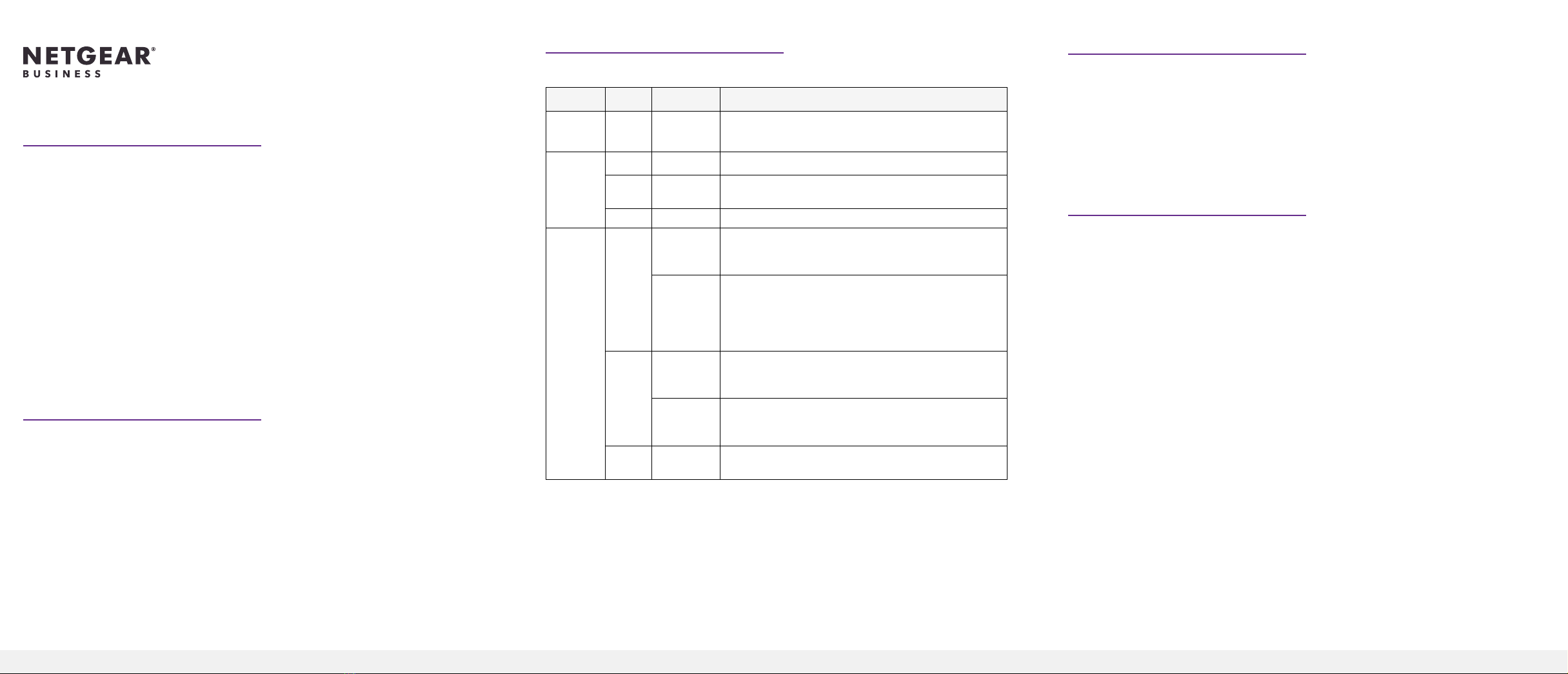
Power system indicators are listed in the following table:
Label Color Activity Description
PWR
(Power)
Green On Power is being provided to the RPS4000v2.
Power
Module
Status
Green On An APS1000W is present and working properly.
Yellow On An APS1000W is present but is not working
properly.
Off Off There is no APS1000W present.
RPS Port
Status
Green On The switch supports dynamic power allocation, and
the APS1000W in the corresponding RPS port and
power module bay is supplying power to the switch.
Blinking The switch supports dynamic power allocation, but
the APS1000W in the corresponding RPS port and
power module bay is not supplying power to the
switch. Power is being supplied by the APS1000W in
a different power module bay.
Yellow On The switch does not support dynamic power
allocation, and the APS1000W is providing power to
the switch.
Blinking The switch does not support dynamic power
allocation, but the APS1000W is not supplying
power to the switch.
Off Off No power is being supplied to the switch, or the
switch is not recognized.
Redundant Power System and Power Bank
Model RPS4000v2
The Redundant Power System and Power Bank RPS4000v2 provides power
system redundancy to external devices such as NETGEAR chassis switches,
managed switches, or smart switches with an RPS capability.
Each RPS4000v2 includes four power module bays, and can provide a maximum
output of 4000W when four APS1000W power supply units (PSU) are installed.
The RPS4000v2 can supply power to devices that support dynamic power
allocation as well as to legacy devices. The RPS4000v2 acts as a redundant power
system in 12 VDC context and acts as a power bank in PoE (56 VDC) context.
Package Contents
This package includes:
• Redundant Power System and Power Bank RPS4000v2
• AC power cable
• RPS cable, 60 cm (23.6 in.),16 pin
RPS ports
Each RPS port on the RPS4000v2 can provide a maximum of 1440W at 56 VDC
and 200W at 11 VDC. Output power depends on the number of power supply
units (PSU) installed, and the settings of the Type selector and Current Share (CS)
selector on the back panel of the RPS4000v2.
To determine the RPS type for other switches, see the hardware installation guide
,which you can download by visiting netgear.com/support/download/.
Install the RPS4000v2
Install the RPS4000v2 in a standard 19-inch rack.
WARNING: Do not stack equipment, or place equipment in tight spaces or in
drawers. Be sure that your equipment is surrounded by at least 2 inches (5 cm) of
air space.
Insert a power supply unit
In models with more than one PSU, the PSUs are hot-pluggable.
1. If your switch functions with a single PSU only, disconnect the power cord
from the PSU and let the switch power down.
If your switch functions with more than one PSU, you do not need to power
down the switch and you can perform a hot swap.
2. Remove the PSU from the power module bay by moving the orange release
latch to the left and pulling the extraction handle.
3. Insert the replacement PSU into the power module bay, and gently push the
PSU into the bay until the latch locks.
CAUTION: When inserting the PSU, do not use unnecessary force. Doing so
can damage the connectors on the back of the PSU and on the midplane.
4. Connect the end of the power cord to the power receptacle on the PSU.
NETGEAR, Inc.
350 East Plumeria Drive
San Jose, CA 95134, USA
NETGEAR INTERNATIONAL LTD
Floor 1, Building 3
University Technology Centre
Curraheen Road, Cork,
T12EF21, Ireland
© NETGEAR, Inc., NETGEAR and the NETGEAR Logo
are trademarks of NETGEAR, Inc. Any non‑NETGEAR
trademarks are used for reference purposes only.
March 2020
To install the RPS4000v2:
1. Attach the supplied mounting brackets to the side of the RPS4000v2.
2. Use the provided Phillips head screws to fasten the brackets to the sides of
the RPS4000v2.
3. Tighten the screws with a No. 1 Phillips screwdriver to secure each bracket.
4. Align the bracket and rack holes. Use two pan-head screws with nylon
washers to fasten each bracket to the rack.
5. Tighten the screws with a No. 2 Phillips screwdriver to secure the switch in
the rack.
Check the installation
Before you apply power, perform the following checks:
1. Inspect the equipment thoroughly.
2. Verify that all cables are installed correctly.
3. Check cable routing to ensure that cables are not damaged and do not
create a safety hazard.
4. Be sure that all equipment is mounted properly and securely.
Connect a switch to the RPS4000v2
WARNING: To prevent an electrical hazard, make sure that the RPS AC power
cord is not connected to the RPS before you install an APS1000W PSU or connect
the RPS to a switch.
1. Make sure an APS1000W PSU is installed into the power module bay on the
RPS4000v2.
2. Connect a switch to the corresponding RPS port.
3. Based on the RPS specication for the switch, set the position for the Type
and CS selectors on the back panel of the RPS4000v2. See the RPS4000v2
Hardware Installation Guide for conguration instructions.
4. Connect the switch to the RPS port on the RPS4000v2 using a NETGEAR RPS
cable (60 cm, 16 pin).
5. Power on the APS1000W that is connected to the switch.
Specications
Technical Specications
RPS port interface 4 NTGR RPS ports, 16 pin
Power 100–240 VAC, 50–60 Hz
Dimensions (H x W x D) 1.7 x 17.32 x 16.92 in. (43 x 440 x 430 mm)
Weight 12.8 lbs (5.8 kg)
Operating temperature 0° to 50°C (32° to 104°F)
Operating humidity 90% maximum relative humidity, noncondensing
Safety agency
approvals
UL, LVD, CB
Support and Community
Visit netgear.com/support to get your questions answered and access the latest
downloads.
You can also check out our NETGEAR Community for helpful advice at
community.netgear.com.
Regulatory and Legal
Si ce produit est vendu au Canada, vous pouvez accéder à ce document en
français canadien à https://www.netgear.com/support/download/.
(If this product is sold in Canada, you can access this document in Canadian
French at https://www.netgear.com/support/download/.)
For regulatory compliance information including the EU Declaration of
Conformity, visit https://www.netgear.com/about/regulatory/.
See the regulatory compliance document before connecting the power supply.
For NETGEAR’s Privacy Policy, visit https://www.netgear.com/about/privacy-policy.
By using this device, you are agreeing to NETGEAR’s Terms and Conditions at
https://www.netgear.com/about/terms-and-conditions. If you do not agree, return
the device to your place of purchase within your return period.

Other manuals for RPS4000v2

2

Other NETGEAR Power Supply manuals

NETGEAR PSU XCM88PS1 Manual

NETGEAR

NETGEAR PSU XCM88PS1 Manual

NETGEAR APS150W User manual

NETGEAR

NETGEAR APS150W User manual

NETGEAR APS135W - ProSafe Auxillary Power Supply User manual

NETGEAR

NETGEAR APS135W - ProSafe Auxillary Power Supply User manual

NETGEAR APS150W User manual

NETGEAR

NETGEAR APS150W User manual

NETGEAR EPS90W User manual

NETGEAR

NETGEAR EPS90W User manual

NETGEAR APS525W - ProSafe 525W Auxillary Power... User manual

NETGEAR

NETGEAR APS525W - ProSafe 525W Auxillary Power... User manual

NETGEAR XSM7224S - ProSafe 10 Gigabit Stackable User manual

NETGEAR

NETGEAR XSM7224S - ProSafe 10 Gigabit Stackable User manual

NETGEAR ProSafe APS1000W User manual

NETGEAR

NETGEAR ProSafe APS1000W User manual

NETGEAR RPS4000v2 Manual

NETGEAR

NETGEAR RPS4000v2 Manual

NETGEAR RPS4000v2 Manual

NETGEAR

NETGEAR RPS4000v2 Manual

NETGEAR APS250W User manual

NETGEAR

NETGEAR APS250W User manual

NETGEAR APS150W User manual

NETGEAR

NETGEAR APS150W User manual

Popular Power Supply manuals by other brands

3B SCIENTIFIC PHYSICS 1008692 instruction sheet

3B SCIENTIFIC PHYSICS

3B SCIENTIFIC PHYSICS 1008692 instruction sheet

bonitron M3545P Reference manual

bonitron

bonitron M3545P Reference manual

Placid Industries PS-12 manual

Placid Industries

Placid Industries PS-12 manual

Westermo PS-260 manual

Westermo

Westermo PS-260 manual

Ulvac SEREM PSE-150C instruction manual

Ulvac

Ulvac SEREM PSE-150C instruction manual

Bpt XA/301LR manual

Bpt

Bpt XA/301LR manual

Velleman HQ Power PSS6EMV28 user manual

Velleman

Velleman HQ Power PSS6EMV28 user manual

IBM 11000 VA LCD 5U Rack Installation Instructions

IBM

IBM 11000 VA LCD 5U Rack Installation Instructions

VOLTCRAFT 2264184 operating instructions

VOLTCRAFT

VOLTCRAFT 2264184 operating instructions

Aplab VSP1060 instruction manual

Aplab

Aplab VSP1060 instruction manual

Monacor PSS-1005USB manual

Monacor

Monacor PSS-1005USB manual

Akyga AK-L1-150 user manual

Akyga

Akyga AK-L1-150 user manual

SEIS EP8 user manual

SEIS

SEIS EP8 user manual

MPE DP SERIES II Operating and service manual

MPE

MPE DP SERIES II Operating and service manual

nextys NPSM20 Series instruction manual

nextys

nextys NPSM20 Series instruction manual

PowerBox Systems GEMINI II instruction manual

PowerBox Systems

PowerBox Systems GEMINI II instruction manual

HP 59501A Operating and service manual

HP

HP 59501A Operating and service manual

Hewi 950.06.E01 Mounting instructions

Hewi

Hewi 950.06.E01 Mounting instructions

manuals.online logo
manuals.online logoBrands
  • About & Mission
  • Contact us
  • Privacy Policy
  • Terms and Conditions

Copyright 2025 Manuals.Online. All Rights Reserved.