InstructionsTechnical Information
•Following a full discharge, 24 hours should be allowed for the batteries to re-charge.
•The green LED charge indicator signifies that the batteries are charging and will remain illuminated
when the luminaire is switched off.
•The batteries have a rated service life of 4 years and should be checked and considered for
replacement at that point.
•Suitable for use with Mains voltage of 100-240VAC 50/60Hz
•This product must be disconnected before insulation resistance testing of the lighting circuit
•Check for electrical cables and pipes before installation
•A record of routine testing should be kept to ensure emergency luminaires are maintained and
operated correctly.
•The battery has a 4 year service life provided it is operated and maintained by regular testing, as
detailed in this document. Failure to maintain or change the battery may result in reduced
duration in emergency mode.
Specifications
NOTE :
To comply with regulations, Installation must be carried out by suitably qualified competent
person and in accordance with the current IEE Wiring Regulations (BS7671) and Building
Regulations.
The Emergency pack requires 2 Live feeds, 1 to charge the battery pack and 1 for switching of
the product.
Dimensions
Total Weight
Supply Voltage
Power Rating
Duration
Ambient Temp.
Max Case Temp.
Max Battery Temp.
Battery Fuse
Battery Pack
Charge Current
Recharge Period
235*104*51mm
0.72kg
100-240VAC 50/60Hz
10W
3h
0°C to +55°
C
70°C
55°C
Internal
12.6V/4Ah Li-ion
400mA
24Hours
Turn OFF power supply, ensure all required equipment and tools are present. The Emergency Pack is
supplied pre-wired for easy connection to luminaires and drivers.
ENSURE ELECTRICAL SUPPLY AND BATTERY
CONNECTION IS DISCONNECTED/ISOLATED
BEFORE COMMENCING INSTALLATION OR ANY
MAINTENANCE WORK. HIGH VOLTAGE COULD BE
PRESENT AT THE OUTPUT CONNECTION IF THE
BATTERY IS NOT DISCONNECTED.
WARNING - AVOID RUNNING THE LED MAINS
DRIVER A ND EMERGENCY PACK WITHOUT THE
LOAD CONNECTED. FAILURE TO DO SO MAY
RESULT IN DAMAGE TO THE LED EMERGENCY
PACK.
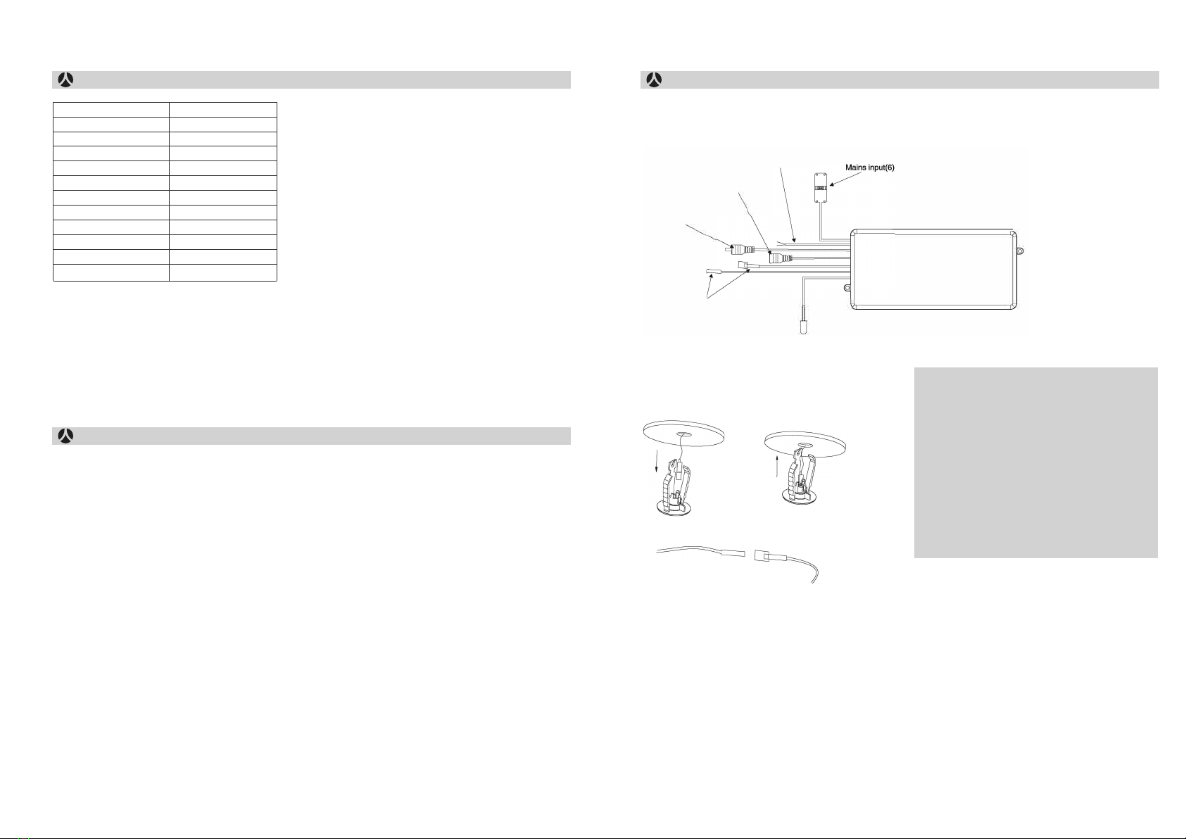
Connecting the Driver (1 &2)
The emergency pack is supplied pre-wired for
connection to the LED driver supplied with the
luminaire. Use the UN cable from the emergency
pack(1) as the input for the LED driver, and connect
the pre-wired connector from output of the driver
to input for emergency pack(2). Remove Safety
covers before installation.
Luminaire Input (3)
Connect the lead from emergency pack to the
connector on luminaire.
Indicator LED (4)
Drill a 18mm hole close to the installation location of
the luminaire. Feed the indicator cable through the
cut-out, insert into the housing then push both into
the ceiling until secure.
illuminate due to any stored battery charge.
Mains Input (6)
The emergency pack requires a permanent,
switched live and neutral. Earth is not required
as the
case is Class 2, but provision ha s been given for a loop through for earth. Connect to 4 way
connection block as per labelled.
Battery (5)
Push the battery connector together, ensuring
correct polarity. do not force plug.
NOTE - the luminare may illuminate due to any
stored battery charge.
Mains Input (6)
The emergency pack requires a permanent,
switched live and neutral. Earth is not required
as the


