Powermate PRTT196E User manual

Look inside for:
Page
Safety Definitions 1
Important Safety Information 2-4
Product Specifications 5
Parts & Features 5
Safety Decals 6
Assembly 7-9
Engine Preparation 10
Operation 11-15
Maintenance 16-19
Technical Service 19
Troubleshooting 20
Warranty 21-24
Français 26
Español 52
11/15/2012 Printed in China A202393
Operator’s Manual
Rear Tine
Rotary Tiller
IMPORTANT:
Thank you for purchasing this Powermate® Tiller.
This manual provides complete instructions for safely operating and maintaining your Tiller. Read and save these
instructions. Refer to this manual each time before using your Tiller.
Record the following for future reference:
Mfg. Date Code: __________________________
Date of Purchase: Attach a copy of your sales receipt.
Consumer Toll Free Number: 1-800-737-2112
Refer to the website for electronic manual and parts book.
www.powermateoutdoor.com
KEEP THIS MANUAL FOR FUTURE REFERENCE
MODEL NO.s PRTT196E
PRTT196
If you have a question or problem...
CALL TOLL FREE: 1-800-737-2112
WARNING CALIFORNIA PROPOSITION 65 WARNING
Engine exhaust, some of its constituents, and certain product components contain or emit chemicals known to the State
of California to cause cancer and birth defects or other reproductive harm.

1
Questions? Call Toll Free at 1-800-737-2112 Copyright © 2012 MAT Engine Technologies, LLC
Oil Fill Location
Do Not Overfill
Fuel ON/OFF Valve
Move Fuel Valve lever to the right to
operate the tiller.
Clutch Lever
Depressing the upper lever engages
the tines and drive wheels for the till-
ing operation. Depressing the lower
engages the tines and drive wheels for
reversing the tiller.
Choke Lever
Move Choke Lever to the left for cold
engine starting. Move Choke Lever to
the right once engine is started or for
warm engine starting.
Throttle Control
Move throttle lever to the left to
increase engine speed. Move throttle le-
ver to the right to decrease engine speed.
Indicates WARNING, DANGER, or CAUTION.
Wear eye protection complying withANSI
Z87.1 and hearing protection.
Read operator’s manual before operating this
machine. Failure to follow directions could
result in serious injury.
Disconnect spark plug wire when not in use
or before servicing, cleaning, or performing
maintenance on the unit.
Thrown objects. Remove all rocks, stones,
and foreign objects which could be thrown by
machine.
Engine exhaust contains carbon monoxide,
an odorless and deadly gas. NEVER run unit
indoors or in a poorly ventilated area.
Do not use if children or bystanders are present. Do NOT touch hot muffler or cylinder. These
parts are extremely hot from operation and
may remain hot for a short time after operation.
Rotating tines can cause serious injury.
Keep hands, feet, and clothing away.
To reduce risk of fire, clean spilled gas and
oil and keep unit free from debris. Gasoline is
extremely flammable. Allow machine to cool
before refueling.
Safety Definitions
• Save these instructions
Safety Warning Symbols
Control and Operating Symbols
Indicates an imminently hazardous situation which, if not avoided, will result in death or serious injury.
Indicates a potentially hazardous situation which, if not avoided, could result in death or serious injury.
Indicates a potentially hazardous situation which, if not avoided, may result in minor/moderate injury or
equipment/property damage.
DANGER
CAUTION
WARNING
The following symbols are used on the product and in this manual to alert the operator of potential safety hazards. Read them
carefully, and understand their meaning.
Safety Alert Symbols
The following symbols may be found on your tiller. Carefully read and understand their meaning.
Important Safety Information

2
Questions? Call Toll Free at 1-800-737-2112 Copyright © 2012 MAT Engine Technologies, LLC
RESPONSIBILITY OF OPERATOR
1. Carefully read and follow these safety instructions. Failure to do so can result in serious injury.
2.
Know your product. Read and understand this manual before use. Compare the illustrations to unit. Learn location
and function of all controls. Thoroughly understanding the unit before use will result in the best performance and safety.
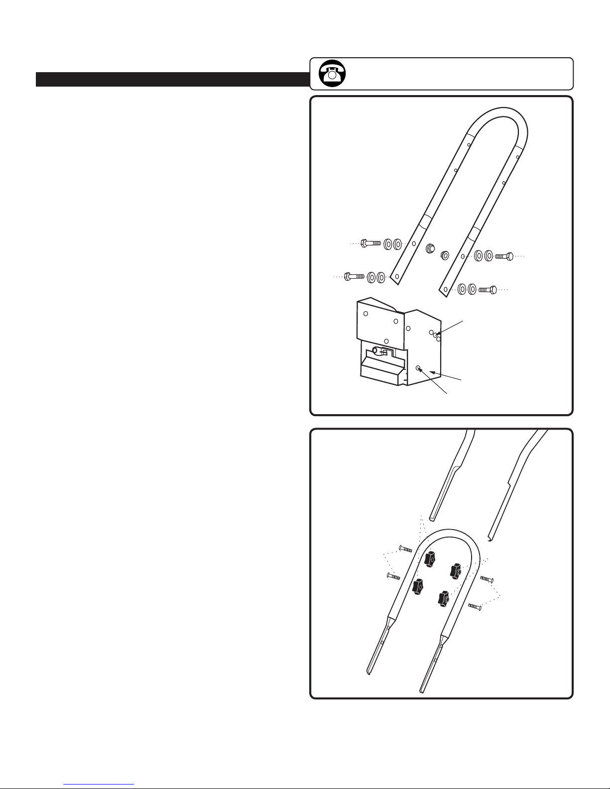
3. Follow all instructions when assembling the unit. If the unit was purchased in assembled condition, the operator must
check the unit carefully to make sure it was assembled according the instructions in the manual before use.
4. Regularly inspect the tiller. Make sure parts are not bent, damaged, or loose.
5. Use this equipment for its intended purpose only.
6. Operate the unit only with guards, shields, and other safety items in place and working correctly.
7. Service the unit only with authorized or approved replacement parts.
8. Complete all unit maintenance and adjustments according to the instructions in this manual.
WARNING
Look for this symbol to point out important safety precautions. It means: “ Attention! Become Alert! Your Safety Is Involved.”
WARNING
Engine Exhaust, some of its constituents, and certain vehicle components contain or emit chemicals known to the State
of California to cause cancer and birth defects or other reproductive harm.
WARNING
To prevent accidental starting when setting up, transporting, adjusting or making repairs, always disconnect spark plug
wire and put wire where it cannot contact the spark plug.
PREPARATION SAFETY
WARNING
• Read,understand,andfollowallinstructionsonthemachineandinthismanual.Bethoroughlyfamiliarwiththe
controls and the proper use of the tiller before starting. Know how to stop the engine quickly.
• Familiarizeyourselfwithallthesafetyandoperatingdecalsonthisequipment.
WARNING
• Thoroughlyinspecttheareawherethetilleristobeusedandremoveallforeignobjects.Yourequipmentcanpropel
small objects at high speed causing personal injury or property damage. Stay away from breakable objects, such as
house windows, auto glass, greenhouses, etc.
•Check that all nuts and bolts are tight and equipment is in good condition before each use.
OPERATION SAFETY
•Never allow children or young teenagers to operate the tiller.
WARNING
•Keep area of operation clear of all bystanders, particularly small children and pets.
•Only allow responsible individuals, who are familiar with the instructions, to operate the tiller.
WARNING
•Do not operate the tiller while under the influence of alcohol, drugs, or other medication which can cause drowsiness
or affect your ability to operate this machine safely.
•Do not use this machine if you are mentally or physically unable to operate the machine safely.
•Always wear ANSI compliant safety goggles or safety glasses with side shields when operating tiller to protect your
eyes from foreign objects, which can be thrown from the unit.
•Wear appropriate clothing such as a long sleeved shirt or jacket. Also wear long trousers or slacks. Do NOT wear
shorts. Do NOT wear loose clothing, which could get caught in this equipment.
Important Safety Information
• Save all instructions
Important Safety Information

3
Questions? Call Toll Free at 1-800-737-2112 Copyright © 2012 MAT Engine Technologies, LLC
Important Safety Information (Continued)
• Save all instructions
Important Safety Information
•Always wear work gloves and sturdy footwear such as leather work shoes or short boots. These will protect ankles
and shins from small sticks, splinters, and other flying debris, and improve traction.
•It is advisable to wear protective headgear to protect against being struck by small flying particles, or being struck by
low hanging branches, twigs, or other objects, which may be unnoticed by the operator.
WARNING
•Do not put hands or feet near or under rotating parts.
•Exercise extreme caution when operating on or crossing gravel drives, walks, or roads. Stay alert for hidden hazards or traffic.
WARNING
•Exercise caution to avoid slipping or falling. Always be sure of your footing; keep a firm hold on the handle and walk;
never run. Never operate the tiller at high transport speeds on slippery surfaces.
•Never operate the tiller without good visibility or light.
DANGER
•Do not run the engine indoors or inside a closed area. The exhaust fumes are dangerous, containing CARBON
MONOXIDE, an ODORLESS AND DEADLY GAS.
•Never leave the tiller unattended when the engine is running. Stop the engine and make sure all moving parts have
stopped. Remove the wire from the spark plug.
• Watch for holes, ruts, bumps, or other rough ground. Tall grass can hide obstacles.
• Alwayslookbehindanddownandusecautionwhenusingreverseorpullingthetillertowardsyou.
• Neverattempttostartthetillerunlessbothwheelsareinthelockedposition.Thisactsasabrakeforthetiller.
Always start the tiller on the level surface.
WARNING
• Disengage clutch lever and stop engine before leaving the tiller in operating position. Wait until the tines come to a
complete stop before removing debris or making any adjustments to the tiller.
CAUTION
• Do not attempt to till hard soil, till too deep or till at too fast a rate that can overload the tiller.
•If the tiller should start to vibrate abnormally, stop the engine, disconnect the spark plug wire and prevent it from
touching the spark plug. Check immediately for the cause. Vibration is generally a warning of trouble.
FUEL SAFETY
WARNING
• Gasolineisextremelyflammable,andgasolinevaporscanexplodeifignited.Handlewithcare.
• Useanapprovedcontainer.
• Checkfuelsupplybeforeeachuse,allowingspaceforexpansionastheheatoftheengineand/orsuncancausefuel
to expand.
• Fillfueltankoutdoorswithextremecare.Neverfillfueltankindoors.
• Neverremovegascaporaddfuelwiththeenginerunning.Allowenginetocoolbeforerefueling.
WARNING
• Donotsmokewhilerefueling.
• Afterrefueling,replacefueltankcapsecurelyandwipeupspilledfuel.
• Neverstorefuelortillerwithfuelinthetankinsideabuildingwherefumesmayreachanopenflame.
• Neverfillgasolinecontainersorthetillerfueltankinsideofavehicleorinatruckbed.Accidentalelectricalstatic
discharge can ignite fuel vapors which could result in serious injury or death.

4
Questions? Call Toll Free at 1-800-737-2112 Copyright © 2012 MAT Engine Technologies, LLC
Important Safety Information (Continued)
• Save all instructions
Important Safety Information
STORAGE SAFETY
•
Always refer to the operator’s manual instructions for important details if the tiller is to be stored for an extended period.
• Neverstorethetillerwithfuelinthefueltankinsideabuildingwhereignitionsourcesarepresentsuchaswater
heaters, space heaters, clothes dryers, etc.
• Toreducefirehazard,keeptillerfreeofgrass,leaves,orotherdebrisbuild-up.
•Allow the engine to cool before storing in any enclosure.
REPAIR, MAINTENANCE, AND ADJUSTMENT SAFETY
•After striking a foreign object, stop the engine. Remove the wire from the spark plug and keep the wire away from the
plug to prevent accidental starting. Thoroughly inspect the tiller for any damage. If damaged, have the equipment
repaired by a trained technician before restarting and operating.
WARNING
•Stop the engine before cleaning, repairing, or inspecting the unit. Make sure all moving parts have stopped. Let the
engine cool, disconnect the spark plug wire and move it away from the spark plug.
• Never attempt to make any adjustments while the engine is running except when specifically recommended by the
manufacturer.
•Keep the tiller in safe working condition. Check all fasteners at frequent intervals for proper tightness.
•When servicing or repairing the tiller, do not tip the machine over or up unless specifically instructed to do so in this
manual. Service and repair procedures can be done with the tiller in an upright position. Some procedures will be
easier if the machine is lifted on a raised platform or working surface.
•Use only original equipment or authorized replacement parts.
WARNING
•Never tamper with safety devices. Check their proper operation regularly.
•Do not change the engine governor setting or over-speed engine.
•Clean and replace safety and instruction decals as necessary.
•To guard against engine over-heating, always have engine debris filter mounted and clean.
CHILDREN SAFETY
WARNING
• Tragicaccidentscanoccuriftheoperatorisnotalerttothepresenceofchildren.Childrenareoftenattractedtothe
tiller and the tilling activity.
• Keepchildrenoutofthetillingareaandunderthewatchfulcareofaresponsibleadult.
• Neverassumethatchildrenwillremainwhereyoulastsawthem.
• Bealertandturntilleroffifchildrenenterthearea.
• Beforeandwhilemovingbackwards,lookbehindanddownforsmallchildren.
• Neverallowchildrentooperatethetiller.
•Use extra care when operating near blind corners, shrubs, trees, or other objects that may obstruct vision.

5
Questions? Call Toll Free at 1-800-737-2112 Copyright © 2012 MAT Engine Technologies, LLC
Product Specifications
• Save all instructions
Parts & Features
Unit Weight . . . . . . . . . . . . . . . . . . . . . . . . . . . . .154 lb (70 kg)
Tilling Width . . . . . . . . . . . . . . . . . . . . . . . . . . . 18 in (45.7 cm)
Tilling Depths . . . . . . . . . . . . . . . . . . . . . . . . . . . . . . . . .up to 6”
Tine Diameter. . . . . . . . . . . . . . . . . . . . . . . . . . .11 in (27.9 cm)
Gasoline Type .........Regular Unleaded/87 Octane (min.)
Gasoline Capacity . . . . . . . . . . . . . . . . . . . . .3.5 US qt. (3.3 L)
Engine Oil Type (API SG-SL) . . . . . . . . . . . . . . . . . . . . . . . . . . . .
10W-30 is recommended for all service temperatures.
See page (10) for additional information.
Engine Oil Capacity . . . . . . . . . . . . . . . . . . . 20 US oz (600 ml)
Transmission Oil Type . . . . . . . . . . . . . . . . . . . . SAE 90W-140
Transmission Oil Capacity . . . . . . . . . . . . . . 30 US oz (900 ml)
Spark Plug . . . . . . . . . . . . . . . . . . . . . . . . . . . . . . Torch F7RTC
1. Tines
2. Tine Shield
3. Wheels
4. Wheel Lock Pins
5. Muffler
6. Air Filter
7. Recoil Starter Handle
8. Spark Plug / Spark Plug Wire
9. Depth Regulator
10. Throttle Control
11. Fuel ON/OFF Valve
12. Choke Control
13. On/Off Switch
14. Fuel Tank Cap
15. Oil Dipstick
16. Forward Lever
17. Reverse Lever
18. Front Handle
Spark Plug Gap . . . . . . . . . . . . . . 0.028-0.031 in (0.7-0.8 mm)
Engine Type . . . . . . . . . . . . . . . . . . . . . . . . . . . . .OHV4-stroke
Engine Displacement . . . . . . . . . . . . . . . . . . . . . . . . . . . 196cc
Engine Speed (Full Throttle) . . . . . . . . . . . . . . . . . . . 3600 rpm
Engine Speed (Idle) . . . . . . . . . . . . . . . . . . . . . . . . . . 2100 rpm
Torque Rating........ 9.6 ft-lbs gross torque per SAE J1940
Bore Diam. x Stroke. . . . . . . . . . . . 2.7 x 2.13 in (68 x 54 mm)
Intake Valve Clearance . . . . 0.004 - 0.006 in (0.10 - 0.15 mm)
Exhaust Valve Clearance. . . 0.006 - 0.008 in (0.15 - 0.20 mm)
Angle of Ignition . . . . . . . . . . . . . . . . . . . . . . . . . . . .25 degrees
Tire Size .............. 13x5.00-6 Directional Tractor Tread
Tire Pressure . . . . . . . . . . . . . . . . . . . . . 20 psi min/30 psi max
Figure 1
9
1
2
10
3
4
5
6
7
8
11
13
15
14
16
17
12
18

6
Questions? Call Toll Free at 1-800-737-2112 Copyright © 2012 MAT Engine Technologies, LLC
Safety Decals
• Save all instructions
This tiller has been designed and manufactured to provide
you with the safety and reliability you would expect from an
industry leader in outdoor power equipment manufacturing.
Although reading this manual and the safety instructions it
contains will provide you with the necessary basic knowledge
to operated this equipment safely and effectively, we have
placed several safety labels on the tiller to remind you of this
important information while you are operating the unit.
These important safety labels are illustrated below, and are
shown here to help familiarize you with the location and
content to the safety messages you will see as you perform
normal tilling operations. Please review these labels now.
If you have any questions regarding their meaning or how
to comply with these instructions, reread the complete
safety instruction text on the preceding pages, or contact
your local dealer.
Should any of the safety labels become unreadable because
of being worn, faded, or otherwise damaged during the use
of your tiller, please contact your local authorized dealer to
order replacement labels.
The safety labels are easily applied, and will act as a constant
visual reminder to you and others who may use the equipment.
Following the safety instructions is necessary for safe, effective
operation of your tiller.
• Keep away from
rotating tines.
• Contact will result
in injury.
• Gasoline is flammable. Allow engine to cool at least 2 minutes
before refueling.
• Operation of this equipment may create sparks that can start
fires around dry vegetation. A spark arrestor may be required.
The operator should contact local fire agencies for laws or
regulations relating to fire prevention requirements.

7
Questions? Call Toll Free at 1-800-737-2112 Copyright © 2012 MAT Engine Technologies, LLC
Assembly
• Save all instructions
If you need assistance or find any parts missing, CALL
TOLL FREE: 1-800-737-2112.
Read and follow the assembly instructions. Do not discard any parts or materials until the unit is assembled.
References to the right or left side of the tiller are from the viewpoint of the operator’s position behind the tiller.
WARNING
Do not operate tiller if it is damaged or not completely and correctly assembled.
WARNING
Before doing any assembly or maintenance to the unit, remove the wire from the spark plug.
WARNING
Always wear ANSI compliant safety glasses with side shields while assembling the tiller.
The following components will be found in the carton.
Quantities shown in ( ).
1. (1) Tiller
2. (1)HandleAssembly
3. (1)FrontHandle
4. (2) Tine Assembly
5. (1) Tine Guard Assembly
6. (1) Drag Bar
7. (1) Tiller Operator’s Manual
8. (1) Engine Manual
9. (1) Bottle of Engine Oil
10. (1) Parts bag containing the following
a. Combination wrenches
b. (4)M8x25mmbolts,atwashers,locknutsfor
assembling front carry handle
1. Remove all parts and packaging components.
2. Use a utility knife to cut all 4 vertical edges and lay the
side panels flat around the tiller.
3. Remove any remaining packaging.
4. Remove the two bolts going thru the packing frame and
wheel axle holes.
5. Remove the two bolts located underneath the engine
that go thru the packing frame and thru the tiller base
frame.
6. With a helper, remove the tiller from the packing frame.
How to Remove Tiller from Carton
A
c.(2)M10x25mmangeheadbolts,lockwashersand
nuts for assembling lower handle
d. (4) M8x60 mm saddle bolts and washers for
assembling upper handle
e.(4)Handleknobsforassemblingupperhandle
f. (2) Wheel locking pins
g. (2) M10x50 mm bolts and lock nuts for assembling tines
h. (1) Pin
11. Stationary side shields with mounting hardware
12. (2) Wheel and tire assemblies
Wheel lock pin in tiller operating position
(wheel hub and axle holes)
FRONT
Figure 2

8
Questions? Call Toll Free at 1-800-737-2112 Copyright © 2012 MAT Engine Technologies, LLC
Assembly Instructions
B
Assembly (Continued)
• Save all instructions
If you need assistance or find any parts missing, CALL
TOLL FREE: 1-800-737-2112.
Pin
Depth Regulator Bracket
Depth Regulator Lever
Figure 3
The tiller comes fully assembled except for a few parts.
The following instructions will help you complete the tiller
assembly.
INSTALL THE WHEELS (See Figure 2)
1. Remove the locking pins from the axle.
2. The tiller wheels are directional. For best performance
install the wheels with the tire thread facing the direction
as shown.
3. Slide the wheel hub onto the wheel axle.
4. Align the wheel hub hole with the hole in the axle and
insert the locking pin.
5. Rotate the locking pin ring to lock the pin in position.
INSTALL THE TINES
1. Check the orientation of the tine blade. The sharp
cutting edge should be facing the direction of tine
rotation for your tiller.
2. Install the tine assemblies on each tine axle. Secure
with M10x50mm bolts and lock nuts. Do not over tighten
the tine bolt. This could damage the tine assembly and
cause difficulty in removing the tine assembly from the
tine axle.
INSTALL THE TINE SHIELD
1. Remove the 4 bolts installed in the tine shield brackets
above the transmission housing.
2. Place the tine shield on the bracket and secure with the
bolts removed in 1. above.
3. Install the tine shield side with the hardware provided.
INSTALL THE DEPTH REGULATOR (See Figure 3)
1. Remove the bolt and knob from the depth regulator lever.
2. Insert the depth regulator into the bottom of the depth
regulator bracket.
3. Insert the pin thru the bracket and lever.
4. Install the bolt and knob removed in 1. onto the depth
regulator lever.

9
Questions? Call Toll Free at 1-800-737-2112 Copyright © 2012 MAT Engine Technologies, LLC
Assembly (Continued)
• Save all instructions
If you need assistance or find any parts missing, CALL
TOLL FREE: 1-800-737-2112.
ATTACH LOWER HANDLE (See Figure 4)
1. Loosen the lower handle bolts.
2. Align the lower handle holes to the middle height
adjustment holes in the transmission cover and install
the M10 x 25 mm flange head bolts, lock washers and
nuts. Tighten all four bolts at this time.
ATTACH UPPER HANDLE (See Figure 5)
1. Slide the upper handle down over the lower handle and
align the holes.
2. Insert the saddle bolts into the holes as shown and secure
with the handle knobs.
3. Tighten the handle knobs securely.
ATTACH FRONT HANDLE (See Figure 1)
1. Slide the front handle onto the outside of the base frame
and align the holes.
2. InstallthefourM8x25mmbolts,atwashersandlocknuts
and tighten securely.
Saddle Bolts
Saddle Bolts Handle Knobs
Handle Knobs
Figure 5
Transmission Cover
Height
Adjustment
Holes
Lower Holes Figure 4

10
Questions? Call Toll Free at 1-800-737-2112 Copyright © 2012 MAT Engine Technologies, LLC
Engine Preparation (Continued)
• Save all instructions
Engine Oil
A
CAUTION
Engine shipped without oil. Failure to add oil will result in
serious engine damage.
A bottle of engine oil is included with your tiller. Refer to the
chart on the right for alternative oil types to use at different
temperatures. Always use a high quality detergent oil
classified“ForService,SG,SH,SJ”orhigher.Donotuse
special additives.
CAUTION
Always use recommended oil type. Using dirty oil or
incorrect oil type such as 2-stroke engine oil will shorten
engine life.
NOTE: Engine Oil Capacity is 20 oz. (0.6 L).
HOW TO CHECK OIL LEVEL AND FILL TO PROPER LEVEL
WARNING
Before checking oil, make sure engine is off, and spark
plug wire has been disconnected from spark plug.
1. Place the tiller on a level surface and make sure the
depth regulator lever is set so the main frame of the tiller
is level. (See Figure 6)
2. Removetheoilllcap/dipstickandwipecleanwith
cloth. (See Figure 6)
3. InsertdipstickintollspoutbutdoNOTscrewin.
Remove dipstick and check oil level.
4. When oil level is full, the oil will be at upper limit on dip
stick. If oil level is near or below the lower limit, oil must
be added. (See Figure 7)
5. Add oil slowly until the oil level reaches the upper limit
of the dipstick. Use a funnel or nozzle to reduce spillage.
CAUTION
Frequently check oil level while filling. DO NOT OVERFILL.
DO NOT UNDER FILL. Running engine at improper oil
level will seriously damage engine.
6. Replace and tighten dipstick.
7. Clean up any spilled oil.
NOTE: The transmission comes from the factory with the
proper amount and type of gear oil.
SAE
TEMP 100° F
40° C
-20
-20-30 -10
0
0
20
2010
40 60 80
30
Ambient Service Temperature
SAE 10W-30
SAE 30
Oil Fill Cap/Dipstick
Fuel Tank Cap
Oil Fill Cap/
Dipstick
Upper Limit
Lower Limit
Figure 6
Figure 7
Depth Regulator Lever

11
Questions? Call Toll Free at 1-800-737-2112 Copyright © 2012 MAT Engine Technologies, LLC
Operation
• Save all instructions
Pre-Start Inspection
A
1. Make sure all safety guards are in place and all nuts and
bolts are secure.
2. Check oil level in engine crankcase. See your engine
manualforprocedureandspecications.
3. Inspect air cleaner for cleanliness. See your engine
manual for procedure.
4. Check the fuel supply. Fill the fuel tank no closer than 1
inch from top of tank to provide space for expansion.
See your engine manual for fuel recommendations.
5. Be sure spark plug wire is attached and spark plug is
tightened securely.
6. Check position of wheels and wheel lockouts.
7. Check depth regulator lever position.
8. Examine underneath and around engine for signs of oil
or fuel leaks.
9. Inspect fuel hoses for tightness and fuel seepage.
10. Look for signs of engine damage.
11.Removeexcessivedebrisfrommuferareaandrecoil
starter.
IMPORTANT: Engine is shipped from factory without oil. YOU
MUST ADD ENGINE OIL BEFORE STARTING ENGINE.
CAUTION
Please do not start your tiller until you have read the
manual that came with your tiller, and the sections in this
manual tiller controls, adjustments and safety. If you have
read these, follow the steps below to start your tiller. Always
perform this pre-start checklist before starting the engine.
WARNING
Gasolineishighlyammableandmustbehandledwith
care.Neverllthetankwhentheengineishotorrunning.
Alwaysmoveoutdoorstolltank.
Wheels must always be locked in the tilling position when
engine is running. Do not operate the tiller with the wheel
lockouts unlocked. Always set the wheels in tilling position
before starting engine.
Always put depth regulator lever in the transport position
before starting engine. Tines should clear ground.
DANGER
Always keep hands and feet clear of rotating machine parts.
Start-Up
B
The controls required to start and run the tiller are located on the engine and are marked with the icon for choke, slow
and fast for the throttle, and on/off fuel valve. A more detailed description of engine operation and all related precautions
and procedures can be found in the engine manufacturer’s manual that accompanies each tiller.
COLD STARTS
1. Turn the Engine Switch to the “on” position.
2. Open the Fuel Valve.
3. Move choke lever to left for full choke position.
4. Move throttle lever to “start” or “fast” position.
5. Pull starting rope out slowly one time and allow to return
normally.
6. Pull starting rope out rapidly, and allow rope to return
normally.
7. When engine starts, gradually move choke lever to “no
choke” position and increase throttle speed.
RESTARTING A WARM ENGINE
Restarting an engine that is already warm from previous
running does not normally require use of the choke.
1. Move throttle lever to “start” position or “fast” position.
2. Pull starting rope out rapidly until engine starts. Allow
rope to return normally. Repeat until engine starts.
3. Adjust throttle speed to “fast” for best tiller performance.

12
Questions? Call Toll Free at 1-800-737-2112 Copyright © 2012 MAT Engine Technologies, LLC
Operation (Continued)
• Save all instructions
Idle Speed
C
Usethe˝slow˝positiononthethrottlelevertoreducestress
on the engine when tilling is not being performed. Lowering
theenginespeedto˝idle˝willhelpextendthelifeofthe
engine, as well as conserve fuel and reduce the noise level of
the equipment.
Operating Speed
D
Fornormaltilling,setthethrottleleverto˝fast˝.
Shutting Down
E
To stop the engine at any time, turn engine ON/OFF switch to
the off position. To stop wheels and tines at any time, release
drive safety control levers to neutral position.
Tilling
F
1. Adjust the depth regulator lever to desired tilling depth.
WARNING
NOTE: Raise drag bar up one hole at a time, testing tiller
operation after each raise. Raising drag bar too high can result
in loss of control of tiller!
2. Move the throttle control to fast.
3. Place the tiller in forward by pushing down on the drive
safety control lever (FORWARD)--this will engage the wheels
and tines.
NOTE: You can slow the tiller’s forward advance at any time by
putting slight downward pressure on the handlebars. You can
stop the tiller by releasing the drive safety control levers to the
neutral position.
CAUTION
Always press the forward or reverse drive levers down
completely onto the handle bar. Failure to do so may result in
excessive drive belt wear and premature drive belt failure.
WARNING
Temperatureofmuferandnearbyareasmayexceed150˚F.
Avoid these areas. Do not move choke control to stop engine,
backreorenginedamagemayoccur.Tostopwheelsandtines
at any time, release drive safety control levers to neutral position.
Always release drive safety control levers to neutral position AND
STOPTHEENGINEbeforeadjustingthedepthoftheregulator
lever.
DANGER
Engine and surrounding parts become extremely hot during nor-
mal use and will cause serious burn injuries if touched before the
engine has cooled. Allow engine to cool completely before touch-
ing these hot surfaces.
IMPORTANT: Practice operating the controls and tiller with tines out
of ground before beginning to till. It is important that you know how
to use the tiller properly, keep control at all times, stop the tines
and wheels from turning, and stop the engine if necessary. If you
do not know how to do these things, read the controls, adjust-
ments and safety sections before proceeding.

13
Questions? Call Toll Free at 1-800-737-2112 Copyright © 2012 MAT Engine Technologies, LLC
Drive Safety Control Levers
G
FORWARD LEVER (See Figure 9)
Engages wheels and tines into forward. Pushing down
the drive safety control lever (FORWARD) toward the
handlebar engages the wheels and tines. Releasing the
lever stops the wheels and tines and brings the tiller to a
complete stop.
Operation (Continued)
• Save all instructions
CAUTION
Donotoperateboth˝FORWARD˝and˝REVERSE˝drivesafetycontrolleversatthesametime.
This information is provided here only to introduce the controls. Do not start the engine at this time. Starting and operating instructions
are given on page 11. Please read this section and all operating and safety instructions before starting your tiller.
• Asasafetyprecaution,thedrivesafetycontrolleverswillnotlockintheforwardorreverseposition.
WARNING
Donotxtheforwardorreversedriveleversinthedrivepositionbyanyothermeansthanmanuallyusingyourrighthand.Donottieor
otherwise secure the levers in the drive position.
• Tostopthewheelsandtinesatanytimereleasethedrivesafetycontrollevers.
REVERSE LEVER (See Figure 10)
Engages wheels and tines into reverse.
Pulling the drive safety control lever (REVERSE) toward
the handlebar reverses tiller.
Releasing the lever stops the wheels and tines.
Forward Lever
Engaged
Figure 9
Reverse Lever
Engaged
Reverse Lever
Figure 10

14
Questions? Call Toll Free at 1-800-737-2112 Copyright © 2012 MAT Engine Technologies, LLC
Adjustments
H
Operation (Continued)
• Save all instructions
WHEEL LOCK PINS (See Figures 2 and 11)
Place wheels in tilling position.
1. Remove lock pin. Align hole in axle with hole in wheel hub.
2. Insert lock pin through holes, fold lock pin ring to secure
pin to axle.
3. Firmly lock wheel and axle together before tilling.
4. Repeat for other wheel.
WARNING
Always have both wheel lock pins in or out. Do not operate
tiller with only one wheel locked.
To place wheels in free-wheel position.
1. Remove lock pin. Slide wheel inward toward machine.
2. Insert pin in axle only, fold lock pin ring to secure pin to axle.
3. Wheel should turn freely on axle.
HANDLEBAR HEIGHT ADJUSTMENT (See Figure 4)
Adjust handlebar height.
The ideal height of the handlebar varies with operator
height and the depth of tilling. To adjust handlebar height:
1. Unscrew nuts and remove top bolts on each side.
2. Loosen the lower bolts. Do not remove.
3. Align handlebar to desired holes on the lower handlebar
mount.
4. Install bolts and nuts. Retighten all four bolts securely.
DRAG BAR (See Figure 3)
Tilling depth is controlled by the height of the
drag bar. To adjust tilling depth:
1. Remove pin.
2. Raise the drag bar to position tines at chosen tilling depth.
3. Align hole in drag bar with hole in depth regulator
bracket and replace pin.
Drag Bar Down = Shallower tilling.
Place the pin in the top hole of the drag bar for shallowest tilling.
Drag Bar Up = Deeper tilling.
Place the pin in the bottom hole of the drag bar for deepest tilling.
WARNING
Engine should be off before ad-
justing any controls.
Extreme caution should be used
when operating tiller in the reverse
direction.
Wheel lock pin in free-wheel position
(axle holes only)
FRONT
Figure 11
WARNING
Do not adjust tilling depth unless drive safety control levers are
released to neutral position.
Always set the drag bar in the transport position before
starting engine, that is, place the detent pin in the highest
hole of the drag bar.

15
Questions? Call Toll Free at 1-800-737-2112 Copyright © 2012 MAT Engine Technologies, LLC
Operation (Continued)
• Save all instructions
Adjustments (Cont.)
I
BELT TENSION ADJUSTMENT (See Figure 12)
Proper belt tension is critical to good performance. After
1/2 hour of operation, all cables may have to be adjusted
due to initial stretch. Thereafter, check tension after every 2
hours of operation.
TO INCREASE BELT TENSION
1. Loosen upper jam nut. Turn nut up cable in 1/8” increments.
2. Tighten lower jam nut.
3. Check adjustment. With lever engaged, spring length
should be 0.8 in (20 mm).
TO DECREASE BELT TENSION
1. Loosen lower jam nut. Turn nut down cable in 1/8” increments.
2. Tighten upper jam nut.
3. Check adjustment.
This procedure can be repeated until conduit adjustment
bolts are fully adjusted. If no more adjustment can be
made, belt may have to be replaced.
Forward Cable
Reverse Cable Upper Jam Nut
Lower Jam Nut
Spring
Figure 12
Tilling Tips
J
The key to successful tilling is to begin with a shallow cut
on the first pass, and then work an inch or two deeper on
each successive pass.
• Tillingdepthwillvarywithgroundconditions.
• Whenbeginningtotillinunbrokengroundorin
extremely hard soil, set the pin in the highest hole of the
drag bar (follow instructions under Tilling
section). This will allow for shallow tilling. With the drag
stake in this position, make several light passes over the
area to be tilled. Reset for deeper depths with
successive passes.
• Iftillerjumpsorskidsuncontrollably,lowerthedrag
stake by placing the pin in a higher hole. This will allow
forshallowertilling.Holdfirmlytothehandlebarsto
control sudden lurches.
• Ifweeds,tallgrasses,vines,orothermaterialsclogor
jam the tines, reverse the tiller to unwind vegetation.
Cultivating Tips
K
If you plan to use your tiller for cultivating:
• Plantrowson20"-22"centersforeaseofturning.
• Setthedepthregulatorleverwiththedetentpininoneofthehigherholes.Thiswillallowforshallowcultivation
necessary to turn over weeds, and break up and aerate the soil.
WARNING
Immediately release the drive control levers if the tines jam
or you strike a foreign object. With drive control levers in
neutral position, stop the engine. Disengage the spark plug
wire. When tines have stopped, remove foreign objects and
check for damage.
WARNING
Extreme caution must be taken in selecting tilling depth. If
you attempt to till too deeply for soil conditions, that is, with
the depth regulator lever in too high a position, loss of control
could result.
If removing material from the tines by hand, stop engine and
removesparkplugwirerst.

16
Questions? Call Toll Free at 1-800-737-2112 Copyright © 2012 MAT Engine Technologies, LLC
Maintenance
• Save all instructions
Maintenance Schedule
A
WARNING
Before performing any maintenance, turn engine off and remove the wire from the spark plug to prevent accidental starting
and serious injury.
IMPORTANT: The warranty on this tiller does not cover items that have been subjected to operator abuse or negligence. To
receive full value from the warranty, the operator must maintain the tiller as instructed in this manual, and only use genuine
replacement parts. The following table lists required periodic maintenance.
PERIODIC MAINTENANCE SCHEDULE TABLE
CAUTION IMPORTANT NOTES about Maintenance schedule
1. Re-check tightness of all fasteners after first 2 hours of initial use
2. Change engine oil after first 5-8 hours of initial use
3. Change oil every 25 hours if operating under heavy load or in high temperatures
4. Clean air filter every 10 hours if operating under dusty conditions.
WARNING
Use only GENUINE replacement parts. Other parts may damage the unit or result in injury.
Service Records-
Fill in dates as you complete regular
service
Before
Each Use
After Every
10 Hours
of Use
After Every
25 Hours
of
Use
After Every
50 Hours of
Use
After Every
100 Hour
of Use
Before
Each
Season
Before
Storage
See
Note
Below
Check Engine Oil Level,
Fill to Proper Level √ √
Clean Debris From Unit √ √ √
Lubricate All Pivot Points √√ √
Check Fasteners for Tightness √ √
1
Check Drive Belts
Replace if Necessary √ √
Check Tines for Wear or Damage
Replace if Necessary √ √
Check Fuel Line
Replace if Necessary √ √
Lubricate Wheel Axles √ √ √
Check Spark Plug
Replace if Necessary √ √
Change Engine Oil √ √ √
2,3
Clean Air Filter
Replace if Necessary √ √
4
Replace Spark Plug √
Clean Combustion Deposits from
Cylinder, Piston, and Valves √
Check Transmission Oil √ √

17
Questions? Call Toll Free at 1-800-737-2112 Copyright © 2012 MAT Engine Technologies, LLC
Maintenance (Continued)
• Save all instructions
Servicing the Tiller
B
WARNING
To prevent accidental starting:
Engine must be turned off
and cool, and spark plug
wire must be removed and
secured from spark plug
before checking and adjust-
ing engine or equipment.
CHANGE FORWARD/REVERSE BELTS
(See Figure 12 and 13)
1. Turn off engine. Engine must cool completely before
proceeding.
2. Remove spark plug wire and secure away from spark plug.
3. Reduce the belt tension by loosening the forward and
reverse cable lower jam nut.
4. Remove the upper and lower belt guards.
5. To remove the reverse drive belt:
a. Remove the reverse belt idler.
b. Slide the belt free of the reverse belt guides and
engine pulley.
c. Pull belt down and away from the transmission pulley.
6. To remove the forward drive belt:
a. Remove the two forward belt guide studs and
forward belt idler assembly.
b. Slide the belt free of the engine pulley.
c. Pull the belt down and away from the transmission
pulley.
7. To install the forward drive belt:
a. Insert the belt from underneath the unit and up
around the rearward portion on the engine pulley.
b. Place the lower loop of the belt around the rearward
portion of the transmission pulley.
c. Replace the two forward belt guide studs and
forward belt idler assembly.
8. To install the reverse drive belt;
a. Insert the belt from underneath the unit and up
around the reverse belt idler.
b. Place the lower loop of the belt around the forward
portion of the transmission pulley.
c. Replace the reverse belt idler into the reverse belt
idler bracket. The belt should not go around the
engine pulley. Be sure the belt is inside of the
reverse belt guide studs.
9. Tighten the forward and reverse lower jam nut.
10. Check the belt tension. The belts should be loose with
the drive levers disengaged.
ENGINE PULLEY
Forward Belt
Reverse Belt
TRANSMISSION
PULLEY
Reverse Belt Idler
Forward Belt Idler
Figure 13
wire
tab
The following information will help you make the necessary checks and perform the procedures required to follow the
normal care recommendations made for your tiller unit. If you prefer, your local authorized dealer can make these checks
and perform the required procedures for you.
11. Replace the upper and lower belt guards.
12. Re-attach the spark plug wire to the spark plug.
13. Follow Operating Instructions – start the engine and
operate the forward drive lever to check for proper
cable adjustment and belt tension. See the Belt
Tension Adjustment section if cable adjustment is
required.
14. Start the engine and operate the reverse drive lever to
check for proper cable adjustment and belt tension.
See the Belt Tension Adjustment section if cable
adjustment is required.
WARNING
The tines or wheels should not rotate with the engine run-
ning, the depth regulator set at transport height (lowest
height) and the drive lever not engaged.

18
Questions? Call Toll Free at 1-800-737-2112 Copyright © 2012 MAT Engine Technologies, LLC
Maintenance (Continued)
• Save all instructions
Engine Maintenance
C
ENGINE MAINTENANCE
Refer to the engine manual included in your parts packet
for information on engine maintenance. Your engine
manual provides detailed information and a maintenance
schedule for performing the following tasks:
1. Check oil level before each use or after every 8 hours
of operation.
2. Change oil after first 5-8 hours of operation. Change oil
while engine is warm. Refill with new oil of recommended
grade.
3. Check spark plug yearly or every 100 hours of operation.
4. Service air cleaner.
5. Keep engine and parts clean.
6. Check engine and equipment often for loose nuts and
bolts, keep these items tightened.
CHECK OR FILL ENGINE CRANKCASE
IMPORTANT: Engine is shipped from factory without oil. You
must add engine oil before starting engine.
1. Add oil according to engine manual. Do not overfill.
Use a clean, high quality detergent oil. Do not mix oil
with gasoline. Oil level must be full. Check the oil level
by removing oil fill plug.
2. Always check oil level before starting engine. Refer to
engine manual for capacity and type of oil to use.
CHECK TILLER TRANSMISSION OIL
IMPORTANT: Tiller transmission is shipped from factory with
the proper amount of oil. When replacing oil, the tiller
transmission holds 27-30 ounces. Do not overfill.
Check the oil level annually. To check the oil level:
1. Move tiller to level ground.
2. Remove oil level dipstick located between the
handlebar mounts on the engine mount. If the oil
level is near or below the lower limit, fill the oil to
recommended level.
3. Replace oil level dipstick in the filler hole.
4. Note that the drive wheel transmission and rear tine
transmission are one common reservoir. When you add
to the front transmission, you must wait a short period
of time for the oil to flow rearward and equalize in
both front and rear. The dipstick will read correctly on
level ground for both gear units.
CHECK TIRE PRESSURE
Recommended tire pressure is 30 PSI. If tires do not have
equal pressure, tiller will pull to one side. Low tire pressure
may result in damage to tire tube.
LUBRICATION
Proper lubrication of moving mechanical parts is critical for
proper care and maintenance. Oil the moving parts shown
at 10 hour intervals using a 30 weight oil.
CLEAN TINE AXLE SHAFT
1. Turn off engine. Engine must be cool.
2. Remove spark plug wire and secure from spark plug.
3. Tip the tiller forward. Block the tiller in position so that it
rests on the engine mount and the tines are exposed.
4. Remove all vegetation, string, wire, and other material
that may have accumulated on the axle between the
inside set of tines and the seal cover on the
transmission housing.
5. Tip the tiller back to a level position.
6. Replace spark plug wire.
Gear Case Dipstick
Transmission
Cover Plate
Figure 14

19
Questions? Call Toll Free at 1-800-737-2112 Copyright © 2012 MAT Engine Technologies, LLC
How to Prepare for Storage
D
WARNING
Never store the tiller indoors with fuel in the fuel tank. Never store in an enclosed, poorly ventilated area where fumes
couldreachanopename,asparkorapilotlightasonafurnace,waterheaterorclothesdryer.Allowenginetocool
before storing unit.
WARNING
Donotremovegasolinewhileinsideabuilding,nearare,orwhileyousmoke.Gasolinefumescancauseanexplosion
orare.
NOTE: A yearly checkup or tune-up at an authorized service center will make sure that the tiller will provide maximum per-
formance for the next season.
When the tiller is put in storage for thirty days or more, the following steps should be followed to make sure the tiller is in good
condition the next season.
1. Let the engine run until it is out of gasoline.
2. Change the oil by following instructionsunder“HowtoChangetheOil.”
3. Remove the spark plug from the cylinder. Pour one ounce of oil into the cylinder. Slowly pull the recoil-start handle so
that the oil will protect the cylinder. Install a new spark plug in the cylinder. Pull starter handle slowly a few times to
distribute oil. Pull recoil slowly until resistance is felt. This will close the cylinder valves.
WARNING
DO NOT attach spark plug wire to spark plug when storing unit.
4. Clean tiller. Remove all dirt, leaves, debris, grease, etc. from the tiller - including cylinder cooling fans, recoil starter
coverholes,underfueltank,andundermufer.
5.Checkthetillerforwornordamagedparts.Havedamagedpartsreplacedifnecessary.
6. Tighten any loose hardware.
7. Apply lubrication as directed in Maintenance section.
8. Put the unit in a building that has good ventilation.
9. Cover the tiller with a breathing material.
Maintenance (Continued)
• Save all instructions
You may have further questions about assembling, operating, or maintaining this TILLER. If so, you can contact our
Technical Service Department at 1-800-737-2112 (English only).
You may also write to:
METL Corporate Office - CORRESPONDENCE ONLY
ATTN: Technical Service – METL
213 Industrial Drive
Jackson, TN 38301
Technical Service
When contacting the Technical Service Department, have ready:
• YourName
• YourAddress
• YourPhoneNumber
• ModelNumberofProduct
• DateofPurchase(includecopyofreceiptforwrittenrequests)
• DateCodeonProduct
If you need assistance or have any questions, CALL
TOLL FREE: 1-800-737-2112.
This manual suits for next models
1
Table of contents
Languages:
Other Powermate Lawn And Garden Equipment manuals
Popular Lawn And Garden Equipment manuals by other brands

Zero Moustique
Zero Moustique ECO-04 instruction manual

Urban Cultivator
Urban Cultivator Residential user manual

Lucky Duck
Lucky Duck Super Swimmer HD 10516-0 quick start guide

Pioneer Athletics
Pioneer Athletics BRITE STRIPER 1600PS Instruction manual and parts listing and parts listing

CobraCo
CobraCo UNCB-12-B Assembly instructions

Terra
Terra TerraCity TRI SET Assembly instructions