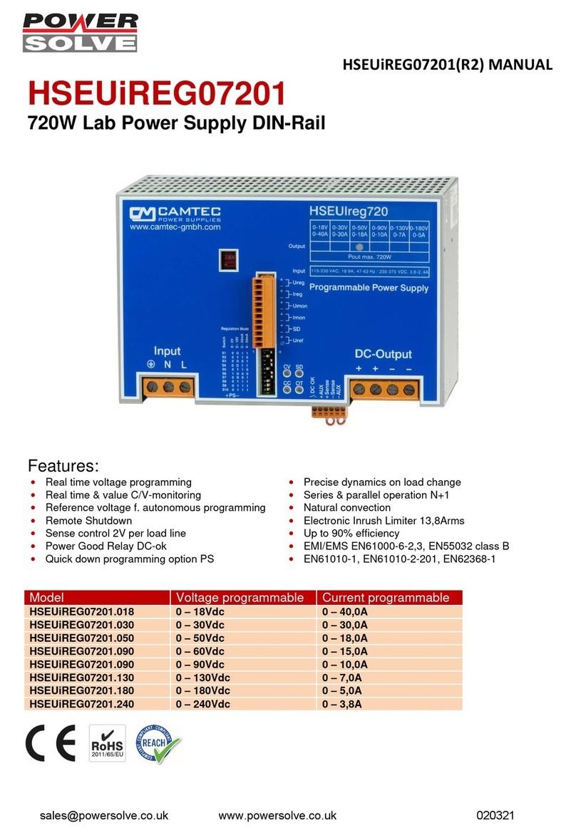
Powersolve CPS-EC1000 User manual

CPS-EC1000(R2) MANUAL
CPS-EC1000 1008W Precision DC Rectifier
DIN-Rail Battery Charger, C/V Adjustable Industrial Power
Specification:
•Real time output current monitoring
•Precision potentiometer f. voltage & current
•Power Good Relay AC & DC-ok
•C/V curve down to 0V, no foldback
•Sense control 1V per load line
•Electronic inrush current limiter 13.8Apeak
•Inhibit function (Interlock)
•External shutdown
•Efficiency up to 92%
•Precise dynamic response to load change
•Designed for long life under full stress
•Strong input filters
•Hold up time >30ms
•Soft start & auto-recovery
•High reliability, shock & vibration proof
•EMC meets CE norm class B
•Overload and short circuit protection
•Large terminals 4x AWG22 – AWG6 (0,5 – 16mm²)
Models
Voltage
Voltage setting
Current setting
CPS
-
EC100
0.024
24Vdc
24
–
30Vdc
21
–
44,1
A
CPS
-
EC100
0.036
36Vdc
36
–
45Vdc
14
–
29,4
A
CPS
-
EC100
0.048
48Vdc
48
–
58Vdc
10,5
–
22
A
CPS
-
EC100
0.060
60Vdc
60
–
75Vdc
8,4
–
17,6
A
CPS
-
EC100
0.072
72Vdc
72
–
90Vdc
7
,0
–
14,6
A
CPS
-
EC100
0.110
110Vdc
110
–
137
,5
Vdc
4,6
–
9,6
A
CPS
-
EC100
0.150
150Vdc
132
–
180Vdc
3,4
–
7
A
CPS
-
EC100
0.220
220Vdc
220
–
264Vdc
2,3
–
4,8
A
CPS
-
EC100
0.300
300Vdc
264
–
360Vdc
1,7
–
3,5
A
www.powersolve.co.uk
020321

CPS-EC1000(R2) MANUAL
Technical Concept
The Camtec CPS-EC series is a high precision switch mode power supply for an upscale demand. The unit is
C/V adjustable. It is engineered and manufactured by CAMTEC in Germany. The designed meets challenging
applications like railway, complex drives, battery charging for DC-UPS, test-stands, machine-building and
professional LED lighting. The power supply provides a low ripple-noise, a precise load-regulation and high
efficiency up to 94%. High-end long-life capacitors guarantee an extended hold-up-time and an extraordinary
lifetime of the power supply. The circuit design starts complex loads easily. The internal control circuit manages
illegal operating conditions to prevent your system from damages. The CPS-EC series features active high input
transients with suppressor diodes, X2-capacitors and varistors. All inputs, outputs and feature connections are
galvanic isolated. The design rules set value on extended interference immunity and safety. The unit is designed
in accordance with the EN60950-1, EN62368-1, EN61010-1, EN61010-2-201 and the EMC-compatibility with
EN55032.
Features
Design Conception
The CPS-EC power supply series realizes very high-power efficiency in a
space-saving housing. Latest generation electrical devices relate to the
high reliability of all CAMTEC products. The CAMTEC philosophy is, to
employ 125°C low ESR ultra long-life capacitors where expedient to
achieve a superior lifetime of the product. The CPS-EC power supply is
made for high reliable and demanding industrial applications, railway,
unbreakable power supply charger (DC-UPS), professional high-power
lighting (floodlight, production hall) and for telecom & demanding IT
applications.
Voltage Setting Potentiometer
The output voltage limit can be adjusted with a 15 turns high precision
potentiometer. The listed values are guaranteed by the factory. The
tolerance of the upper margin is -0/+5%. The tolerance of the lower margin
is -5%/+0%. The output voltages cover the typical cell voltage range of
standard lead acid batteries.
Current Setting Potentiometer
The output current limit can be adjusted with a 15 turns high precision
potentiometer. The listed values are guaranteed by the factory. The
tolerance of the upper margin is -0/+5%. The tolerance of the lower margin
is -5%/+0%.
Output Current Monitoring
The CPS-EC power supply features a 0-5Vdc signal output. It is a real-
time linear signal and indicates the current consumption of the load. The
measuring point is directly at the output connection of the device.
Sensing
The device has a sense operation mode to compensate a voltage drop at
the load line.
Inhibit contact (Interlock)
The inhibit inputs can be connected to a safety contact or a safety relay.
When the contact is open the power supply will remain in a completely
locked shut down mode. The unit powers up as soon as the contact is
closed.
External Shutdown feature
All CPS-EC units are featured with a shutdown (open collector).
DC-ok Power Good Relay
The PG Relay connection indicates over temperature, low DC-voltage at
the output, low AC supply voltage at the input, the inhibit and the shutdown
mode.
Galvanic Isolation
The power supply is galvanic isolated between the input and the output. All
features like Shut Down, Inhibit, Power Good Relay, Sensing and the Current
Monitoring are connected to the DC power outputs.
Thermal shutdown
The CPS-EC series is featured with a thermal overload shut down and auto
recovery behaviour.
Over Voltage Protection
Ticker mode and auto recovery
Short Circuit Protection
A continuous short circuit does not cause damage to the power supply. The CPS-
EC delivers constant current and 0 output voltage.
It recovers automatically after the short circuit is released.
Open Circuit Protection
The CPS-EC series is continuously open circuit protected. The device delivers a
stable output voltage and no current. If a load is immediately connected to the
device, the power supply stabilizes within 1ms. It does not overshoot the output
voltage.
Power Up Ramp
The devices have a soft start ramp when powering up. The device does not either
overshoot the voltage nor does the output flutter – independent if a load is
connected or not.
Inrush Limiter
The power supply provides an electronic inrush current limiter that works absolute
accurately with a low inrush of only 9,8A RMS value. The limiter works
independent from the ambient temperature and its tolerance is only ±10%.
Current Voltage Chart, CV & CC mode
The CPS-EC series provides a perfect current voltage chart. It has no fold back or
other abnormalities. The output voltage can drop down to zero volts when the
power supply is overloaded. The unit delivers a stable and constant current to the
outputs. The device can be used either in the CV or in the CC mode (auto switch).
www.powersolve.co.uk
020321

CPS-EC1000(R2) MANUAL
Technical Data Table
AC Input Range
90
–
132Vac / 184
–
26
4
Vac , 47
–
63Hz
(115/230Vac input selector, factory setting is 230Vac)
DC Input Range
250Vdc
–
375Vdc (input selector set to 230Vac)
AC Input Rat
ed
115Vac<1
7,2
A 230Vac<9,
8
A
DC Input Rat
ed
250Vdc<5,0A 375Vdc<3,3A (input selector set to 230Vac rated)
Rated DC
Voltage
24Vdc
36Vdc
48Vdc
60Vdc
72Vdc
110Vdc
150Vdc
220Vdc
300Vdc
Rated DC Current
42A
28A
21A
16,7A
13,9A
9,1A
6,7A
4,55A
3,33A
DC Voltage Setting Range 24 –
30Vdc
36 –
45Vdc
48 –
58Vdc
60 –
75Vdc
72 –
90Vdc
110 –
137,5Vdc
132 –
180Vdc
220 –
264Vdc
264 –
360Vdc
DC Current Setting Range 21 –
44,1A
14 –
29,4A
10,5 –
22A
8,0 –
17,6A
7,0 –
14,6A
4,6 –
9,6A
3,4 –
7,0A
2,3 –
4,8A
1,7 –
3,5A
Over
V
oltage Protection
34Vdc
50Vdc
67Vdc
84Vdc
100Vdc
154Vdc
210Vdc
310Vdc
420Vdc
Over
Current Protection
44,1A
29,4A
22A
17,6A
14,6A
9,6A
7,0A
4,8A
3,5A
Ripple
Noise
230Vac 20MHz
40mV
40mV
100mV
150mV
200mV
300mV
400mV
400mV
400mV
P
ower Rated
1008W
, 90
-
132Vac, 184
-
264Vac
Potentiometer C/V
Setting
15 turn
s
high precision,
protective
forced
isolation to the inputs and the output
3000Vac
Operation Failure Relay
Yes, break contact
, prot
ective
forced
isolation to the inputs and the output
3000Vac
Sense Function
Compensation 1V per
load
line
Remote
Shutdown
Yes,
protective
forced
isolation to the inputs and the output
3000Vac
Inhibit Function (Interlock)
Yes,
protective
forced
isolation to the inputs and the output
3000Vac
Derating
+60°C...+70°C 2.5%/°C
Accura
cy
< ± 1.5% interface
Load
Regulation
< ± 0.05% 0
-
100%
Start up from Shutdown
Typ. 320ms
Start up from Inhibit
Typ. 320ms
Response
to
Load Change
<1ms 10
-
100%, 100
-
10%
Base Load
None
required
(open circuit proof)
Efficiency 230Vac
Up to 92% at
90%
load
Short Circuit
Protection
Continuous
Open Circuit Proof
C
ontinuous
Temperature Control
Yes, thermal shutdown with auto recovery (+70°C, metering distance 10mm)
Hold Up Time
>3
0ms 230Vac
Inrush Current
<9,8Aeff < 13.8Apeak (230Vac) active inrush current limiter
Soft
S
tart
100ms typical
Cooling
Controlled Fan from manufacturer EBM Papst (Germany)
Ambient Operating Temp.
-
25°C…+70°C
Ambient Storage Temp.
-
40°C…+85°C
Environment
Humidity 95% non
-
condensing @ 25°C, climate class. 3k3, pollution rate II
ROHS
2011/65/EU, (EU)2015/863
REACH
EG No. 1907/2006
EMI
EN55032 conducted class B, radiated class A, EN61000
-
6
-
3
EMS
EN61000
-
6
-
2
Safety
EN61010
-
1, EN61010
-
2
-
201, EN62368
-
1 (not 300Vdc model),
EN60950
-
1,
EN60204
-
1
Protection Class 1
PE
connection required
Isolation Paths
> 8mm creepage distance & clearance paths
Input to O
utput
Isolation
3000Vac
Input to Case Isolation
2500Vac
Output to Case
Isolation
500Vdc , models
≥
48
Vdc
2
5
00V
d
c
Meantime By Failure (MTBF)
389
000h
(IEC61709)
Meantime To Failure (MTTF)
14
3
034
h (IEC61709)
Dimensions (HxWxD)
156
x200x11
4.
5
mm
Weight
34
00g
AC
Terminals
Input Screw Terminal
3x
AWG2
2
–
AWG6
/
0,5
–
16
mm²
(L,N,PE)
DC
Terminals
Output Screw Terminal
4x
AWG2
2
–
AWG6 / 0,5
–
16mm²
(+ + /
-
-
)
www.powersolve.co.uk
020321

CPS-EC1000(R2) MANUAL
Manual and Technical Details
1) Active Transient Filter 2) Rectifier 3) Inrush Current Limiter 4) Load Capacitor 5) Power Transformer 6) Storage Choke
LED: CV = constant voltage operation CC = constant current operation SD/INH = shutdown / inhibit OT = temperature failure >70°C
Technical Data Table
-
Analogue Interface
& Voltage Current Control
Feature
Technology
Details and Connections
Section
Isolation
Potentiometer Voltage
15 turns
High precision
U adj
3000Vac to input & output
Potentiometer Current
15 turns
High precision
I adj
3000Vac to input & output
Monitoring Current
0...5
Vdc/5mA
AWG22
–
AWG6 / 0,25
–
2,5mm²
I mon
3000Vac
to input
Shutdown
Open Collector
AWG22
–
AWG6 / 0,25
–
2,5mm²
SD
3000Vac
to input & output
Inhibit (Interlock)
Passive
AWG22
–
AWG6 / 0,25
–
2,5mm²
Inhibit
3000Vac
to input & output
Sense Compensation
1V per load line
AWG22
–
AWG6 / 0,25
–
2,5mm²
Sense & Aux
3000Vac
to input
Power Good Relay
“b” contact
AWG22
–
AWG6 / 0,25
–
2,5mm²
DC
-
OK
3000Vac
to input & output
All potentiometers and all the inputs and the outputs of the analogue interface provide a forced isolation. It is to
ensure a protective isolation for the 300Vdc.
DC Voltage & Current adjustment range
Rated DC Voltage 24Vdc 36Vdc 48Vdc 60Vdc 72Vdc 110Vdc 150Vdc 220Vdc 300Vdc
Rated DC Current 42A 28A 21A 16,7A 13,9A 9,1A 6,7A 4,55A 3,33A
DC Voltage Setting Range 24 –
30Vdc
36 –
45Vdc
48 –
58Vdc
60 –
75Vdc
72 –
90Vdc
110 –
137,5Vdc
132 –
180Vdc
220 –
264Vdc
264 –
360Vdc
DC Current Setting Range 21 –
44,1A
14 –
29,4A
10,5 –
22A
8,0 –
17,6A
7,0 –
14,6A
4,6 –
9,6A
3,4 –
7,0A
2,3 –
4,8A
1,7 –
3,5A
The DC voltage and the current can be adjusted with a high precision 15 turn potentiometer with low
temperature fading. The factory setting is to the rated voltage & current from the table above. Due to the
tolerances of the potentiometers, the lower margin of the output voltage can be adjusted below the upper
threshold margin of the DC Power Good Relay (see p.6). To ensure a proper operation, the DC voltage setting
must stay above the upper hysteresis level of the Power Good Relay. We guarantee the above given
adjustment ranges with a tolerance of -5/0% for the lower margin and 0/+5% for the upper margin.
www.powersolve.co.uk
020321

CPS-EC1000(R2) MANUAL
Monitoring
of the Output Current Consumption
The Current Monitor Imon output is buffered with OP-amplifiers, pre-resistors & parallel connected Zener diodes.
The monitor output delivers 0-5Vdc 5mA control voltage. The signal is absolute proportional to the adjusted output
current. The signal is real time, and the measuring point is exactly at the DC outputs of the power supply unit.
The monitoring is directly connected with the DC power outputs.
Sensing (Load Line Compensation)
The CPS-EC provides a sensing function to compensate a voltage drop from the load lines. The maximum
compensation is 1V. Be aware that this operation mode may recommend extended preparations concerning
interference elimination. If the sensing feature is not in use the S +/- must be connected to AUX +/- with very
short wires (Factory setting).
To use the sensing feature, please disconnect the local sensing wires from the AUX +/- and the S +/-
connections. Connect the sense lines to the load. Be sure that +/- connections are matching!
WARNING! Reverse polarity of the sense lines can cause damages to the power supply unit.
To basically prevent from interferences, enable to twist sense compensation lines. To reduce inductive
influences, make sure that the load wires are installed close to each other. Driving a pulsative load requires a
large electrolytic and a ceramic capacitor. Make sure that C1 & C2 are not oscillating with load wires. It would
cause ripple voltage into the load lines. The internal over voltage protection (OVP) controls the output voltage
directly at the DC output connections. It opens automatically in case of a failure from the DC source (see OVP
table).
Local Sensing Remote Sensing
(factory setting) (twist wires)
Remote Sensing with Battery Charger
When using the CPS-EC as a battery charger please avoid the remote sensing operation mode. It may cause
serious damage to the unit when the battery connections are being mixed up. If you really need to install a
remote sensing apply to the below figure circuit. Good values are 250mA for the Si fuses and 3…5A capability
for the diodes.
Inhibit (Interlock)
The inhibit inputs can be connected to a safety contact or a safety relay. When the contact is open the power
supply will remain completely locked in a shutdown mode. The unit powers up immediately when the
connection is closed. The current through the inhibit connection is typically 2mA.
WARNING! It is prohibited to apply an external voltage to the inhibit connection! The CPS-EC unit can be
damaged seriously! Always use passive mechanical contacts from switchers or relays.
www.powersolve.co.uk
020321

CPS-EC1000(R2) MANUAL
Shutdown
All CPS-EC units are featured with an external shutdown (open collector).
The power supply operates when the connection is open. When the
connection is closed the power supply goes into a standby mode
(short circuited). The power supply powers up as soon as the shutdown
connections is opened. The signal through the connections is 1Vdc max. . The
shutdown connections have an internal pull-up resistor with 4700 Ωat the plus
line (max. +12V inserted).
DC
-
OK (Power Good Relay)
The DC ok relay indicates if the output voltage is low and if the AC voltage is low.
The contact is galvanic insulated to the AC input and the DC output connections.
The isolation is 3000Vac with a forced isolation and covers the overall adjustment
range of the CPS-EC series up to 400Vdc. If the DC voltage is ok the relay is
closed, if the power supply unit is in false operation, in the shutdown or in the
inhibit mode, the relay is open. Considering the lower and the upper margin of the
AC voltage detection it is to say that the CPS-EC series starts at 80Vac/150Vac
depending on the AC input selector. The unit starts with 210Vdc when a DC
voltage applies to the input. Make sure to set the AC input selector to 230Vac
(factory setting) for DC input supply.
The below table of values shows the hysteresis of the lower and upper threshold margins where the DC OK
Relay indicates a low voltage. The nominal voltage of the cell voltage of a typical lead acid battery VRLA &
vented GEL & AGM is listed (OPsZ, OPzS, OPzV, OGi, OGiV, GiV types).
WARNING! Regarding the DC-output voltage setting range it is important to consider that this data sheet
shows the guaranteed values. In practise the range will be wider and with some models the lower margin of
the setting range will be below the DC ok high margin of the DC-ok relay. Make sure that the output voltage
setting will properly stay above the DC ok high margin to avoid false messages from the relay.
Hysteresis & Threshold Margins
Model Nominal [V] DC ok low DC ok
high
No. of Cells Nominal Cell [V] Input ok low Input ok high
CPS-EC480.024 24V 21,5Vdc 22,8Vdc 12 26,76 – 28,80Vdc 75Vac
140Vac
175Vdc
80Vac
150Vac
210Vdc
(the power
supply unit starts
at
80Vac/150Vac/21
0Vdc)
CPS-EC480.036 36V 32,4Vdc 34,2Vdc 18 40,14 – 43,20Vdc
CPS-EC480.048 48V 43,2Vdc 45,6Vdc 24 53,52 – 57,60Vdc
CPS-EC480.060 60V 54,0Vdc 57,0Vdc 30 66,90 – 72,00Vdc
CPS-EC480.072 72V 64,8Vdc 68,4Vdc 36 80,28 – 86,40Vdc
CPS-EC480.110 110V 99,0Vdc 104,5Vdc 54 120,42 – 129,60Vdc
CPS-EC480.150 150V 118,8Vdc 125,4Vdc - -
CPS-EC480.220 220V 198,0Vdc 209,0Vdc 108 240,84 – 259,20Vdc
CPS-EC480.300 300V 237,6Vdc 250,8Vdc 150 334,50 – 360,00Vdc
DC OK
Indication
Power Supply Status Normal Low [V] Over Temperature Shut Down Closed Inhibit Open
Relay Operation status Closed Open Open Open Open
LED Signal Indication
LED Low [V] Over [V] Over Temp. Inhibit Open Shut Down Constant [V] Constant [C]
CV OFF OFF OFF OFF OFF ON OFF
CC OFF OFF OFF OFF OFF OFF ON
OT OFF OFF ON OFF OFF OFF OFF
SD/INH OFF OFF OFF ON ON OFF OFF
+12V
www.powersolve.co.uk
020321

CPS-EC1000(R2) MANUAL
C/V Current Voltage
Behaviour
The CPS-EC series provides a perfect current voltage chart. It has no
foldback or other abnormalities. The output voltage can drop down to zero
volts when the power supply is overloaded. The unit delivers a stable and
constant current to the outputs. The device can be used either in the CV or
in the CC mode (automatic switch over). When the output voltage is set to
the maximum demanded value and the current limit reaches its desired
margin, the output voltage drops linear down to zero and the unit delivers
constant current. Similar is when the upper margin of the voltage allows the
current to be dropped by the power reduction behaviour of the CPS-EC
series. The C/V setting must meet the Pmax = 1000W!
Model Value UA1 (V) Value IA1 (A) Value UA2 (V) Value IA2 (A) Pmax
CPS-EC1000.024 30 33,3 24 42,0 1008W
CPS-EC1000.036 45 22,2 36 28,0 1008W
CPS-EC1000.048 58 17,2 48 21,0 1008W
CPS-EC1000.060 75 13,3 60 16,7 1008W
CPS-EC1000.072 90 11,1 72 13,9 1008W
CPS-EC1000.110 137,5 7,3 110 9,1 1008W
CPS-EC1000.150 180 5,6 150 6,7 1008W
CPS-EC1000.220 264 3,8 220 4,5 1008W
CPS-EC1000.300 360 2,8 300 3,33 1008W
Inrush Current Limiter
The unit is featured with an electronic inrush current limiter (ex. 230Vac = 9,8Arms / 13,8Apeak). The built-in
circuit is a very precise limiter and no simple NTC thermistor solution. The circuit works with an accuracy of
±10%. The accuracy is independent from the ambient temperature and from the number of switch-on
sequences. The quickest recommended MCB is B-type 10A (230Vac) / 20A (115Vac). The smallest power
relay or a contactor in front of the CPS-EC480 must cope 13,8A peak current (note 18,4A nominal 115Vac).
The inrush duration is 400ms and the overall power up time of the unit is 500ms. See the below drawings for
technical information.
Overtemperatur
e
Thermal Shutdown
, Over Voltage Protection &
Derating
OT Over Temperature The maximum ambient temperature is +70°C. If the
power Supply exceeds this value (over temperature protection) it completely
shuts down (metering point 10mm from outside device). The device restarts
automatically into operation when the temperature drops to a normal value.
OVP Over Voltage Protection Exceeding the OVP results in a locked
shutdown mode. Resuming the failure causes automatic restart into normal
operation. For the values please read the Technical Table on page 2.
www.powersolve.co.uk
020321

CPS-EC1000(R2) MANUAL
Baseplate Cooling
& Temperature Management
The temperature management of the CPS-EC series provides a direct dissipation of the main energy losses.
The internal coolers of the output diodes and the power FETs connect to the back-plate cooler. It is possible to
dissipate about 40 – 50% of the energy losses out of a system while using the Baseplate cooling bundle
2201002001 to hard mount the unit to a plane and heat conductive surface.
Parallel Operation & Decoupling
To increase the output power up to 5pcs of the CPS-EC units can be parallel
connected. Advise using busbars to connect several devices in parallel. Always
use identical cabling length and identical cross sections to the busbar or a star
point. When sensing is required, we recommend connecting the sense lines to
a star point located very close to the load. To avoid erroneous measuring the
cable section from the star point to the load shall be as large and as short as
possible.
The CPS-EC models have no internal O-ring diode. For decoupling devices
N+1. Up to 125Vdc we recommend using our RED00202 DIN rail diode
module. It is capable to decouple 2pcs of the CPS-EC power supplies from
each other. To increase the power capability RED models can be connected in
parallel. For higher voltages, an external decoupling diode shall be installed
from the system engineer.
Coating Option
We offer the CPS-EC series with an optional coating. It is to be used in e.g. dusty, dirty, high humidity area or in
awaiting quick temperature changes. Short circuit and corrosion at print board lines and at solder points can be
prevented. The coat itself is a transparent acrylic resin.
Peters SL 1306 N-FLZ (transparent) IEC60216-1 2001, IPC-CC-830B, UL listed as permanent coating FileNo.:
E80315 , UL94V-0
Ordering Information: add extension
C
to the model name (example): CPS-EC1000.048
C
Electrical Safety (Factory
-
Test / Field
-
Test Owner)
¹) ≥48Vdc= 2500Vdc
Type and factory test are the manufacturer. While repeating damage can
happen to the power supply unit. For the field test (owner) follow the below instruction:
a) Use suitable test equipment, raising the voltage slowly
b) Short circuit L1 and N, and all the DC output terminals.
c) Use only test voltages of 50/60Hz. The outputs are unearthed and
therefore they have no resistance to GND/PE.
d) If the residual voltage is ≥60Vdc, observe the safety standards.
Use only specially insulated screwdriver to trim the Ua/Ia.
Connections
AC Main Input
GND common
N -
wire
L -
wire
DC Mains
DC + voltage
DC + voltage
DC - voltage
DC - voltage
Inputs/Outputs
Imon = current monitor output
SD = shut down input
INH = Inhibit Connection
DC-ok = power good relay
Sense
B= sense connections (S+/-)
T
A
B
C
1
)
D
E
Type Test
60s
2500Vac
3000Vac
500Vdc
3000Vac
500Vdc
Factory Test
5s
2000Vac
2000Vac
500Vdc
900Vdc
500Vdc
Field Test
2s
2000Vac
2000Vac
500Vdc
900Vdc
500Vdc
Cut
-
off
current setting
>20mA
>20mA
>1mA
>1mA
>1mA
www.powersolve.co.uk
020321

CPS-EC1000(R2) MANUAL
Mechanics
Mechanics
Stable metal/aluminium housing IP20. To allow adequate convection, a free air space of 50mm (top/bottom)
and 5mm (sidewalls) is required; for active devices 15mm space from the sidewalls. For free air convection it
is necessary to install the unit horizontal. Use the DIN-Rail installation (equipped standard) with the patented
35mm DIN-Rail brackets according to EN60275. It is easy to mount/dismount while snaping it onto the 35mm
DIN-Rail - no tools are necessary. A hard mount backplate (option) is available as well.
www.powersolve.co.uk
020321

CPS-EC1000(R2) MANUAL
10/12 (02/2017-01-2)
Mechanics & Installation Instruction of the CPS
-
EC1000
Stable metal / aluminium housing IP20. To allow adequate convection, a free air space of 50mm (top/bottom)
and 10mm (sidewalls) is required; and for active devices 15mm space from the sidewalls. For proper air
convection it is necessary to install the CPS-EC1000. One can use the DIN-Rail installation (equipped
standard) with our patented 35mm DIN-Rail bracket according to EN60275. It is easy to mount/dismount while
snaping it onto the 35mm DIN-Rail - no tools necessary. A wall mount back plate (option) is available, too.
It is not
allowed to install the CPS
-
EC1000 in other mounting direction then as shown in the drawings.
Back Plate Option / DIN-Rail Standard
(The CPS-EC1500 is always delivered for DIN-rail mount, the back-plate is an optional part that shall be mounted from the
customer. The threads from the DIN-rail mounting brackets shall be used. All screws are included into the Back-Plate Kit.)
www.powersolve.co.uk
020321

CPS-EC1000(R2) MANUAL
11/12 (02/2017-01-2)
Connections
Clamping Yoke Connector Specifications
Input / Output connections Signal connections plugs
Tightening torque min. – max. 1,2 – 2,2Nm (blade 1,0x5,5 DIN5264 ) 0,2 – 0,25Nm (blade 0,4x2,2 DIN5264)
Touch-safe protection acc. to DIN VDE 0470 IP20 plugged/ IP10 unplugged Not applicable
Clamping range, min. – max. 0,5 – 16mm² / AWG26 – AWG6 0,2 – 1,5mm² / AWG28 – AWG14
Solid, H05(07) V-U min. – max. 0,5 – 16mm² 0,2 – 1,5mm²
Stranded, H05(07) V-U min. – max. 6 – 16mm² 0,2 – 1,5mm²
Flexible, H05(07) V-U min. – max. 0,5 – 16mm² 0,2 – 1,5mm²
w. plastic collar ferrule, DIN 46228 pt 4 min. – max. 2,5 – 10mm² 0,2 – 1,5mm²
w. wire end ferrule, DIN 46228 pt 1, min. – max. 2,5 – 10mm² 0,2 – 1,5mm²
Plug gauge in accordance with EN 60999 a x b; ø 5,4 x 5,1mm; 5,3mm 2,4 x 1,5mm; 2,3mm
Pitch (P) 10,16mm 3,5mm
Wire Stripping Length (fine wired)
Nominal Cross Section Wire End Ferrule Stripping Length Wire End Ferrule Stripping Length
0,25mm² H0,25/5 5mm H0,25/10 HBL 8mm
0,5mm² H0,5/6 6mm H0,5/12 OR 8mm
1,0mm² H1,0/6 6mm H1,0/12 GE 8mm
2,5mm² H2,5/12 12mm H2,5/19D BL 14mm
4,0mm² H4,0/12 12mm H4,0/20 GDR 14mm
6,0mm² H6,0/20 12mm H6,0/20 SW 14mm
10,0mm² H10,0/12 12mm H10,0/22 EB 15mm
The length of ferrules is to be chosen depending on the rated voltage. The outside diameter of the plastic collar should not be larger than
the pitch (P)
Ordering Information
Ordering Codes
Product Code
Information
Article Number
CPS
-
EC1000.024(R2)
24V
3041105001CA
CPS
-
EC1000.036(R2)
36V
3041105002CA
CPS
-
EC1000.048(R2)
48V
3041105003CA
CPS
-
EC1000.060(R2)
60V
3041105004CA
CPS
-
EC1000.072(R2)
72V
3041105005CA
CPS
-
EC1000.110(R2)
110V
3041105006CA
CPS
-
EC1000.150(R2)
150V
3041105007CA
CPS
-
EC1000.220(R2)
220V
3041105008CA
CPS
-
EC1000.300(R2)
300V
3041105009CA
Back Plate
Kit
Base Plate / Hart mount plate kit including screws
3041105001CA
www.powersolve.co.uk
020321

CPS-EC1000(R2) MANUAL
12/12 (02/2017-01-2)
Safety regulations: Please read these instructions completely before using the equipment. Keep these
instructions
on
to hand.
The device
may only be operated
by
trained
specialist staff
.
Installation:
1) The device is designed for devices and systems
that meet the standard requirements for hazardous
voltages, power, and fire prevention.
2.) Installation and service only by trained persons.
The AC power must be switched off. The work is to be
labelled; accidental reconnection of the system must
be prevented.
3.) Opening the device, its modification, loosening
bolts, or operation outside the specified herein
specification or in an unsuitable environment, has the
immediate loss of warranty to follow. We disclaim any
responsibility for any resulting damage to persons or
things.
4.) Note: The device must not be operated without an
upstream circuit breaker (CB). We recommend the use
of B-Type 16A for 230Vac and 32A for 115Vac. It is
prohibited to use the unit without PE. It may be
necessary upstream device has a power switch.
Warning:
Non-compliance these warnings can result in fire
and serious injury or death.
1. Never operate device without PE connection.
2. Before connecting the device to the AC
network, make wires free of voltage and assure
accidentally switch on.
3. Allow neat and professional cabling.
4. Never open nor try to repair the unit. Inside
are dangerous voltages that can cause electrical
shock hazard.
5. Avoid metal pieces or other conductive
material to fall into the item
6. Do not operate the device in damp or wet
conditions
7. Do not operate the unit under EX-conditions
All parameters base on 15 minutes run-in @ full load / 25°C / 230Vac 50/60Hz, as otherwise stated.
www.powersolve.co.uk
020321
This manual suits for next models
9
Table of contents
Other Powersolve Power Supply manuals