Securiton SecuriFire B6-PSU Parts list manual
Securiton AG Alpenstrasse 20 3052 Zollikofen Switzerland T 811 039 en a
SecuriFire
Power Supply Unit
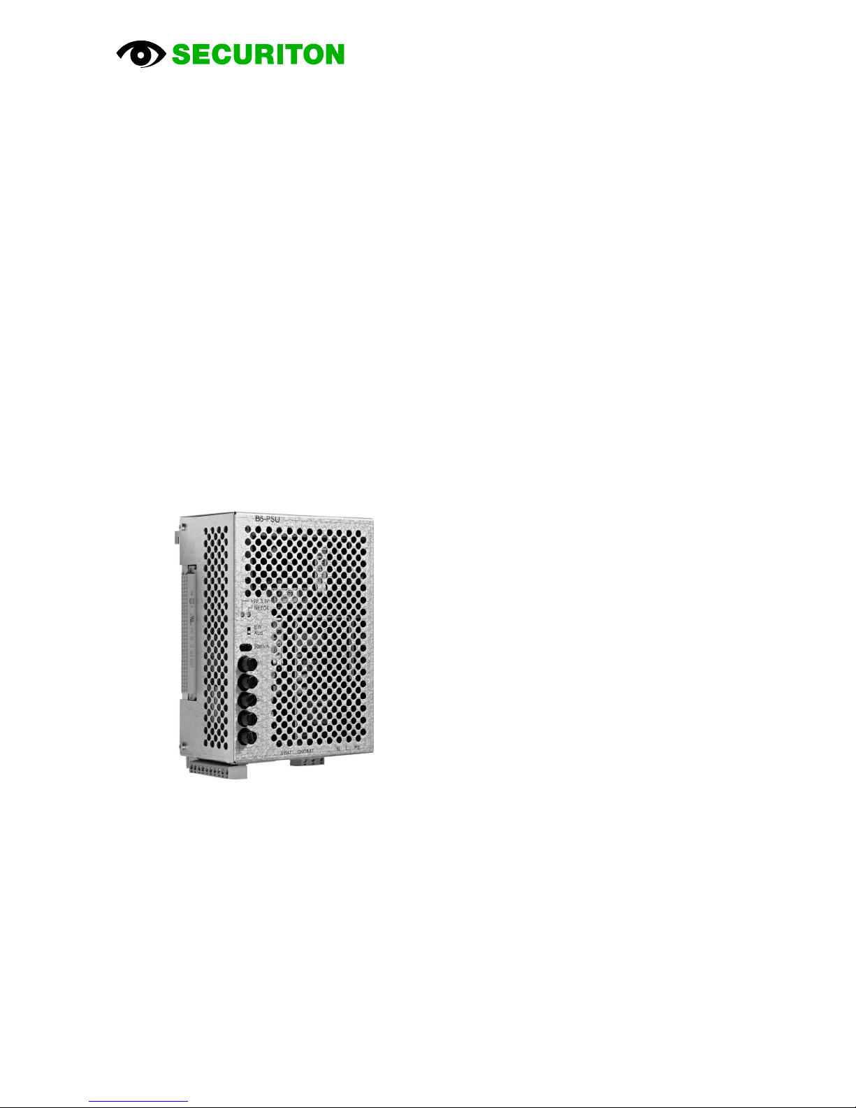
B6-PSU
Technical Description


Imprint
B6-PSU Power Supply Unit, Technical Description, T 811 039 en a 3 / 18
Imprint
Notice
This document, T 811 039, is valid only for the product described in Section 1.
This document is subject to change or withdrawal without prior notice. The validity of the statements made in this
document applies until the statements are revised by a new edition of the document (T number with new index).
The user of this document is responsible for staying up to date with its current status through the edi-
tor/publisher. We accept no responsibility for claims against any incorrect statements in this document which
were unknown to the publisher at the time of p
ublication. Handwritten changes and additions are not valid. This
document is protected by copyright.
Foreign language documentation as listed in this document is always released or changed at the same time as
the German edition. If there are inconsistencies between the foreign language documentation and the German
documentation, the German documentation is binding.
Some words in this document are highlighted in blue. These are terms and designations which are the same in
all languages and are not translated.
Users are encouraged to contact the editor/publisher if there are statements which are unintelligible, misleading,
incorrect, or if there are errors.
© Securiton AG, Alpenstrasse 20, 3052 Zollikofen, Switzerland
This document, T 811 039
1
, is available in the following languages: German T 811 039 de
English T 811 039 en
French T 811 039 fr
Current edition: Index a 08.06.2012 Rd
1
Reference document: B6-PSU, V 1.1

Safety information
4 / 18 B6-PSU Power Supply Unit, Technical Description, T 811 039 en a
Safety information
Provided the product is deployed by trained and qualified persons in accordance with technical document T 811 039 and the
danger, safety and general information notices in this technical documentation are observed, there is no danger to persons or
property under normal conditions and when used properly.
National and state-specific laws, regulations and guidelines must be observed and adhered to in all cases.
Below are the designations, descriptions and symbols of danger, safety and general information notices as found in this
document.
Danger
If the Danger notice is not properly observed, the product and other system parts may present a hazard for per-
sons and property, or the product and other system parts may be damaged to the extent that malfunctioning re-
sults in danger to persons and property.
•Description of which dangers can occur
•Measures and preventative actions
•How dangers can be averted
•Other safety-relevant information
Warning
The product may be damaged if the safety information is not heeded.
•Description of which damage can occur
•Measures and preventative actions
•How dangers can be averted
•Other safety-relevant information
Notice
The product may malfunction if this notice is not observed.
•Description of which malfunctions can be expected
•Measures and preventative actions
•Other safety-relevant information
Environmental protection / recycling
Neither the product nor product components present a hazard to the environment provided they are handled
properly.
•Description of which parts have environmental protection issues
•Description of how devices and their parts have to be disposed of in an environmentally-friendly way
•Description of the recycling possibilities
Batteries
It is not permitted to dispose of batteries in the domestic rubbish. As the end user you are legally obliged to re-
turn used batteries. Used batteries can be returned free of charge to the seller or brought to a designated recy-
cling point (e.g. to a communal collection point or retailer). You may also send them back to the seller by post.
The seller refunds the postage when you return your old batteries.

Document history
B6-PSU Power Supply Unit, Technical Description, T 811 039 en a 5 / 18
Document history
First edition Date 01 July 2011
Index „a“ Date 08.06.2012
Most important changes compared with first edition:
Section New (n) / changed (c) / deleted (d) What / Reason
•7 n Article SI-G 8A complement
Table of contents
Popular Power Supply manuals by other brands

Videx
Videx 520MR Installation instruction

Poppstar
Poppstar 1008821 Instructions for use

TDK-Lambda
TDK-Lambda LZS-A1000-3 Installation, operation and maintenance manual

TDK-Lambda
TDK-Lambda 500A instruction manual

Calira
Calira EVS 17/07-DS/IU operating instructions

Monacor
Monacor PS-12CCD instruction manual


