POWR2 POWRBANK-30.60/208V User manual

For use with the following models
•POWRBANK-30.60/208V
• POWRBANK-30.60/240V
Powr2 Ltd, Kemp House, 152 – 160 City Road
London EC1V 2NX
POWR2 POWRBANK User Manual V1.0 - 2019
www.powr2.com

Page 2 POWRBANK 30.60 US v1.0
www.powr2.com
POWR2 POWRBANK USER MANUAL
1 Introducon 4
1.1 Foreword 4
1.2 Convenons 5
1.3 Warnings 6
1.4 Disposal & Recycling 7
1.5 POWR2 Contact Details 7
1.6 About POWR2 7
2 Geng Started 8
2.1 Storage 8
2.2 Transporng, Liing and Posioning 8
2.2.1 Transportaon 8
2.2.2 Liing (Loading/Unloading) 9
2.2.3 Posioning 11
2.3 The POWRBANK Control Panel 12
2.4 The Busbar Panel 14
2.5 Connecng POWRBANK 15
2.5.1 Earth Connecon 15
2.5.2 Input Opons 15
2.6 Connect the main AC Input 16
2.7 Connecng to a Diesel Generator For Automac Stop/Start 17
2.7.1 Remote Generator Start Binding Posts Connecon 17
2.8 Seng Up a Diesel Generator to Be Part of a Hybrid System 17
2.8.1 Common Causes of Diesel Generator Startup Delays 17
2.9 Connect The AC Output 18
2.9.1 Connecng with output sockets 18
2.9.2 Connecng by Hard-Wiring Into The AC Output Busbar 18
2.10 Using POWRBANK as a Grid-Tied UPS 19
3 General Operaon 20
3.1 Turning the Power On 20
3.1.1 Turn ON sequence 20
3.2 Turning the Power O 20
3.2.1 Turn OFF sequence 20
3.3 Emergency Stop Buon 20
3.4 Power Assist 21
3.5 Monitoring and Controlling the POWRBANK using ECM 22
3.5.1 HOME Screen 22
3.5.2 GRID & SOLAR Screen 23
TABLE OF CONTENTS

Page 3
POWRBANK 30.60 US v1.0
www.powr2.com
POWR2 POWRBANK USER MANUAL
3.5.3 GENERATOR Screen 24
3.5.4 STORAGE Screen 26
3.5.5 LOAD Screen 27
3.5.6 LOAD CONTROL CONFIGURATION Screen 28
3.5.7 SYSTEM Screen 29
3.5.8 ALARMS Screen 31
3.5.9 HISTORICAL Data 33
4 Care And Maintenance 35
4.1 Charging the Unit: Caring For The Energy Storage 35
4.1.1 Performing Storage Maintenance 35
4.1.2 Rotaonal Storage Maintenance 36
4.2 Servicing 36
5 Safety & Protecon 37
5.1 Earthing POWRBANK 37
5.2 Safety Noce Regarding The Unit's Baeries 37
6 TroubleSHOOTING 39

Page 4 POWRBANK 30.60 US v1.0
www.powr2.com
POWR2 POWRBANK USER MANUAL
1 INTRODUCTION
1.1 Foreword
Thank you for purchasing your POWR2 POWRBANK.
The POWR2 POWRBANK is rental ready power supply that integrates with diesel generator systems to
optimize eciency and reduce noise, emissions and fuel waste.
ECM, the Energy Control Module is the brain of the unit, a touchscreen control panel enabling high-level
monitoring and control over the system.
POWR2 PORTAL, our Energy Management System (EMS) platform allows you to manage your eet. It
enables you to monitor and report on each unit and the entire eet at multiple levels to support the various
user groups you may have from end users to eet manages to service engineers. POWR2 PORTAL
provides the very best means of managing your energy storage allowing you to get the most out of the
system and respond to your customers’ needs more eectively.
This manual will take you through the steps needed to own and operate this equipment safely and
eectively. You will also be able to manage and maintain the asset throughout its operational life.
POWR2 provides a one year return to base warranty on all its equipment. We oer various levels of service
contracts designed to suit your needs so please contact us about your requirements.
Thank you for choosing POWR2 and we look forward to working alongside you on this energy journey
towards a cleaner safer future.
Page 5
POWRBANK 30.60 US v1.0
www.powr2.com
POWR2 POWRBANK USER MANUAL
1.2 Conventions
Throughout this user manual, the following symbols are used:
WARNING
This symbol warns of the presence of a dangerous voltage
which could cause harm to the operator or others.
This symbol indicates the potential of damage to the unit or
connected devices.
This symbol indicates important or useful information.
The following terms are used in this manual to provide greater clarity:
• POWR2 will be referred to as “The Manufacturer”.
• The POWR2 Hybrid Energy System will be referred to as “POWRBANK” or “Unit”.
• Any AC input or supply to the POWRBANK will be referred to as "AC source".
• Any items that consume power will be referred to as “Loads”.
• POWRBANK internal power electronics will be referred to as "Inverter"
• Solar Charge Controller will be referred to as "MPPT".

Page 6 POWRBANK 30.60 US v1.0
www.powr2.com
POWR2 POWRBANK USER MANUAL
1.3 Warnings
This user manual is an important part of POWRBANK. It
must be available to all operators and kept close to the unit
so that it can be referred to at any time.
WARNING
When the unit is operating it generates potentially lethal
voltages. Work must only be performed on the unit by the
manufacturer or a qualied service engineer approved by
the manufacturer.
All items connected to the unit including distribution cables
and boxes should be regularly checked and adhere to the
same local regulations and standards as a regular grid-tied
mains installation.
Page 7
POWRBANK 30.60 US v1.0
www.powr2.com
POWR2 POWRBANK USER MANUAL
1.4 Disposal & Recycling
POWRBANK comprises of components that must be disposed of responsibly. For environmental purposes,
many of the components within the unit can be recycled or reused. POWR2 will ensure the safe
decommissioning and recycling of the unit at no charge if the unit is returned to the manufacturer. Otherwise,
please contact the manufacturer for more information on safe and proper decommissioning of your
POWRBANK.
1.5 POWR2 Contact Details
POWR2
4 Duke Place
Norwalk
CT 06854
USA
Tel: 1-800-354-4502
E-mail: [email protected]
Web: www.powr2.com
1.6 About POWR2
POWR2 are dedicated to developing and marketing solutions that give our clients a competitive edge with
ground breaking oerings and new industry best practices. The POWRBANK has been designed by a team
of industry experts who have had 10 years’ experience in the renewable and energy storage sector.
POWR2 designs and builds Energy Storage Systems that seamlessly connect to solar PV, mains grid and
diesel generators to optimize performance and eciency.
The team have engineered state of the art systems that are robust, cost eective and reliable. Over the
course of our evolution we have evaluated and tested countless designs, components and suppliers. We
currently manage a diverse and complex supply chain of over fty manufacturers providing more than one
hundred and twenty separate components.
We apply strict quality control methods to every aspect of the process, from design, to procurement, to
manufacture, assembly and to testing.
The organization is built around our core values of eciency, innovation, integrity and customer service of
which helps us create a long term sustainable business.
We believe that everyone wants to grow and become a better person. Our team is family, we want to
support, train, stretch and develop each one so they have the competitive advantage and are the winning
team.

Page 8 POWRBANK 30.60 US v1.0
www.powr2.com
POWR2 POWRBANK USER MANUAL
2 GETTING STARTED
2.1 Storage
1. The internal energy storage must be maintained while the unit is not in use. See "4.1 Charging
the Unit: Caring For The Energy Storage" on page 35.
2. POWRBANK is designed to be used and stored outside. However, it is recommended that the
unit is stored undercover when possible to prevent unnecessary weathering.
2.2 Transporting, Lifting and Positioning
2.2.1
Be sure to double check the capacity of lifting equipment
before lifting the unit.
Transportation
Powr2 oers no direct support for untrained individuals
carrying out any action on the unit. Please, contact Powr2
to request a trainning.
WARNING
1. POWRBANK can be transported using a trailer or goods
vehicle with adequate available payload. Check the relevant
transportation documentation for suitability.
2. The gross weight of the unit can be found on the rating plate
positioned on the central front door.
3. It is recommended that the unit is secured using suitable
straps when in transit to prevent it from moving.
4. Unit must be switched o through the ECM System switch
button on home tab.
5. Check that the emergency stop button is not engaged by
twisting it clockwise.
Page 9
POWRBANK 30.60 US v1.0
www.powr2.com
POWR2 POWRBANK USER MANUAL
It is the user's responsibility to check local regulations for
transport of POWRBANK as it contains lithium-based batteries.
2.2.2 Lifting (Loading/Unloading)
Fig. 1 - Lifting Ring Warning
1. POWRBANK must be loaded or unloaded using the correct equipment operated by suitably
trained personnel.
2. Using the fork pockets, POWRBANK can be loaded or unloaded with a suitable fork-lift truck
or telehandler.
Always check the rating plate to ascertain the gross weight
of the unit.
The unit must remain upright at all times.
Page 10 POWRBANK 30.60 US v1.0
www.powr2.com
POWR2 POWRBANK USER MANUAL
Achor Point Application Assembly Safety
• Always select proper load rated lifting device for use with Anchor Point.
• Attach lifting device ensuring free t to Anchor Point bail (lifting ring).
• Apply partial load and check proper rotation and alignment. There should be no interference between
load (work piece) and Anchor Point bail.
Anchor Point Inspection / Maintenance
• Always inspect Anchor Point before use.
• Regularly inspect Anchor Point parts.
Maintenance, Checks, Repairs
• Never use Anchor Point that shows signs of corrosion, wear or damage.
• Never use Anchor Point if bail is bent or elongated.
• Always be sure threads on shank and receiving hole are clean, not damaged, and t properly.
• Always check with torque wrench before using an already installed Anchor Point.
• Always make sure there no spacers (washers) used between bushing ange and the mounting
surface. Remove any spacers before use.
• Always ensure free movement of bail. The bail should pivot 180 degrees and swivel 360 degrees.
• Loads may slip or fall if proper Anchor Point assembly and lifting
procedures are not used.
• A falling load may cause serious injury or death.
• Do not use with damaged slings, chain or webbing.
• Use only YOKE parts as replacements.
ANCHOR POINT
WARNING
Page 11
POWRBANK 30.60 US v1.0
www.powr2.com
POWR2 POWRBANK USER MANUAL
2.2.3 Positioning
Ensure that the exhaust and hot air ow of diesel generators
are directed away from POWRBANK.
1. The unit must be positioned upright on a at, solid surface. Ensure that the unit is not at risk of
being submersed in water above the fork pockets.
2. The unit should be positioned as close as possible to the chosen input source (e.g. diesel
generator) and where applicable, close to its earth point.
3. At least 3 feet should be allowed for ventilation on all sides of the unit.
4. Ensure that vents are not obstructed and heat sources are not directed at the unit.
Page 12 POWRBANK 30.60 US v1.0
www.powr2.com
POWR2 POWRBANK USER MANUAL
2.3 The POWRBANK Control Panel

Page 13
POWRBANK 30.60 US v1.0
www.powr2.com
POWR2 POWRBANK USER MANUAL
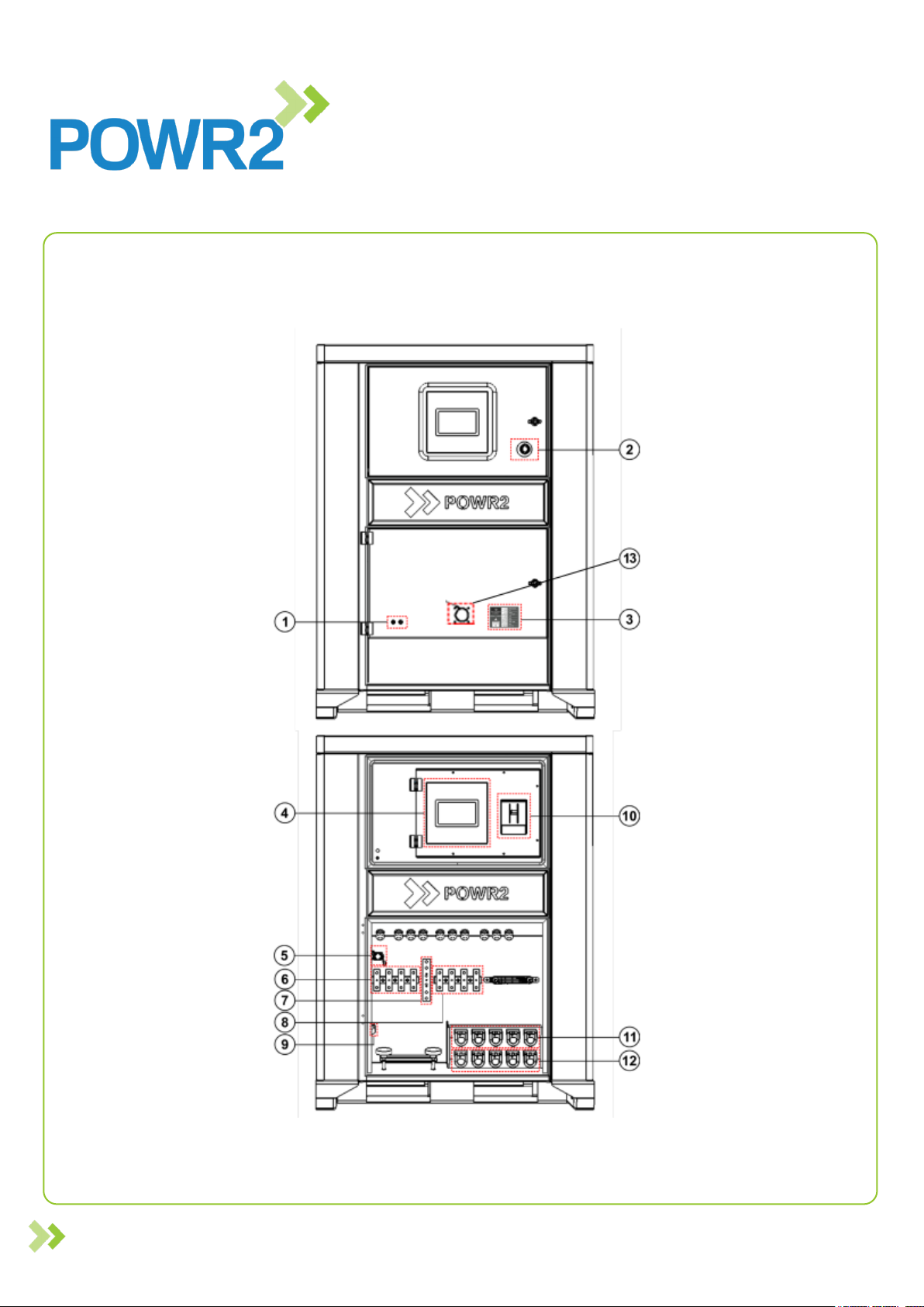
Fig. 2 - Control Panel
1. Generator Remote Start Binding posts for connecting wires to send start and stop signals to a
connected diesel generator (circuit is normally open).
2. Emergency stop Press in to immediately shut down AC Output.
3. Rating Plate Provides specication and details of the Powrbank.
4. ECM Controller The brain of the Powrbank; interfaces with and controls the various system
components whilst data logging and connecting with the cloud platform.
5. Safety Limit Switch Switches o the AC Output when the bottom distribution door has been
opened.
6. Input Busbar Power Terminals 208V/250A 3-Phase or 240V/250A Split Phase power input
terminals for the unit.
7. Earth Busbar Earth Input/Output terminal for the unit.
8. Output Busbar Power Terminals 208V/250A 3-Phase or 240V/250A power output terminals for
the unit.
9. Generator RS485 Bus Terminals for connecting the RS485 Bus from a generator control panel
to the node controller.
10. Output circuit breaker 250A 3-Phase or 250A Split Phase / Master Circuit Breaker. Provides
overload protection to the Powrbank outputs.
11. Input CAM Connectors 208V/250A 3-Phase or 240V/250A inlets.
12. Output CAM Connectors 208V/250A 3-Phase or 240V/250A outlets.
13. Panel Mount CEE-Form Inlet 208V/30A 3-Phase or 240V/30A grid connection when unit at
depot

Page 14 POWRBANK 30.60 US v1.0
www.powr2.com
POWR2 POWRBANK USER MANUAL
2.4 The Busbar Panel
The Busbar panel is located behind the lower distribution door. It is accessed by opening the lock at the
right of the door.
Fig. 3 - 3-Phase Busbar Panel (Listed left to Right)
1. AC Input Busbar - (L1,L2,L3,N) For attachment of 10 mm ring terminals.
2. Earth Busbar - Earth connection for 10 mm ring terminals.
3. AC Output Busbar - (L1,L2,L3,N) For attachment of 10 mm ring terminals.
Fig. 4 - Split Phase Busbar Panel (Listed left to Right)
1. AC Input Busbar - (L1,L2,N) For attachment of 10 mm ring terminals.
2. Earth Busbar - Earth connection for 10 mm ring terminals.

Page 15
POWRBANK 30.60 US v1.0
www.powr2.com
POWR2 POWRBANK USER MANUAL
3. AC Output Busbar - (L1,L2,N) For attachment of 10 mm ring terminals.
Fig. 5 - Busbar Connection Diagram
2.5 Connecting POWRBANK
2.5.1 Earth Connection
WARNING
A protective earth must be connected to POWRBANK in
compliance with applicable local standards and regulations.
When the unit is connected to an AC source, a separate earth connection should not be connected to the
earth busbar, only when working as stand alone. Refer to "Fig. 3 - Busbar Panel" on page 14.
2.5.2 Input Options
The unit can accept input from a 3-phase AC power source or a Split phase AC power source depending
on its conguration. Further information on connecting an AC Input is provided in section "2.6 Connect the
AC Input" on this page.
The AC Input current is adjustable if Operation mode is selected. If POWRBANK is in Maintenance mode,
AC Input current is limited allowing the unit to be charged from AC sources with lower current capacities.
See "Genset Current Limit" on page 23.
NoItem
1 M10 Plain Nut
2 M10 Split Washer
3 M10 Flat Washer
4M10 Ring Terminal
5Busbar
6 M10 Flat Washer
7 M10 Bolt
Page 16 POWRBANK 30.60 US v1.0
www.powr2.com
POWR2 POWRBANK USER MANUAL
WARNING
The unit will only accept 208V 3-Phase / 240V Split Phase
according to its conguration. If a dierent type of input is used
it could severely damage the system and this will invalidate the
product warranty!
2.6 Connect the main AC Input
1. Ensure that the circuit breaker of the AC source being connected to the unit is switched OFF.
2. Turn inverters OFF on the ECM onboard screen by selecting OFF mode (Home tab-System OFF)
3. Switch OFF the output circuit breaker.
4. Open the lower distribution door. See "2.3 The POWRBANK Control Panel" on page 10.
5. Ensure the power terminals are dry; wipe o any excess moisture with an absorbent cloth.
6. Attach the AC supply connectors to the inlet connectors or ring terminals to power terminals.
7. Close the lower distribution door.
8. Turn the inverters ON on the ECM onboard screen by selecting Operation mode (Home tab-System
ON).
9. Switch on the AC input’s power supply.

Page 17
POWRBANK 30.60 US v1.0
www.powr2.com
POWR2 POWRBANK USER MANUAL
2.7 Connecting to a Diesel Generator For Automatic Stop/Start
A Remote Generator Start function is provided to automatically control a diesel generator. The Start and Stop
conditions are programmed using the ECM.
2.7.1 Remote Generator Start Binding Posts Connection
Remote Generator Start terminals are located on the bottom door. See "Fig. 2 - Control Panel" on page 13.
This is a connection that is used to send a start or stop signal to a remote fuel powered generator using its auto-
start lead.
2.8 Setting Up a Diesel Generator to Be Part of a Hybrid System
When setting up a hybrid system the overall performance of combining POWRBANK with the diesel generator
can be enhanced by making some simple adjustments to the diesel set.
In automatic mode some diesel sets will start and run as soon as a start signal is received, however some have
a number of delays which can hinder the diesel generator from starting up and generating power as quickly as
possible. These delays should be minimized wherever practical.
2.8.1 Common Causes of Diesel Generator Startup Delays
2.8.1.1 Start Delay
This delay allows for short "false start" signals and can be as long as ve seconds, when used with the hybrid
unit it is important that the diesel generator starts immediately. Where possible this delay should be removed.
2.8.1.2 Pre-Heat Delay, Safety On Timer & Warm Up Timer
Always try to reduce the delays to the minimum acceptable level.
2.8.1.3 Automatic Mode
Ensure diesel generator is switched to automatic mode.

Page 18 POWRBANK 30.60 US v1.0
www.powr2.com
POWR2 POWRBANK USER MANUAL
2.9 Connect The AC Output
2.9.1 Connecting with output sockets
1. Turn inverters OFF on the ECM onboard screen by selecting OFF mode (Home tab-System OFF).
2. Ensure that the output circuit breaker is switched OFF (DOWN position). See "2.3 The
POWRBANK Control Panel" on page 10.
3. Ensure that breaker on the AC source is OFF.
4. Open the lower distribution door. See "2.3 The POWRBANK Control Panel" on page 12.
5. Ensure that the sockets are dry; wipe o any excess moisture with an absorbent cloth.
6. Plug the Load(s) in to the Output Sockets. See "2.3 The POWRBANK Control Panel" on page
12.
7. Close the lower distribution door.
2.9.2 Connecting by Hard-Wiring Into The AC Output Busbar
1. Turn inverters OFF on the ECM onboard screen by selecting OFF mode (Home tab-System OFF).
2. Ensure that the output circuit breaker is switched OFF (DOWN position). See "2.3 The
POWRBANK Control Panel" on page 10.
3. Ensure that breaker on the AC source is OFF.
4. Open the lower distribution door. See "2.3 The POWRBANK Control Panel" on page 12.
5. The Output Busbar is located centrally and is the right hand set comprising of 4 terminals. See
"2.3 The POWRBANK Control Panel" on page 12.
6. Ensure that the power terminals are dry; wipe o any excess moisture with an absorbent cloth.
7. Ensure that the cable used is suitable for the application.
8. Connect to the lower row of connections using 10 mm ring terminals.
9. Remove the M10 nuts and two washers.
10. Attach ring terminals in the correct order, referring to "Fig. 3 - Busbar Panel" on page 14.
11. See "Fig. 4 - Busbar Connection Diagram" on page 15 for a diagram of the Busbar terminal
xings.
12. Close the lower distribution door.

Page 19
POWRBANK 30.60 US v1.0
www.powr2.com
POWR2 POWRBANK USER MANUAL
2.10 Using POWRBANK as a Grid-Tied UPS
POWRBANK can be used as a backup power supply or as an oine uninterruptible Power Supply (UPS). In
the event of a grid failure or supply power failure, POWRBANK will continue to supply power on its output circuits.
The changeover is less than 20 ms with minimal or no interruption to the output supply, so there will be no
disruption to electronic devices, etc.
The changeover is automatic, requires no intervention from the user, and will continue until POWRBANK's energy
storage is depleted or the supply returns. When the supply is re-established, the storage will recharge
automatically.
Page 20 POWRBANK 30.60 US v1.0
www.powr2.com
POWR2 POWRBANK USER MANUAL
3 GENERAL OPERATION
3.1 Turning the Power On
Once all connections are complete, the unit is ready to be switched on.
3.1.1 Turn ON sequence
1. Ensure that the lower distribution door is closed.
2. Switch ON the output circuit breaker (UP position).
3. Turn the inverters ON on the ECM onboard screen by selecting Operation mode (Home tab-System
ON).
4. The load metrics can now be observed on the ECM and Powr2 Portal.
3.2 Turning the Power O
When Power is not needed at the output, the unit can be turned o.
3.2.1 Turn OFF sequence
1. Turn inverters OFF on the ECM onboard screen by selecting OFF mode (Home tab-System OFF).
2. Switch OFF the input and output circuit breaker (DOWN position)
3.3 Emergency Stop Button
ONLY use the emergency stop button in an emergency.
1. If there is an emergency and it is necessary to turn o the unit's power, depress the Emergency
Stop Button on the Upper Door.
2. The unit will then shut down. POWRBANK can not be switched on again until the Emergency
Stop Button is released by rotating it clockwise.
3. Once the problem has been rectied, follow the instructions in "3.1 Turning the Power On" on
page 17 to switch the power back on.
This manual suits for next models
1
Table of contents


