Integra Luxtec MLX 300 Operation manual

OPERATION AND SERVICE MANUAL
Integra® Luxtec® MLX 300 Wa
For use with ACMI, Wolf, Storz and Olympus Fiber Cables
EN
Integra®Luxtec®
MLX 300 Wa Xenon Light Source

Integra® Luxtec®
MLX 300 Wa Xenon Light Source

2
Table of Contents
Indications for Use .............................................................................................................................................................................................. 3
Symbols .................................................................................................................................................................................................................4
General Warnings................................................................................................................................................................................................. 5
Precautions ...........................................................................................................................................................................................................5
Overview ...............................................................................................................................................................................................................6
Operation ..............................................................................................................................................................................................................6
Xenon Lamp Module Replacement ..................................................................................................................................................................8
Fuse Replacement ................................................................................................................................................................................................9
Optional Floor Stand Assembly........................................................................................................................................................................ 10
Replacement Parts and Accessories.................................................................................................................................................................. 11
Maintenance and Cleaning ............................................................................................................................................................................... 11
Troubleshooting ................................................................................................................................................................................................ 12
Specifications ......................................................................................................................................................................................................13
Electromagnetic Compatibility (EMC) User Information ............................................................................................................................ 14
Block Diagram......................................................................................................................................................................................................17
Repair and Return............................................................................................................................................................................................... 18
Limited Warranty ............................................................................................................................................................................................... 18

CAUTION: FEDERAL (USA) LAW RESTRICTS THIS DEVICE TO SALE BY OR ON THE ORDER OF A PHYSICIAN
Indications for use
The Integra®Luxtec® MLX Light Source is designed to supply high intensity white light through a fiber optic cable for
illumination of a surgical field during a surgical and/or medical procedure.
The Integra Luxtec MLX Light Source should never be used in ocular surgery or in a surgical procedure requiring
direct illumination of the eye.
This device is intended to be used by professional healthcare users.
Integra® Luxtec®
MLX 300 Wa Xenon Light Source
3

Symbols
Found on a medical grade light source, other illumination related equipment, fiber optic cables and corresponding packaging.
Caution
Fuse
Type CF Equipment
Type BF Equipment
Brightness
Motor
Fan
Certified by CSA
Consult Instructions for Use
Part Number
Batch Code
Serial Number
Authorized Representative in the European Community
Manufacturer
Date of Manufacture
This device meets CE requirements
Caution: High Voltage
Equipotentiality
Protective Earth
On / Off
Stand-by
System Status Display
System
Do Not Dispose
Humidity Limitation
Alternating Current
Temperature Limitation
Atmospheric Pressure Limitation
Push
Hours
Over Temperature
Intensity
Lamp
Keep dry
REF
LOT
EC REP
0123
4
Refer to Instruction Manual
High Temperature

5
• SAFETY PRECAUTIONS MUST ALWAYS BE EXERCISED WHEN
USING ELECTRICAL EQUIPMENT TO PREVENT OPERATOR/
PATIENT SHOCK, FIRE HAZARD OR EQUIPMENT DAMAGE.
• FIRE HAZARD: DO NOT DRAPE OR COVER THE LIGHT
SOURCE WHILE IT IS OPERATING.
• Before every procedure, carefully inspect the light source to
ensure it has been properly maintained and cleaned, and that
it is fully functional. DO NOT use if inspection reveals any
damage such as case damage or loose connectors.
• Follow the instructions of other manufacturer’s equipment
when used in conjunction with this product.
• To avoid risk of electric shock, this equipment must only be
connected to a supply mains with protective earth.
• To reduce the risk of fire and electric shock, do not expose
electrical equipment to moisture. When cleaning, do not
immerse any electrical device in liquid.
• Do not use or store liquids on or above the light source.
• Electric shock hazard. If unit is not functioning properly, DO
NOT OPEN. Please refer to the Repair and Return Section of
this Manual.
• All electrical equipment must be used with approved hospital
grade power cords and power plugs inserted properly into
grounded AC power outlets. If replacement is necessary,
replace only with approved power cord.
• The light source should never be used in ocular surgery or in
a surgical procedure requiring direct illumination of the eye.
• Use care not to point any fiber optic cable directly at the eye
while operating the light source.
• The light source produces high intensity light. Thermal burns
can result from improper use of the light source or from the
light output of the fiber optic cable.
• Explosion Hazard. Do not use in an oxygen rich environment
or in the presence of flammable anesthetics, liquids, vapors,
gases or dusts.
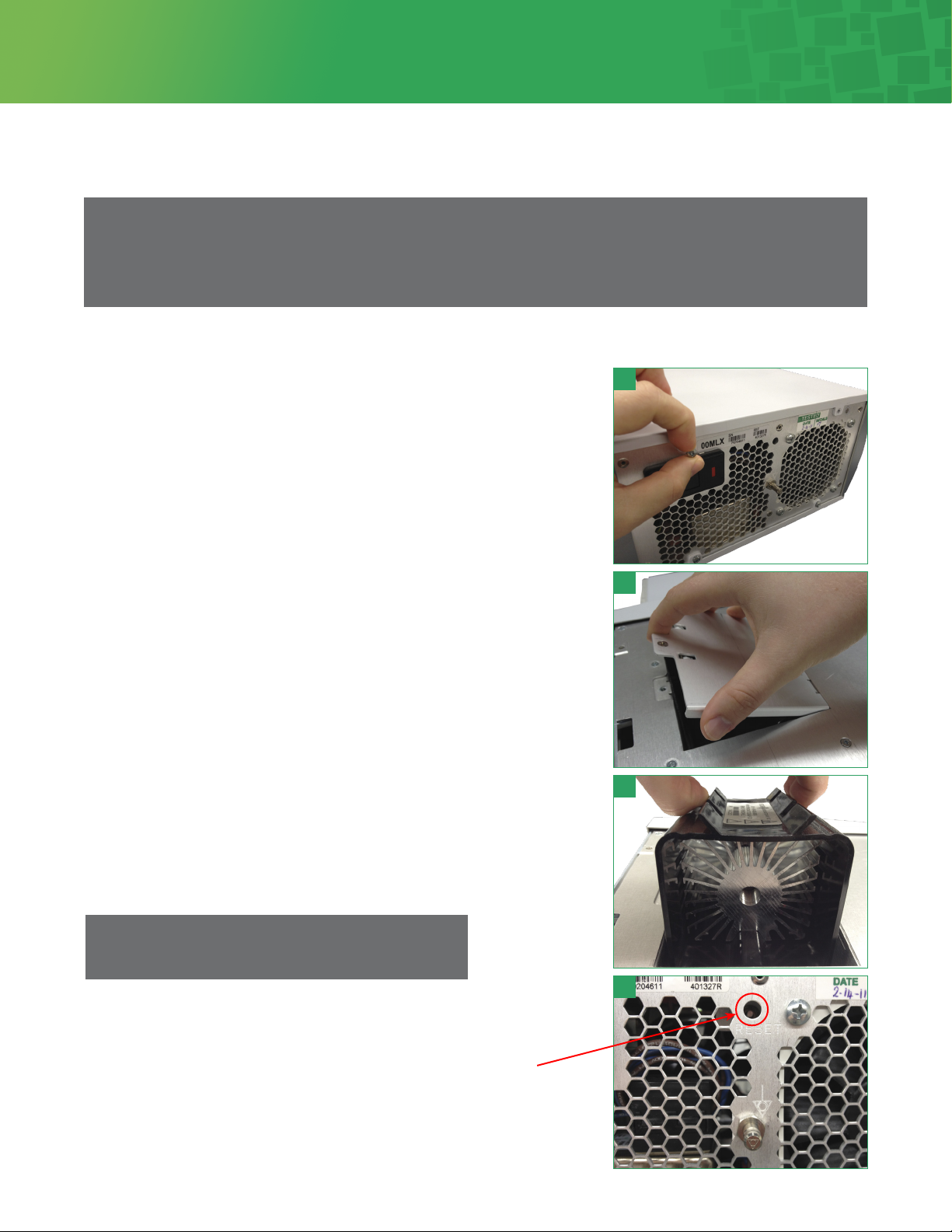
• Keep cooling vent and fans free of obstructions.
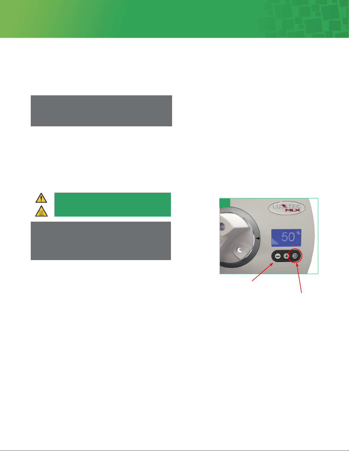
• When light source is not in use, turn off the power or put the
unit in stand-by mode.
• Ensure that the fiber optic cable matches the port type
to prevent damaging the optical components of the light
source. For user convenience, the light source has a turret
with labeled selectable ports.
• Do not use the headlight at distances of less than 10” (25cm).
• Warning: No modification of this equipment is allowed.
• Do not position the equipment so that it is difficult to
remove the power plug.
Precautions
• Take precautions to verify that the fiber optic cable is
appropriately suited for the light source. Xenon and other
high illumination light sources require premium fiber optic
cables in order to achieve optimal performance and prevent
damage to the fibers, thereby diminishing the quality of the
light output or the useful life of fiber optic cable. Use only
fiber optic light guide cables with the correct proximal fiing
for your turret and approved and tested for compatibility
with high intensity Xenon lamps of 300W or higher.
• Take precautions not to touch or disconnect the cable end
fiing from the turret until the Light Source has been “shut
down” for a period of time and allowed to cool. The cable
end fiing will remain hot immediately following shut down,
which can cause burns.
• Take precautions to not place and rest a hot cable end fiing
and/or head light on a patient or allow the system to come
in contact with un-protected hands or tissue. The entire
system should be allowed to cool following use. Failure to do
so can cause burns and/or tissue damage.
General Warnings
The user should carefully study the Operation and Service Manual before using the equipment in a clinical environment. This
Manual contains information about the proper procedures for preparing this product for its use and care. Instructions should
be followed, with special aention given to warnings, controls and user specifications. The Manual should be available to the
appropriate personnel.
Integra® Luxtec®
MLX 300 Wa Xenon Light Source

6
The MLX light source delivers 300 was of cool white infrared (IR) filtered light. The lamp is housed in a lamp module that can
be easily serviced without special tools.
Set Up And Inspection Before Use
The light source comes with the hospital grade power cord packaged separately. Verify that both components are in good
condition.
This device should be used in environments that meet the operating environmental conditions in the specification section of
this manual.
Before turning power on to the light source, make sure the unit is plugged into any standard 100VAC to 240VAC 50-60Hz
(as appropriate) outlet. Grounding reliability is guaranteed only when connected to a “hospital grade” receptacle.
Allow a minimum of 2 inches (5.08 cm) clearance at the rear and sides of the unit for cooling air flow. Ensure that the unit is not
near air exhaust or against other equipment.
Operation
1. Insert a fiber optic cable in the proper port in the turret. The active port is indicated by a le facing arrow on the perimeter
of the turret (See Figure 1). Available ports are ACMI, Olympus, Storz and Wolf cable-compatible. All ports are identified
appropriately.
2. Press the Power Switch in the upper le corner of the front panel (See Figure 2).
3. When the Power Switch is pressed the Stand-by Light (Figure 3) will blink and there will be a 3 – 4 second delay before the
Xenon Lamp illuminates while the system does a self-diagnostic check.
4. Press the Stand-by Buon.
Overview
1 2 3
Warning
The MLX light source monitors air intake temperature
and will turn off if ambient temperature is > 40 C

5. The system will start up at the same light intensity as when last used. For new systems, the light intensity will start at the
minimum 20% seing.
6. To adjust the light intensity, push the Membrane Switches (Figure 4): + to increase or - to decrease the light output or
intensity. Range is 0%, 20 – 100% in 5% increments. Holding the + or – buon will change the intensity more quickly.
7. The System Status Display can be pressed to show both lamp time and system operation time. A second press of the switch
will show the soware version of the system monitor. A third press returns to light output. (The system will automatically
return to the light intensity reading aer 15 seconds).
8. The system may be placed in and out of stand-by mode by using the stand-by switch. The system will emit no light in this
state and allow the surgeon to unplug a headlight, move around the table, or change cables in a laparoscopic or
endoscopic procedure.
9. Take precautions not to touch or disconnect the cable end fiing
from the turret until the light source has been “shut down” for a period
of time and allowed to cool. The fiber optic cable end fiing will remain
hot immediately following shut down, which can cause burns.
10. To shut the system off, simply press the main Power Switch as in Step 2.
Note
It is strongly recommended that the light be used at the
minimum intensity for good visualization.
Note
If unit is le in stand-by mode for 15 minutes, it
will automatically shut off the lamp. Fans will keep
running. To re-activate, push the Stand-by Buon.
Caution
Fiber Optic Cable end fiing can be hot
7
Integra® Luxtec®
MLX 300 Wa Xenon Light Source
membrane switches
system status display
4

8
To remove lamp:
1. Make sure the power is off and the hospital grade power cord is disconnected.
2. Remove the retaining screws from the top plate (Figure 5) and retain screws.
3. Slide the top plate towards the back of the unit until it stops.
4. Li the top cover up and off the unit.
5. Unscrew the lamp module door and remove (Figure 6) and retain screw.
6. Grasp the module by the tabs and pull directly up (Figure 7).
5
7
6
8
Xenon Lamp Module Replacement
Note
Please adhere to appropriate safety precautions when performing lamp replacement. Only qualified personnel should
service this device. Protective facemask and/or proper safety glasses should be worn when replacing the lamp module.
Before changing the lamp module, turn power off and allow the light source to cool for at least fieen (15) minutes.
Please read and comply with all Precautions and General Warnings listed in this manual.
To replace lamp:
1. Orient the lamp module (P/N 001320LX) to face forward.
2. Place the module into the light source.
3. Seat module securely.
4. Replace the lamp module door and secure it with the screw.
5. Align top cover brackets into slots and slide forward.
6. Slide the top plate forward until it engages the front panel.
7. Replace the retaining screws in the rear panel.
8. Replace the hospital grade power cord and turn on power to verify operation.
To reset lamp age meter:
1. Using the membrane switch, turn the display to the lamp age/system age screen.
2. On the rear of the unit insert a pen/pencil or other suitable pointed object into
the slot marked RESET (Figure 8).
3. Push until a click is felt.
4. Verify that the lamp age has been reset to 0.
Note
The System Age reading CANNOT be reset.
RESET

9
The fuses for the light source are located in the power entry module in the rear
of the unit and may require replacement if the system does not respond to the
power switch.
To replace a fuse:
1. Remove the hospital grade power cord from the back of the light source.
2. Using a small flat screwdriver, pry open the retaining door (Figure 9) and
pry out the red plastic block from the power entry module (Figure 10).
3. Check to see if either fuse is blown; if blown, replace with a fuse of the
same rating (Integra P/N 600987).
4. Replace the red block in the housing.
5. Snap the retaining door into place.
6. Plug cord back into light source and retest the unit.
Fuse Replacement
9
10
Integra® Luxtec®
MLX 300 Wa Xenon Light Source

10
The floor stand assembly includes the following components along with the necessary Phillips head screwdriver:
1. Base with five (5) casters (2 locking)
2. One column with light source base plate
3. Handle
4. MLX light source base
Floor stand assembly instructions:
1. With the handle positioned so that the Luxtec logo is properly aligned, slide the handle onto the column and
center the handle about 5 inches (13cm) below the light source base plate. Tighten handle screw to hold in place.
2. Insert assembled column into the base. Seat firmly.
3. Aach the light source base onto the base plate (Figure 11) with the four (4) screws provided, using the Phillips
head screwdriver provided.
4. Secure the light source to base plate by aligning the feet to the holes on the surface of the plate. Tighten the two screws on
the boom of the plate to the light source (Figure 12).
Optional Floor Stand Assembly
Figure 11
Figure 10
Figure 11
Figure 10
11
12

11
Replacement Parts And Accessories
Maintenance and Cleaning
To place an order, contact your local Integra distributor or call Integra Customer Service at 1-800-431-1123
(USA & Canada only) or +1-914-789-7094 to identify your local Integra representative.
• Allow unit to cool for at least 15 minutes prior to cleaning.
• Unplug the power cord before cleaning. The light source exterior can be cleaned and disinfected using 70% isopropyl
alcohol. Allow 5 minutes for alcohol to evaporate before reconnecting to power.
• Use a vacuum cleaner and a so brush to remove visible dust accumulation from fan and vent holes whenever necessary and
always when replacing the lamp.
Reference
Reference
Reference
Light Source
Accessories
Optional Accessories
00MLX 300 Wa Xenon Light Source with Turret (ACMI, Wolf, Storz and Olympus)
001320LX Xenon Lamp Module
600987 Fuse 6.3 Amp, Slow Blow
AX2100BIF UltraLite® Pro headlight with 9 (275cm) premium bifurcated cable, Mark II module and gown clips.
001337 MLX Floorstand
601949EUR6 European Power Cord 20’ (6m)
601949UK6 Hospital Grade UK Power Cord 20’ (6m)
601949US6P1 Hospital Grade USA Power Cord 20’ (6m)
Description
Description
Description
Integra® Luxtec®
MLX 300 Wa Xenon Light Source

12
Troubleshooting
Trouble Area Possible Cause Corrective Action
No power Light source not plugged in Plug in light source
Top cover not closed Close and secure top cover
System overheated Contact Integra for service
NOTE: System may cycle on/off if le plugged
in and powered
No light output Light source not turned on Turn power on
Bad/no lamp Check lamp seating/replace lamp module
Aenuator closed Verify not in standby mode
Turret mispositioned Rotate turret to desired adapter fiing
Blown fuse Replace fuse as indicated in maintenance section
Cooling system obstructed Clear obstructions, cycle power
System overheated Contact Integra for service
NOTE: System may cycle on/off if le plugged
in and powered
System shuts down
during use
Cooling system obstructed Clear obstructions, cycle power
System overheated Contact Integra for service
NOTE: System may cycle on/off if le plugged
in and powered
Lamp shroud shows signs
of melting
Cooling system obstructed Clear obstructions, cycle power
System overheated Contact Integra for service
NOTE: System may cycle on/off if le plugged
in and powered
Reduced Light Output Cable mismatched to turret Rotate turret to matching adapter fiing
Aenuator mispositioned Verify not in standby mode
Bad lamp Replace lamp module
Fault Symbol Possible Cause Corrective Action
Lamp change (will blink aer
1000 hours)
Change lamp. Module Part number 001320LX
Fan failure Shut off system to reset. If it does not reset contact Integra for service
Lamp overheat Shut off system to reset. If it does not reset contact Integra for service
Aenuator motor failure Shut off system to reset. If it does not reset contact Integra for service

13
Specifications
Lamp
Type Xenon Short Arc Lamp
Waage 300 Was
Lamp Life 1000 Hours
Light Source
Dimensions 15.4”L x 11.2”W x 5.9”H (390mm L x 285mm W x 150mm H)
Weight 12.5 lbs. (5.7 kg)
Power Input 100~240VAC, 50/60Hz, 6.3A
Fuses (2) 6.3A, 250VAC, 5x20 mm, Slo-Blo, IEC Standard
Protection Class Class 1
AC Power Leakage Leakage current to chassis (with ground wire intact), less than 100 microamps
Leakage current to chassis (with ground wire interrupted), less than 500 microamps
Applied Part Classification Type CF
Electrical Safety Conforms to UL 60601-1, IEC 60601-1, and
CSA C22.2 NO. 601.1
Electromagnetic Compatibility IEC60601-1-2
Environment:
Storage Temperature
Operating Temperature
Storage Humidity
Operating Humidity
0 to 50°C (32 to 122°F)
10 to 40°C (41 to 104°F)
10 to 85% non-condensing
Atmosphere Pressure:
Storage
Operating
500 to 1060hPa
700 to 1060hPa
Power Cord Hospital grade
Mode of Operation Continuous
Ingress Protection IP20
Power Dissipation 450 Was
Integra® Luxtec®
MLX 300 Wa Xenon Light Source

14
Electromagnetic Compatibility (EMC) User Information
Warning
Medical Electrical Equipment needs special precautions regarding EMC and needs to be installed and
put into service according to the Electromagnetic Compatibility [EMC] information provided in the
accompanying documents.
Warning
Portable and Mobile RF Communications Equipment can affect Medical Electrical Equipment.
Warning
The equipment or system should not be used adjacent to or stacked with other equipment. If adjacent
or stacked use is necessary, the equipment or system should be observed to verify normal operation in
the configuration in which it will be used.
Note
The EMC tables and other guidelines that are included in the Instruction Manual provide information to the customer
or user that is essential in determining the suitability of the Equipment or System for the Electromagnetic Environment
of use, and in managing the Electromagnetic Environment of use to permit the Equipment or System to perform its
intended use without disturbing other Equipment and Systems or non-medical electrical equipment.
Table 201: Guidance and Manufacturer’s Declaration – Emissions All Equipment and Systems
Emissions Test Compliance Electromagnetic Enforcement – guidance
RF Emissions CISPR 11 Group 1 The MLX unit uses RF energy only for its internal
function. Therefore, its RF emissions are very low
and are not likely to cause any interference in nearby
electronic equipment.
RF Emissions CISPR 11 Class B
Radiated and Conducted Emissions
The MLX unit is suitable for use in all establishments
including domestic, and those directly connected to the
public low-voltage power supply network that supplies
buildings used for domestic purposes.
Conducted Emissions Tests Performed at both 240VAC,
50Hz and 120VAC, 60Hz
Harmonics
IEC 61000-3-2
N/A Equipment intended for Professional Use Only
Flicker
IEC 61000-3-3
N/A Equipment intended for Professional Use Only
The MLX light source is intended for use in the electromagnetic environment specified below. The customer or user of the MLX
light source should assure that it is used in such an environment.

Table 202: Guidance and Manufacturer’s Declaration—Immunity All Equipment and Systems
Electromagnetic Compatibility (EMC) User Information
The MLX light source is intended for use in the electromagnetic environment specified below. The customer or user of the MLX
light source should assure that it is used in such an environment.
Immunity Test IEC 60601 Test Level Compliance Level Electromagnetic Environment - Guidance
Electrostatic Discharge (ESD)
IEC 61000-4-2
±6kV contact
±8kV air
±6kV contact
±8kV air
Floors should be wood, concrete or ceramic
tile. If floors are synthetic, the relative humid-
ity should be at least 30%.
Electrical Fast Transient/
burst
IEC 61000-4-4
±2kV on AC Mains ±2kV on AC Mains Mains power quality should be that of a typi-
cal commercial or hospital environment.
Note - Tests Performed at both 240VAC,
50Hz and 120VAC, 60Hz
Surge
IEC 61000-4-5
±1kV Differential
±2kV Common
±1kV Differential
±2kV Common
Mains power quality should be that of a typi-
cal commercial or hospital environment.
Note - Tests Performed at both 240VAC,
50Hz and 120VAC, 60Hz
Voltage dips, short interrup-
tions and voltage variations
on power supply input lines
IEC 61000-4-11
>95% Dip for
0.5 Cycle
60% Dip for
5 Cycles
30% Dip for
25 Cycles
>95% Dip for
5 Seconds
>95% Dip for
0.5 Cycle
60% Dip for
5 Cycles
30% Dip for
25 Cycles
>95% Dip for
5 Seconds
Mains power quality should be that of a typi-
cal commercial or hospital environment. If
the user of the MLX unit requires continued
operation during power mains interruptions,
it is recommended that the MLX unit be pow-
ered from an uninterruptible power supply or
baery.
Note - Tests Performed at both 240VAC,
50Hz and 120VAC, 60Hz
Power Frequency 50/60Hz
Magnetic Field
IEC 61000-4-8
3A/m 3A/m Power frequency magnetic fields should be
that of a typical location in a typical commer-
cial or hospital environment.
Note - Tests Performed at both 50Hz and
60Hz
Integra® Luxtec®
MLX 300 Wa Xenon Light Source
15

Table 204: Guidance and Manufacturer’s Declaration – Emissions Equipment and Systems
that are NOT Life-Supporting
Table 206: Recommended Separation Distances Between Portable and Mobile RF Communi-
cations Equipment and the MLX Equipment and Systems that are NOT Life-Supporting
Electromagnetic Compatibility (EMC) User Information
The MLX light source is intended for use in the electromagnetic environment specified below. The customer or user of the MLX
light source should assure that it is used in such an environment.
The MLX light source is intended for use in the electromagnetic environment in which radiated disturbances are controlled. The
customer or user of the MLX light source can help prevent electromagnetic interference by maintaining a minimum distance
between portable and mobile RF Communications Equipment and the MLX light source as recommended below, according to
the maximum output power of the communications equipment.
Immunity Test IEC 60601 Test Level Compliance Level Electromagnetic Environment - Guidance
Conducted RF
IEC 61000-4-6
3 Vrms from
150 kHz to 80 MHz
V1 = 3 Vrms Portable and mobile RF communications equipment should
be separated from the MLX light source by no less than the
recommended separation distances calculated/listed below:
PVD )1/5.3(=
Radiated RF
IEC 61000-4-3
3 V/m
80 MHz to 2.5 GHz
E1 = 3V/m
PED )1/5.3(=
80 to 800 MHz
PED )1/7(=
800 MHz to 2.5 GHz
Where P is the maximum power rating in was and D is the
recommended separation distance in meters.
Field strengths from fixed transmiers, as determined by an
electromagnetic site survey, should be less than the
compliance levels (V1 and E1).
Interference may occur in the vicinity of equipment
containing a transmier
Recommended Separation Distances for the MLX (meters)
Maximum Output Power
(Was)
150 kHz to 80 MHz 80 to 800 MHz 800 MHz to 2.5 GHz
0.01 0.11667 0.11667 0.23333
0.1 0.36894 0.36894 0.73785
11.1667 1.1667 2.3333
10 3.6894 3.6894 7.3785
100 11.667 11.667 23.333
Pd 1667.1=
Pd 1667.1=
Pd 3333.2=
16

Block Diagram
Integra® Luxtec®
MLX 300 Wa Xenon Light Source
17
A2
B5
B4
A1
BRN
THERMAL SWITCH
N-C
C
N
FERRITE
CORE
BRN
BLUE
NC
C
BRN
C
NO
G
WHT/BRN
D
A
GRN/YEL
GRN/YEL
BLUE
BRN
LOAD
LINE
LOAD
LINE
THERM 1
P1 P2
THERM 2 THERM 3
J30
J20 J10
J9
J1
L
N
J1
BRN
BLU
LENS SIDE
FAN SIDE
BRN
TP4
GRN/YEL
WHITE
LAMP
FAN
P/S
FAN
LAMP
HOURS
RESET
SWITCH
POWER
SWITCH
INTERLOCK
SAFETY
SWITCH
FILTER
POWER ENTRY
MODULE
FERRITE
CORE
CONTROL
SWITCHES
STANDBY
SWITCH
LIMIT
SWITCH
ATENUATOR
MOTOR
WHITE
BLU
BRN
t
XENON
LAMP
POWER
SUPPLY
DISPLAY
CONTROL
BOARD
LAMP +
LAMP -
+
-
M
t
t
INTEGRA PROPRIETARY INFORMATION
THIS DOCUMENT CONTAINS PROPRIETARY INFORMATION OF INTEGRA
AND
THE PART OR PRODUCT OR USE THE PROCESS HEREIN SPECIFIED FOR
ADVANCE WRITTEN AGREEMENT SIGNED BY AN AUTHORIZED REPRESENTATIVE
SHALL NOT BE REPRODUCED. THE INFORMATION CONTAINED HEREIN SHALL
NOT BE DISCLOSED TO PERSONS EXCEPT THOSE NECESSARY TO PRODUCE
INTEGRA
. NOR SHALL THE VENDOR BY THIS DOCUMENT BE LICENSED TO
MANUFACTURE SUCH PART OR PRODUCT OR USE SUCH PROCESS EXCEPT
IN THE QUANTITIES ORDERED ON INTEGRA
PURCHASE ORDERS. ANY
EXCEPTION TO THE FOREGOING CONDITIONS MUST BE APPROVED BY
OF INTEGRA
.
A
B
C
4
3
B
TITLE
DO NOT SCALE DRAWING
THIRD ANGLE PROJECTION
BREAK SHARP EDGES .005
MACHINED SURFACES:
FINISH
MATERIAL
SCALE
C
SIZE
DECIMALS
DIMENSIONS ARE IN INCHES
UNLESS OTHERWISE SPECIFIED
FRACTIONS
±1/32
.XXX±.005
.X±.020
ANGLES
±1/2
CHECKED
DRAWN
DATE
SHEET 1 OF 1
PART NO.
REV
A
REV
2
DESCRIPTION
REVISIONS
C
1
APPROVED
DATE
1
2
3
4
INC BY
ECN# 4980: ECN RELEASE
A
581519
C
MLX
SCHEMATIC
1:1
BJF
03/20/08
32
581519
DRAWING NO.
INTERPRET DRAWING PER ASME Y14.5M-1994
APPROVED
NA
NA
PARTS LIST
22 TERRY AVENUE
BURLINGTON, MA 01803
TEL: (781)-272-1233
ECO# 108904: REVISE FORMAT
B
TKC
08/30/11
08/30/11
GREG HARPER
C
SEE AGILE SEE AGILE
.XX±.010
M.PUMA
08/30/11
GREG HARPER
08/30/11
ECO# 110774: ADDED NEW SWITCH/ THERMAL SWITCH/TOL BLOCK,.X
.020
CC
09/06/13

Repair And Return Information
Disposal of the Product, Packing Material, and Accessories
Limited Express Warranty
This device must be clean and decontaminated prior to return to Integra. Integra reserves the right to return unrepaired any
equipment that is contaminated with blood or other organic material.
Warranty Service and Repair:
To obtain service under warranty or return product for repair, the customer should contact your local Integra representative or
call Integra Customer Service at 1-800-431-1123 or +1-914-789-7094.
For disposal, observe the relevant regulations and laws valid in your country and utilizing regulations of the hospital and
observing any local regulations. For further information, please contact Integra.
Integra warrants that the new MLX light source shall be free from defects in material and workmanship under normal use
and service for a period of three (3) years from the date of shipment. Integra’s sole and exclusive liability under the warranty
shall be, at Integra’s option, either to repair any component which fails during the warranty period due to any defect in
workmanship or material F.O.B. factory if:
1. Customer promptly reports such defect to Integra in writing,
2. If requested by Integra, customer returns equipment to Integra with shipping charges, and
3. Upon inspection, Integra finds the equipment to be defective.
This warranty is contingent upon normal and proper use of the equipment. It does not cover equipment that has been
modified with non-Integra parts without the wrien approval of Integra, subjected to unusual physical or electrical stress, or
damaged during shipment. This warranty is non-transferable unless authorized in writing by Integra.
Integra reserves the right to make design changes on its products without liability to incorporate said changes in Integra
products previously designed or sold.
Upon receipt of the product, it should be carefully inspected. If any defect is discovered, notification must be given
immediately to the manufacturer or authorized distributor.
18

Integra® Luxtec®
Integra, the Integra logo, Luxtec and UltraLite are registered trademarks of Integra LifeSciences Corporation or its subsidiaries in
the United States and/or other countries. ACMI, Wolf, Storz, and Olympus are the trademarks or trade names of their respective owners.
©2019 Integra LifeSciences Corporation. All rights reserved. 60905988 Rev A 1430060-1
www.integralife.com
0123
Manufactured by:
Integra LifeSciences (Ireland) Limited
IDA Business and Technology Park
Sragh, Tullamore, County Offaly, Ireland
Table of contents
Popular Portable Generator manuals by other brands

K&S
K&S KS 1200i owner's manual

Kenwood
Kenwood FG-273 instruction manual

Generac Power Systems
Generac Power Systems Guardian ULTRA SOURCE 004583-0 owner's manual

Generac Power Systems
Generac Power Systems GP Series 005938-0 owner's manual

Westinghouse
Westinghouse WH10000 user manual

WARRIOR
WARRIOR 6000S operating manual