-----CONTE
NTS-----
1.
PRECAUTIONS
BEFORE
STARTING
OPERATION
.................................................................................. !
I)
Safety
precautions····..·····............................................................................................................................... 1
2)
Precaution
before
Start
ing
Ope
ration
....................:................................................................................... 1
3)
Precaution
for
Operating
Cond
itions......................................................................................................... !
2. S
PECIFICATIONS
·······..···................................................................................................................................... 1
3.
PREPARATION
BEFORE
STARTING
TO
OPERATE
................................................................................ 2
I)
Connection
of
control
box
............................................................................................................................ 2
2)
Oil
pan
............................................................................................................................................................. 3
.3)
Operation
panel
....................................................................................:........................................................ 3
4)
Adjusting
the
nee
.
die
stop
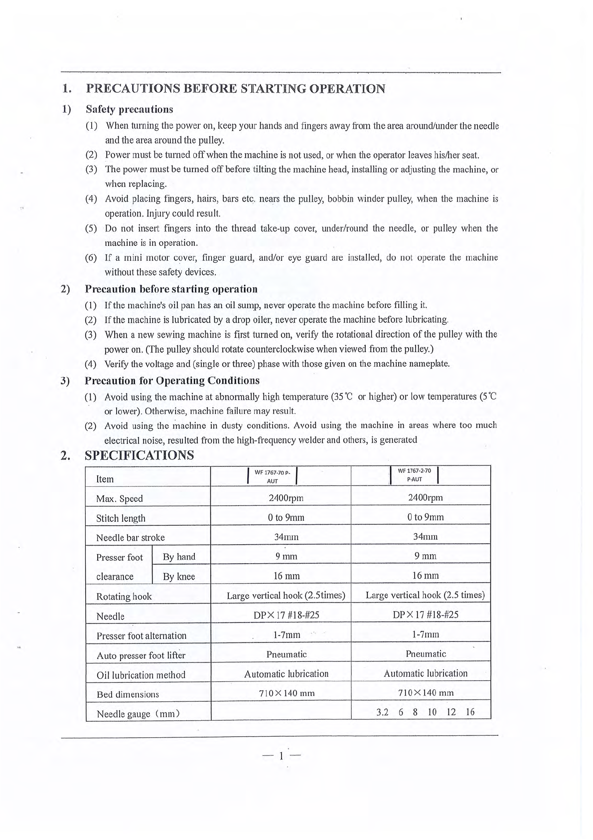
position .............................................................................................................. 3
5)
Lubrication
..................................................................................................................................................... 4
4.
HOW
TO
USE
THE MACHINE ........................................................................................................................ 5
I)
Threading················........................................................................................................................................ 5
2)
Adjust
ing
of
the
thread
regulator
.........................................................;.......
..
............................................ 5
3)
Adjusting
of
upper
thread
tension..........................,................................................................................. 5
4)
Winding
the
Io,ver
thread··
..····..................................................................................................................... 5
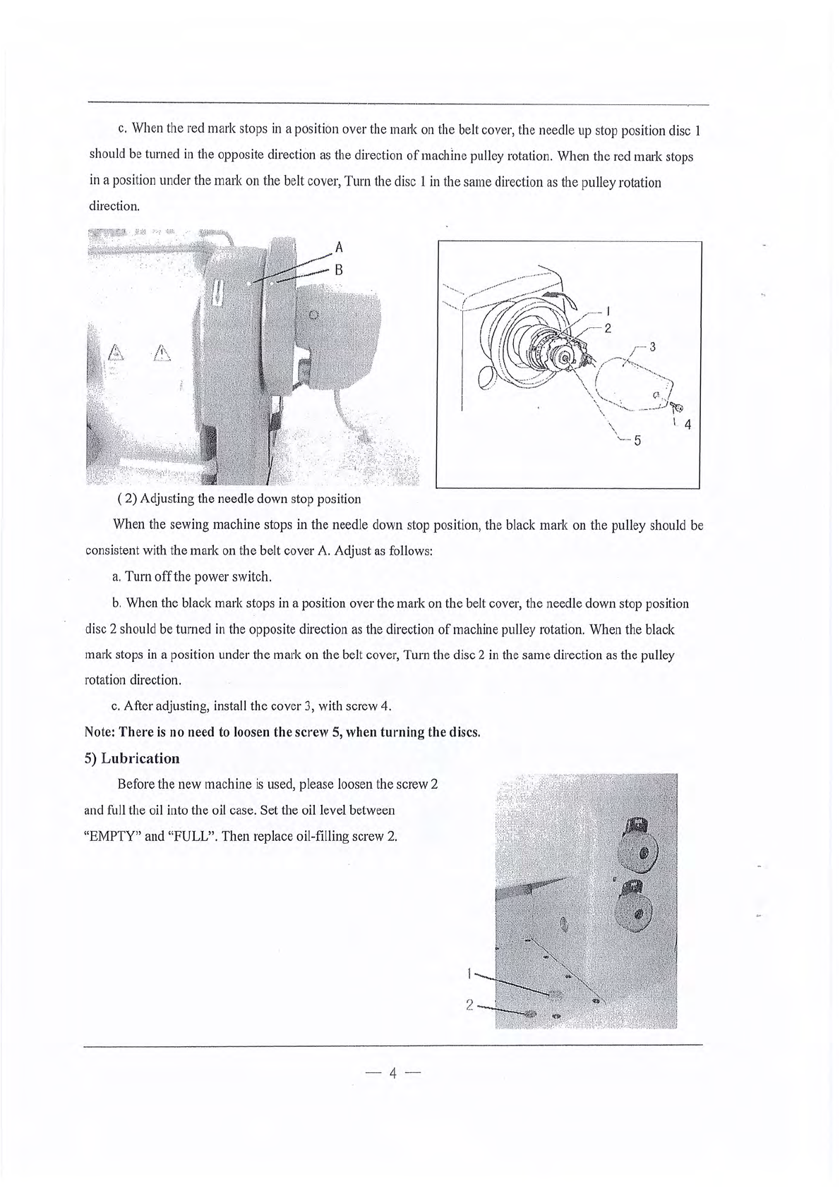
5)
Threading
the
lower
thrend
..........._.............................................................................................................. 6
6)
Adjusting
the
lower
-
thrend
tension·............................................................................................................ 6
7) l
nstnlling
the
needle.............:......................................................................................................................... 6
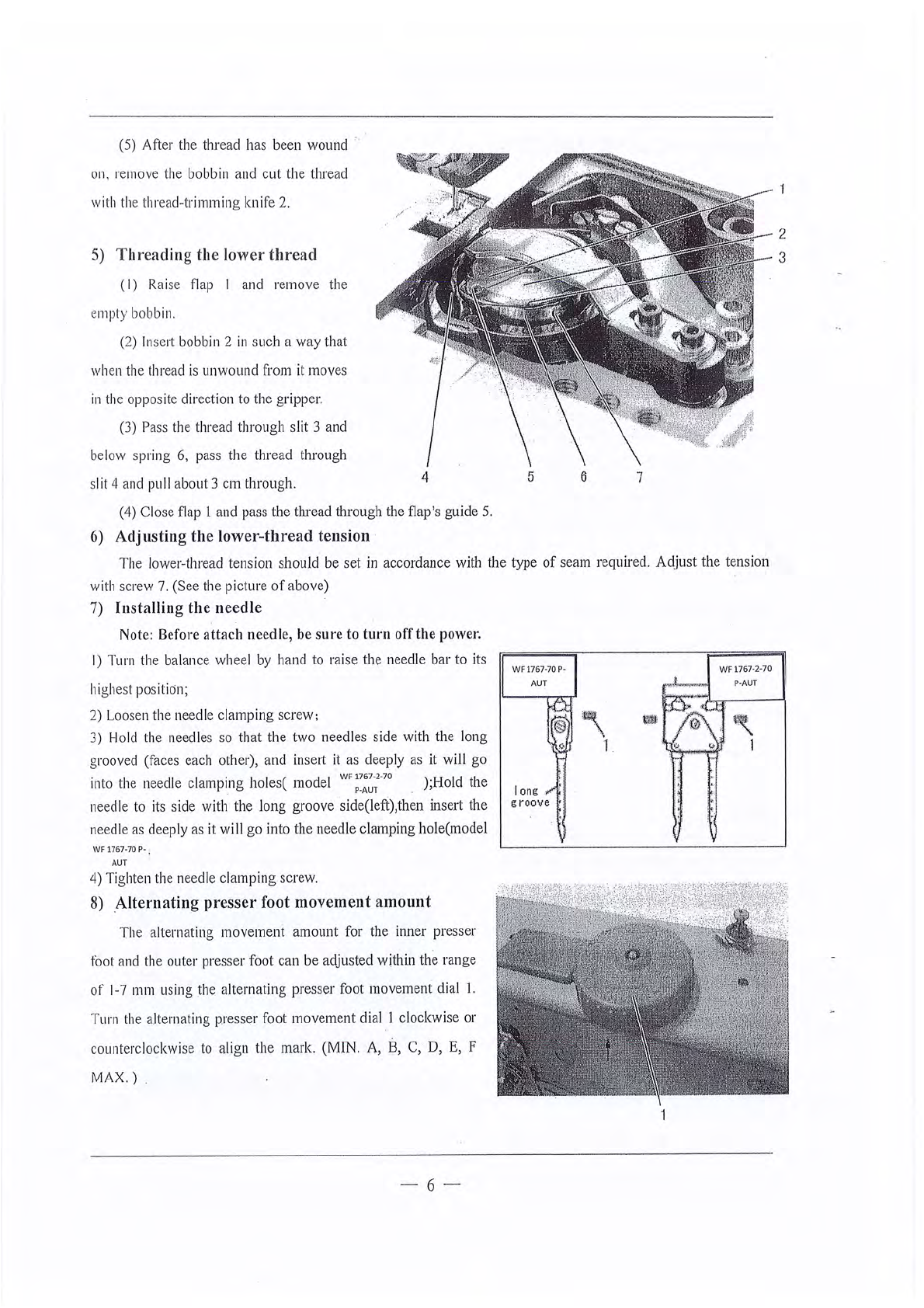
8)
Alternati
ng
presser
foot
1nove1nent
amount
.............................................................................................. 6
9)
Adjusting
the
presser
foot
pre
ssure..
........................................................................................................ 7
I
0)
Adjusting
the
stitch
l
ength
........................................................................................................................... 7
II)
Using
the
111nnual
switches........................................................................................................................... 7
12) Clenning······..·····.............................................................................................................................................. 8
13)
Lubrication
....................................
_.
......................................;...............................:......................................... 8
14)
Adjusting
the
tra
iling length
nfter
thread
trimming
................................................................................ 9
15)
Back
ta
cki
ng
................................................................................................................................................... 9
16) Adjus
ting
the
feed
dog
.................................................................................................................................. 9
17)
Adjusting
the
needl
e
bnr
height
.......................,........................................................................................... 9
.i
18)
Adjusting
th
e
gap
between
the
needle
nnd
the
rotary
hook
tip.........:.................................................. 10
1
9)
Adjusting
of
the
nee
dle
and
the
hook
timin
g........................................................................................... 10
20)
Hook
protection·
..·····..···................................................................................................................................
11
21)
Adjusting
the
needle a
nd
feed
mechani
sm timing...................................................................................
11
22)
Adjusting
the
opener
position.....................................................................................................................
11
23)
Adj
u
sting
the
presser
foot
heig
ht
.............................................................................................................. 12
24)
Adjus
ting
the
alternating
presser
foot
movement
amount
................................................................... 13
From the library of Superior Sewing Machine & Supply LLC - www.supsew.com