PPI QD User manual

INSTALLATION
Follow all instructions carefully. This is necessary to insure satisfactory performance
of both pulley and bushings. For units that have had the shaft installed at the factory,
retighten the capscrews with a torque wrench set at the proper value, as state in
Table 1.
1. Before installing the bushing, polish the following components:
• Surface of shaft.
• Bore of the bushing.
• Tapered inside diameter of the QD hub.
• Tapered outside diameter of the QD bushing.
Remove all burrs and foreign material; any particles left on the mating surfaces may
cause improper installation. Do not lubricate mating surfaces.
2. If pulley is to be keyed to shaft, make sure both shaft and bushing keyways are clean,
smooth, and free from burrs. Check key size with both shaft and bushing keyways.
Keys should be placed into the shaft keyways at this time. Pulley bushing keyways
require alignment of both shaft keyways for proper bushing to hub installation.
3. Place shaft into pulley and located in the desire position. Be careful not to damage the
bore of the hubs.
4. Carefully insert a wedge in the bushing split and tap lightly to expand the bushing. Use
caution as excessive expansion will cause the bushing to split. Slip bushings
onto shaft and into hubs with the drilled holes of the bushings lined up with the
threaded holes of the hub.
5. Place capscrews, including locking washers, into the unthreaded holes of each
bushing and hand tighten capscrews into the threaded holes of the hub.
6. Remove the wedge from the bushing split.
7. Tighten capscrews in each bushing slightly so that bushings are snug in hubs.
8. Using an accurate torque wrench and the recommended torque from Table 1, tighten
capscrews alternately and evenly in one bushing only. Use the numbered sequence
on the bushing flange capscrew heads in the Diagrams, starting with 1 first, 2 second,
etc., with all capscrews being used until the specified torque no longer turns the capscrews.
It is recommended to use a hammer and a heavy steel or bronze bar, drift on the face of the bushing, starting opposite the split. Avoid
drifting outside of the bolt circle. This will aid in seating of the shallow taper of a QD bushing.
Do not exceed recommended torque from Table 1 in attempt to pull bushing flange flush with hub face – there should be clearance when
tightened. If bushing flange is pulled flush with hub face while tightening capscrews to recommended torque, check for undersized shaft.
9. Repeat for the second bushing.
OPERATION & MAINTENANCE
QD®BUSHING
INSTALLATION INSTRUCTIONS
Diagram A
Table 1
Recommended QD Capscrew Torque
HUB # Diameter
(UNRC) Length Torque
(in lbs)
Torque
(N - M)
SH 31/4 1 1/4 108 12
SDS 31/4 1 1/4 108 12
SK 35/16 1 1/2 200 23
SF 33/8 2 360 41
E31/2 2 1/2 720 81
F39/16 2 1/2 900 102
JS 35/8 2 1/2 1,620 183
MS 43/4 3 2,700 305
NS 47/8 3 1/2 3,600 407
PS 4 1 3 1/2 5,400 610
WS 41 1/8 4 7,200 814
READ THESE INSTRUCTIONS CAREFULLY BEFORE STARTING INSTALLATION
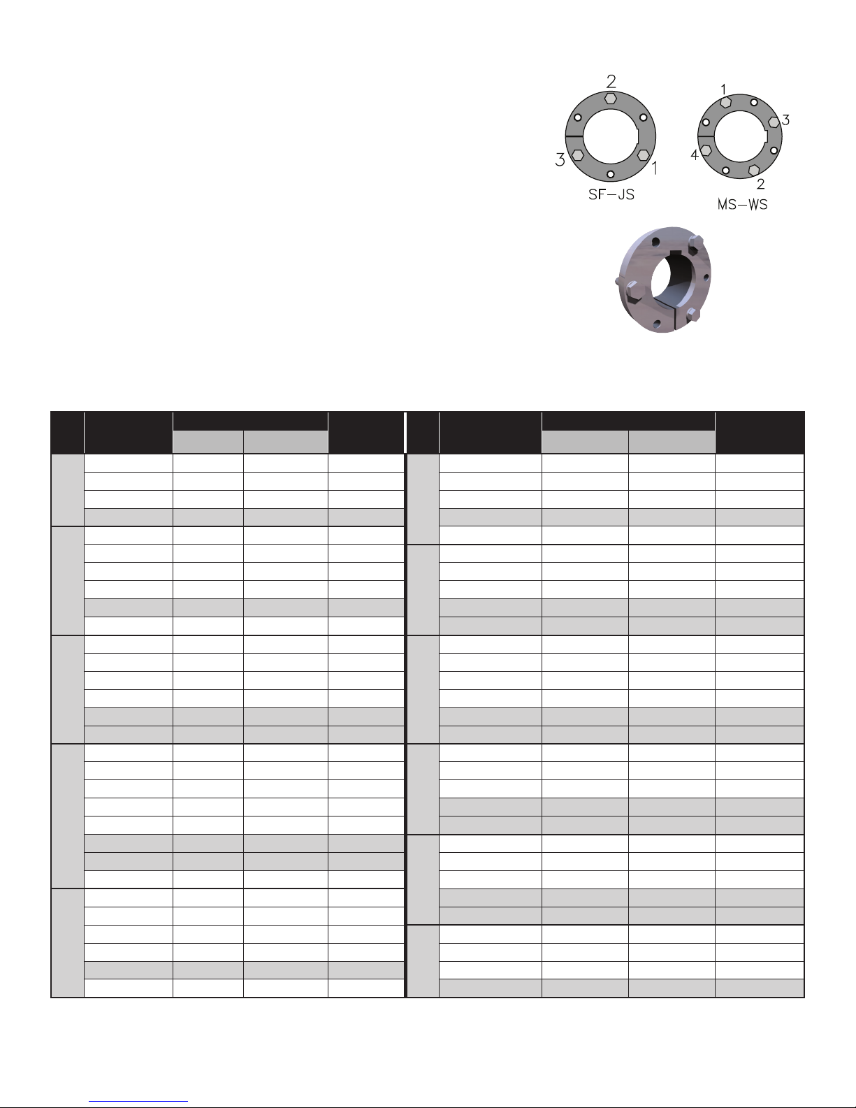
Diagram B Diagram C
MAINTENANCE
During the first month of operation, inspect bushings and capscrews for proper seating
at least once a week and re-torque as necessary. Thereafter inspect the bushings during
periodic shutdowns.
REMOVAL
1. Remove all capscrews.
2. Insert the capscrews into all threaded removal holes on bushings.
3. Tighten capscrews alternately and evenly in one bushing only until bushing
is loosened in hub. If bushing does not loosen immediately, tap on hub with
a soft hammer.
4. Remove bushing from the shaft. The use of a wedge carefully inserted in the split of
the flange will expand the bushing to make it easier to slide off the the shaft.
5. Remove the second bushing per steps 1-4.
QD®KEY SIZES
HUB Bore Range
Keyway
Keystock HUB Bore Range
Keyway
Keystock
Shaft Bushing Shaft Bushing
SH
5/8-7/8 3/16 x 3/32 3/16 x 3/32 3/16 x 3/16
F
1 15/16 - 2 1/4 1/2 x 1/4 1/2 x 1/4 1/2 x 1/2
15/16 - 1 1/4 1/4 x 1/8 1/4 x 1/8 1/4 x 1/4 2 5/16 - 2 3/4 5/8 x 5/16 5/8 x 5/16 5/8 x 5/8
1 5/16 - 1 3/8 5/16 x 5/32 5/16 x 5/32 5/16 x 5/16 2 13/16 - 3 1/4 3/4 x 3/8 3/4 x 3/8 3/4 x 3/4
1 7/16 - 1 5/8 3/8 x 3/16 3/8 x 1/16 3/8 x 1/4 3 5/16 - 3 3/4 7/8 x 7/16 7/8 x 3/16 7/8 x 5/8
SDS
5/8-7/8 3/16 x 3/32 3/16 x 3/32 3/16 x 3/16 3 13/16 - 4 NONE NONE NONE
15/16 - 1 1/4 1/4 x 1/8 1/4 x 1/8 1/4 x 1/4
JS
2 15/16 - 3 1/4 3/4 x 3/8 3/4 x 3/8 3/4 x 3/4
1 5/16 - 1 3/8 5/16 x 5/32 5/16 x 5/32 5/16 x 5/16 3 5/16 - 3 3/4 7/8 x 7/16 7/8 x 7/16 7/8 x 7/8
1 7/16 - 1 5/8 3/8 x 3/16 3/8 x 3/16 3/8 x 3/8 3 13/16 1 x 1/2 1 x 1/2 1 x 1
1 11/16 - 1 3/4 3/8 x 3/16 3/8 x 1/8 3/8 x 5/16 3 7/8 - 4 1 x 1/2 1 x 1/4 1 x 3/4
1 13/16 - 2 NONE NONE NONE 4 1/16 - 4 1/2 1 x 1/2 1 x 1/8 1 x 5/8
SK
15/16 - 1 1/4 1/4 x 1/8 1/4 x 1/8 1/4 x 1/4
MS
2 15/16 - 3 1/4 3/4 x 3/8 3/4 x 3/8 3/4 x 3/4
1 5/16 - 1 3/8 5/16 x 5/32 5/16 x 5/32 5/16 x 5/16 3 5/16 - 3 3/4 7/8 x 7/16 7/8 x 7/16 7/8 x 7/8
1 7/16 - 1 3/4 3/8 x 3/16 3/8 x 3/16 3/8 x 3/8 3 13/16 - 4 1/2 1 x 1/2 1 x 1/2 1 x 1
1 13/16 - 2 1/8 1/2 x 1/4 1/2 x 1/4 1/2 x 1/2 4 9/16 - 4 3/4 1 1/4 x 5/8 1 1/4 x 5/8 1 1/4 x 1 1/4
2 3/16 - 2 1/4 1/2 x 1/4 1/2 x 1/8 1/2 x 3/8 4 13/16 - 5 1/4 1 1/4 x 5/8 1 1/4 x 3/8 1 1/4 x 1
2 5/16 - 2 1/2 5/8 x 5/16 5/8 x 1/16 5/8 x 3/8 5 5/16 - 5 1/2 1 1/4 x 5/8 1 1/4 x 1/4 1 1/4 x 7/8
SF
15/16 - 1 1/4 1/4 x 1/8 1/4 x 1/8 1/4 x 1/4
NS
3 7/16 - 3 3/4 7/8 x 7/16 7/8 x 7/16 7/8 x 7/8
1 5/16 - 1 3/8 5/16 x 5/32 5/16 x 5/32 5/16 x 5/16 3 13/16 - 4 1/2 1 x 1/2 1 x 1/2 1 x 1
1 7/16 - 1 3/4 3/8 x 3/16 3/8 x 3/16 3/8 x 3/8 4 9/16 - 5 1/4 1 1/4 x 5/8 1 1/4 x 5/8 1 1/4 x 1 1/4
1 13/16 - 2 1/4 1/2 x 1/4 1/2 x 1/4 1/2 x 1/2 5 5/16 - 5 1/2 1 1/4 x 5/8 1 1/4 x 3/8 1 1/4 x 1
2 5/16 5/8 x 5/16 5/8 x 5/16 5/8 x 5/8 5 9/16 - 6 1 1/2 x 3/4 1 1/2 x 1/4 1 1/2 x 1
2 3/8 - 2 1/2 5/8 x 5/16 5/8 x 3/16 5/8 x 1/2
PS
3 15/16 - 4 1/2 1 x 1/2 1 x 1/2 1 x 1
2 9/16 - 2 3/4 5/8 x 5/16 5/8 x 1/16 5/8 x 3/8 4 9/16 - 5 1/2 1 1/4 x 5/8 1 1/4 x 5/8 1 1/4 x 1 1/4
2 13/16 - 2 15/16 NONE NONE NONE 5 9/16 - 6 1/4 1 1/2 x 3/4 1 1/2 x 3/4 1 1/2 x 1 1/2
E
1 7/16 - 1 3/4 3/8 x 3/16 3/8 x 3/16 3/8 x 3/8 6 5/16-6 1/2 1 1/2 x 3/4 1 1/2 x 1/2 1 1/2 x 1 1/4
1 13/16 - 2 1/4 1/2 x 1/4 1/2 x 1/4 1/2 x 1/2 6 9/16-7 1 3/4 x 3/4 1 3/4 x 1/4 1 3/4 x 1
2 5/16 - 2 3/4 5/8 x 5/16 5/8 x 5/16 5/8 x 5/8
WS
5 15/16 - 6 1/2 1 1/2 x 3/4 1 1/2 x 3/4 1 1/2 x 1 1/2
2 13/16 - 2 7/8 3/4 x 3/8 3/4 x 3/8 3/4 x 3/4 6 9/16 - 7 1/2 1 3/4 x 3/4 1 3/4 x 3/4 1 3/4 x 1 1/2
2 15/16 - 3 1/4 3/4 x 3/8 3/4 x 1/8 3/4 x 1/2 7 9/16 - 8 1/8 2 x 3/4 2 x 3/4 2 x 1 1/2
3 5/16 - 3 1/2 NONE NONE NONE 8 3/16 - 8 1/2 2 x 3/4 2 x 1/4 2 x 1
Keys are provided for shaded cells only, (non-standard key sizes)
Unshaded keysizes are FULL Depth Keys

QD®METRIC KEY SIZES
METRIC DIMENSIONS (mm) DIMENSIONS CONVERTED TO ENGLISH UNITS (in)
HUB Bore Shaft Bushing Keystock Length HUB Bore Key Width Key Height Length
SF
20 6 x 3.5 6 x 2.8 6 x 6
53 SF
0.787 0.236 0.236
2 1/16
25 - 30 8 x 4 8 x 3.3 8 x 7 0.984 - 1.181 0.315 0.276
35 10 x 5 10 x 3.3 10 x 8 1.378 0.394 0.315
40 12 x 5 12 x 3.3 12 x 8 1.575 0.472 0.315
45 - 50 14 x 5.5 14 x 3.8 14 x 9 1.772 - 1.969 0.551 0.354
55 16 x 6 16 x 4.3 16 x 10 2.165 0.63 0.394
60 18 x 7 18 x 4.4 18 x 11 2.362 0.709 0.433
65 - 75 None None None 2.559 - 2.953 None None
E
20 6 x 3.5 6 x 2.8 6 x 6
70 E
0.787 0.236 0.236
2 3/4
25 - 30 8 x 4 8 x 3.3 8 x 7 0.984 - 1.181 0.315 0.276
35 10 x 5 10 x 3.3 10 x 8 1.378 0.394 0.315
40 12 x 5 12 x 3.3 12 x 8 1.575 0.472 0.315
45 - 50 14 x 5.5 14 x 3.8 14 x 9 1.772 - 1.969 0.551 0.354
55 16 x 6 16 x 4.3 16 x 10 2.165 0.63 0.394
60 - 65 18 x 7 18 x 4.4 18 x 11 2.362 - 2.559 0.709 0.433
70 20 x 7.5 20 x 4.9 20 x 12 2.756 0.787 0.472
75 -90 None None None 2.953 - 3.543 None None
F
25 - 30 8 x 4 8 x 3.3 8 x 7
95 F
0.984 - 1.181 0.315 0.276
3 3/4
35 10 x 5 10 x 3.3 10 x 8 1.378 0.394 0.315
40 12 x 5 12 x 3.3 12 x 8 1.575 0.472 0.315
45 - 50 14 x 5.5 14 x 3.8 14 x 9 1.772 - 1.969 0.551 0.354
55 16 x 6 16 x 4.3 16 x 10 2.165 0.63 0.394
60 - 65 18 x 7 18 x 4.4 18 x 11 2.362 - 2.559 0.709 0.433
70 - 75 20 x 7.5 20 x 4.9 20 x 12 2.756 - 2.953 0.787 0.472
80 - 85 22 x 9 22 x 5.4 22 x 14 3.150 - 3.346 0.866 0.551
90 25 x 9 25 x 5.4 25 x 14 3.543 0.984 0.551
95 - 100 None None None 3.740 - 3.937 None None
JS
35 10 x 5 10 x 3.3 10 x 8
85 JS
1.378 0.394 0.315
3 3/8
40 12 x 5 12 x 3.3 12 x 8 1.575 0.472 0.315
45 - 50 14 x 5.5 14 x 3.8 14 x 9 1.772 - 1.969 0.551 0.354
55 16 x 6 16 x 4.3 16 x 10 2.165 0.63 0.394
60 - 65 18 x 7 18 x 4.4 18 x 11 2.362 - 2.559 0.709 0.433
70 - 75 20 x 7.5 20 x 4.9 20 x 12 2.756 - 2.953 0.787 0.472
80 - 85 22 x 9 22 x 5.4 22 x 14 3.150 - 3.346 0.866 0.551
90 - 95 25 x 9 25 x 5.4 25 x 14 3.543 - 3.740 0.984 0.551
100 - 110 28 x 10 28 x 6.4 28 x 16 3.937 - 4.331 1.102 0.63
MS
65 18 x 7 18 x 4.4 18 x 11
122 MS
2.559 0.709 0.433
4 13/16
70 - 75 20 x 7.5 20 x 4.9 20 x 12 2.756 - 2.953 0.787 0.472
80 - 85 22 x 9 22 x 5.4 22 x 14 3.150 - 3.346 0.866 0.551
90 - 95 25 x 9 25 x 5.4 25 x 14 3.543 - 3.740 0.984 0.551
100 - 110 28 x 10 28 x 6.4 28 x 16 3.937 - 4.331 1.102 0.63
115 -130 32 x 11 32 x 7.4 32 x 18 4.528 - 5.118 1.26 0.709
NS
100 - 110 28 x 10 28 x 6.4 28 x 16
152 NS
3.937 - 4.331 1.102 0.63
6115 -130 32 x 11 32 x 7.4 32 x 18 4.528 - 5.118 1.26 0.709
135-140 36 x 12 36 x 8.4 36 x 20 5.312 - 5.512 1.417 0.787
PS 150 36 x 12 36 x 8.4 36 x 20 165 PS 5.906 1.417 0.787 6 1/2
160 40 x 13 40 x 9.4 40 x 22 6.299 1.575 0.866
WS 170 40 x 13 40 x 9.4 40 x 22 184 WS 6.693 1.575 0.866 7 1/4
180 45 x 15 45 x 10.4 45 x 25 7.087 1.772 0.984
OM 010 Contact your sales representative for more information 03/14
©2014 | Precision Pulley & Idler | All Rights Reserved
CORpORATe OffICe • P.O. Box 287 • Pella, IA 50219
800.247.1228 • 641.628.3115 • 641.628.3658 FAX


