Skutt KilnMaster KM1027 Installation guide

6441 SE Johnson Creek Blvd., Portland, OR 97206 Phone (503) 774-6000 Fax (503) 774-7833
www.skutt.com
TAB TEXT HERE TAB TEXT HERE TAB TEXT HERE TAB TEXT HERE
SERVICE TRAINING MANUAL
14.1 REV 11/19/04
REPAIRS
(continued)
KilnMaster Relay Replacement
FOR MODELS: KM1027 / KM1227 1-PHASE 208/240 VOLT
This relay replacement kit is intended to replace three relays and all the necessary relay wir-
ing in your kiln. It is absolutely necessary to install the entire kit including all relays and wiring
for proper performance. Do not re-use any of the original black wiring.
Your new relay replacement kit consists of the following items:
1. Three relays with all of the necessary harness and control wires attached
2. One relay adapter plate.
The tool necessary to install the relay replacement kit is a #2 Phillips screwdriver
STEP-BY-STEP INSTRUCTIONS:
Before beginning the actual replacement, it is strongly recommended to read through these
instructions to familiarize yourself with the following procedures.
RELAY AND WIRING REMOVAL
1. Unplug your kiln. Remove your control box from the kiln. Place
the control box, face down on a flat surface. Protect the touchpad
of your control box with a soft cloth or towel.
2. Remove the fiberglass lined heat baffle by removing the six sheet
metal screws holding it in place. Carefully lift the heat baffle out
of the control box, taking care not to stretch the attached wires on
the underside.
3. Using the Phillips screwdriver, remove the six black wires at-
tached to the heat baffle terminal strip. Save your screws. If you
want to get the heat baffle entirely out of the way, remove the
remaining red and yellow thermocouple wires.
4. Begin removal of the three old relays from the control box by
removing the six sheet metal screws holding the relays in place.
Save your screws. ALL wires, both black and red, connected to
the relays will be removed. With the relays loosened, remove the
two large screws on the terminal block holding the black relay
wiring in place. The wires at this point should be crimped into
two large silver connectors that also will contain one red wire
each. Follow each red wire and remove the push-on connectors
from the fuse holder and the transformer bottom tab. Use a gentle
side to side rocking and pulling motion to remove these connec-
tors. Be especially careful when removing the connector from
the transformer to avoid damaging it. Remove the red connector
from the top-center transformer tab also. Remove the top red
wire connected to the circuit board labeled output 2. Remove the
double red wire on the circuit board labeled center tap. Carefully
pull the relays and all attached wires out of the control box.
5. Refer to photo #1 to ensure that all of the relays and proper wiring have been re-
moved.
PHOTO #1

TAB TEXT HERETAB TEXT HERE TAB TEXT HERE TAB TEXT HERE TAB TEXT HERE
REPAIRS
SERVICE TRAINING MANUAL
14.1 REV 11/19/04
RELAY REPLACEMENT CONTINUED
Page 2
RELAY INSTALLATION
1. Inspect the orientation of the new relays, wiring and metal
adapter plate in its shipping cardboard. The relays will be
installed in the control box with the same orientation. Remove
the new relays, wiring and metal adapter place from its packing
material. Take care to keep the orientation of the new relays as
packed to avoid twisting the wires. Locate the metal adapter
plate; it will be installed first.
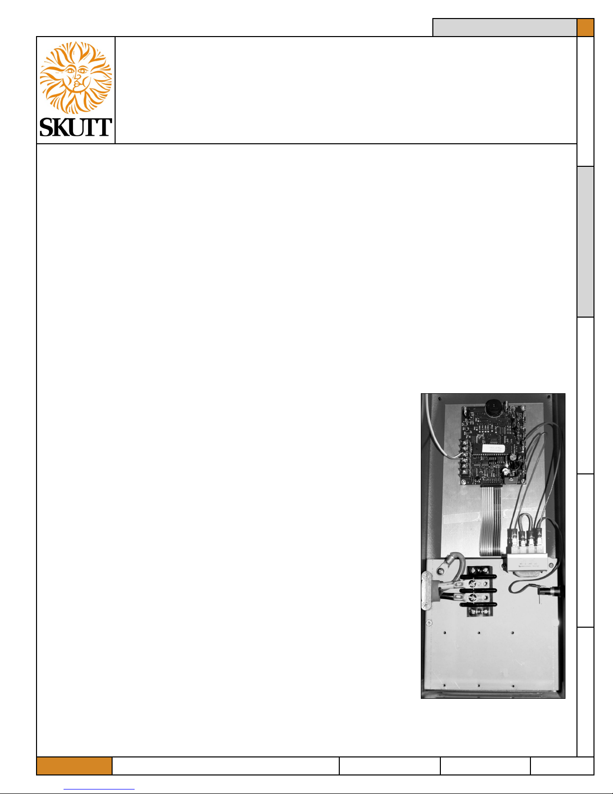
2. Install the metal relay adapter plate in the control box using 3 of
the old relay screws. The silver colored spacers on the adapter
plate should be placed directly against the metal chassis and
screwed down lightly. Use the bottom set of existing holes in the
metal chassis for mounting the adapter plate. Refer to photo #2
for the proper orientation of the metal adapter plate.
3. Place the 3 new relays and wiring harnesses in place on the
metal chasses. Slide the bottom lip of each relay in its proper place. The plastic lip of
the relays should slide underneath the top notched portion of the metal relay adapter
plate.
4. Using the remaining 3 old relay screws, fasten down the remaining lips of the new
relays using the existing holes in the metal chassis. Lightly tighten down all six screws
holding the relays in place. Do not overtighten the screws as they may strip out.
5. Locate the two large silver ring tongue connectors that contain 3 white wires and one
small red wire each and fasten to the terminal block securely. It makes no difference
if the ring tongue connectors are switched in position on the terminal block. Tighten
these screws VERY tight.
6. Locate the two small red wires mentioned above in step #5. Plug one red wire into the
vacant bottom tab of the transformer and the other red wire into the fuse holder.
7. Locate the two long red wires attached to the black relays. One wire will have a double
end. Plug the wire with the double lead into the circuit board in the position labeled
center tap. Plug the loose end of this wire into the top center tab of the transformer.
Plug the other single long red wire into the circuit board on the tab labeled output 2.
8. Find the six, white, ten inch long wires attached to the relays. Attach these six wires
to the heat baffle terminal strip using the old screws. Attach wire #1 (wires designa-
tions are labled on each relay) to position #1 on the terminal strip. Ensure that these
connectors are lined up nicely and securely tightened. Refer to the numbered strip on
the other side of the heat baffle for proper wire position. Reconnect the red and yellow
thermocouple wire if necessary. Make sure the red thermocouple wire is connected to
the negative position of the terminal strip. This would be the end (or bottom) connec-
tor on the terminal strip. It is labeled “-” on the other side.
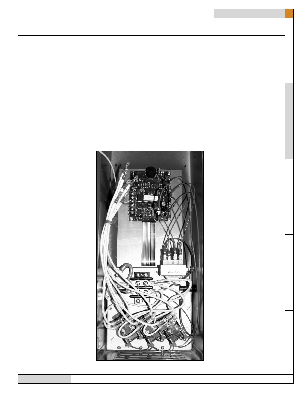
9. All of the wiring should be connected now. Check all wiring for any loose ends or
unattached connectors. Refer to the photo #3, finished wiring, if necessary to determine
proper connection points. Ensure that all wiring is neatly routed around components
such as the transformer. Reroute the wiring as necessary to eliminate kinks or pinch

TAB TEXT HERETAB TEXT HERE TAB TEXT HERE TAB TEXT HERE TAB TEXT HERE
REPAIRS
SERVICE TRAINING MANUAL
14.1 REV 11/19/04
RELAY REPLACEMENT CONTINUED
points.
10. Reinstall the fiberglass lined heat baffle in place using the six sheet metal screws.
When placing the heat baffle in place, ensure that no wiring is pinched or caught in the
control box.
11. Reinstall the control box on your kiln. Ensure that all the white feeder wires are con-
nected, that none of the tabs are loose and that the thermocouple push on connectors
are connected to the proper polarity (red is negative “-”). Close the control box and
secure using the six sheet metal screws.
Your installation should be complete!
12. An empty test firing of your kiln is strongly recommended before firing any valuable
Page 3
PHOTO #3
This manual suits for next models
1
Table of contents
Other Skutt Other manuals
Popular Other manuals by other brands

Haier
Haier CXW-219-D68VQ manual

Meinberg
Meinberg LANTIME M300/GPS/2LNE/RPS Technical reference

AXXIOM Manufacturing, Inc.
AXXIOM Manufacturing, Inc. SCHMIDT 0.9 Cu. Ft Operation and maintenance manual

Downee
Downee Sprint Gate Solar Series Install manual

EMG
EMG 81-TW-X Installation information

AMX
AMX AXC-232 Specifications