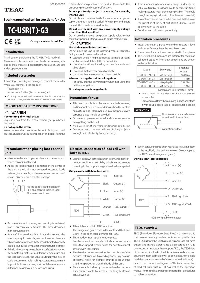
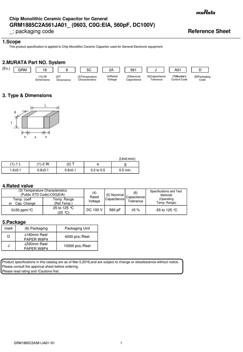
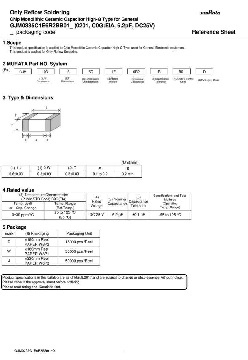
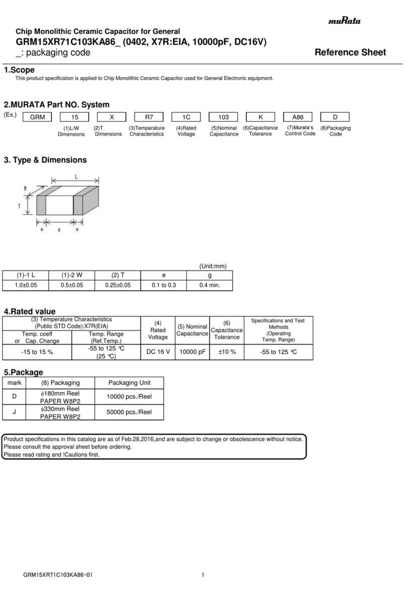
PR electronics 5202B User manual

16 17
PULSE ISOLATOR
PRecon 5202B
Contents
Warnings ............................................................................ 18
Safety instructions .............................................................. 19
EC Declaration of Conformity ............................................ 21
How to dismantle SYSTEM 5000 ....................................... 22
Application ......................................................................... 23
Technical characteristics .................................................... 23
Mounting / installation ........................................................ 23
Applications ........................................................................ 24
Order .................................................................................. 25
Electrical specifications ...................................................... 25
Jumper programming ......................................................... 28
Function description........................................................... 29
Block diagram 5202B1 and 5202B2 .................................. 30
Block diagram 5202B4 ....................................................... 31
Connections ....................................................................... 32
Appendix:
UL Control Drawing No. 5202QU01................................... 65
31 32 33
43
41 42
Rp
Rs
53
51 52
Rp
Rs
43
41 42
+
-
53
51 52
+
-
43
41 42
53
51 52
53
51 52
Rp
43
41 42
Rp
11 12 13 11 12 13
+
-
Rp = 15 k
Rs = 750
Ω
Ω
Rp = 15 k
Rs = 750
Ω
Ω
11 12 14
13 11 12 14
13
21 22 24
23 21 22 24
23
23
21 22
+
-
23
21 22
Tilslutninger:
Forsyning:
Udgange:
5202B1 og -B2:
Kanal 1Kanal 2 Kanal 2
Indgange:
Kanal 1
Kontakt
Relæ
5202B4:
2 x Relæ N.O. 2 x Relæ N.C.
2 x Relæ N.C.2 x Relæ N.O.
Åben kollektor,
NPN
Åben kollektor,
NPN
NAMUR-føler Kontakt, kabelfejl Kontakt, kabelfejl
Kontakt
Relæ
NAMUR-føler Kontakt, kabelfejl Kontakt, kabelfejl
monteres på
kontakt
monteres på
kontakt

18 19
Symbol identification:
Triangle with an exclamation mark: Warning / demand. Potentially
le thal situations.
The CE mark proves the compliance of the module with the essential
requirements of the directives.
The double insulation symbol shows that the module is protected by
double or reinforced insulation.
Ex modules have been approved acc. to the ATEX directive for use in
connection with installations in explosive areas.
SAFETY INSTRUCTIONS
DEFINITIONS:
Hazardous voltages have been defined as the ranges: 75...1500 Volt DC, and
50...1000 Volt AC.
Technicians are qualified persons educated or trained to mount, operate, and
also troubleshoot technically correct and in accordance with safety regulations.
Operators, being familiar with the contents of this manual, adjust and operate
the knobs or potentiometers during normal operation.
RECEIPT AND UNPACKING:
Unpack the module without damaging it and make sure that the manual always
follows the module and is always available. The packing should always follow
the module until this has been permanently mounted.
Check at the receipt of the module whether the type corresponds to the one
ordered.
ENVIRONMENT:
Avoid direct sunlight, dust, high temperatures, mechanical vibrations and shock,
as well as rain and heavy moisture. If necessary, heating in excess of the stated
limits for ambient temperatures should be avoided by way of ventilation.
All modules fall under Installation Category II, Pollution Degree 1, and Insulation
Class II.
WARNING
This module is designed for connection to hazardous electric
voltages. Ignoring this warning can result in severe personal
injury or mechanical damage.
To avoid the risk of electric shock and fire, the safety instructions
of this manual must be observed and the guidelines followed.
The specifications must not be exceeded, and the module must
only be applied as described in the following.
Prior to the commissioning of the module, this manual must be
examined carefully.
Only qualified personnel (technicians) should install this module.
If the equipment is used in a manner not specified by the
manufacturer, the protection provided by the equipment may be
impaired.
WARNING
Until the module is fixed, do not connect hazardous voltages to
the module. The following operations should only be carried out
on a disconnected module and under ESD-safe conditions:
Dismantlement of the module for setting of dipswitches and
jumpers.
General mounting, connection and disconnection of wires.
Troubleshooting the module.
Repair of the module and replacement of circuit breakers
must be done by PR electronics A/S only.
GENERAL
HAZARD-
OUS
VOLTAGE
WARNING
5202B4:
To keep the safety distances, one relay must not be connected
to hazardous voltage at the same time as the other relay on the
same channel is connected to non-hazardous voltage.
INSTAL-
LATION

20 21
EC DECLARATION OF CONFORMITY
As manufacturer
PR electronics A/S
Lerbakken 10
DK-8410 Rønde
hereby declares that the following product:
Type: 5202B
Name: Pulse isolator
is in conformity with the following directives and
standards:
The EMC Directive 2004/108/EC and later amendments
EN 61326-1 : 2006
For specification of the acceptable EMC performance level, refer to the
electrical specifications for the module.
The Low Voltage Directive 2006/95/EC and later amendments
EN 61010-1 : 2001
The ATEX Directive 94/9/EC and later amendments
EN 50014 : 1997 E incl. A1+A2, EN 50020 : 2002 E and
EN 50281-1-1 : 1998 incl. A1
ATEX certificate: DEMKO 99ATEX127186
No changes are required to enable compliance with the replacement standards:
EN 60079-0 : 2006 and EN 60079-11 : 2007
EN 61241-1 : 2006 and EN 61241-11 : 2007
Notified body
UL International Demko A/S (0539)
Lyskaer 8
P.O. Box 514
DK-2730 Herlev
Rønde, 21 April 2010 Kim Rasmussen
Manufacturer’s signature
MOUNTING:
Only technicians who are familiar with the technical terms, warnings, and
in struc tions in the manual and who are able to follow these should connect the
module.
Should there be any doubt as to the correct handling of the module, please
contact your local distributor or, alternatively,
PR electronics A/S, Lerbakken 10, 8410 Rønde, Danmark tlf: +45 86 37 26 77.
Mounting and connection of the module should comply with national legislation
for mounting of electric materials, i.e. wire cross section, protective fuse, and
location. Descriptions of input / output and supply connections are shown in
the block diagram and on the side label.
The following apply to fixed hazardous voltages-connected modules:
The max. size of the protective fuse is 10 A and, together with a
power switch, it should be easily accessible and close to the module.
The power switch should be marked with a label indicating that it will
switch off the voltage to the module.
Year of manufacture can be taken from the first two digits in the serial number.
CALIBRATION AND ADjUSTMENT:
During calibration and adjustment, the measuring and connection of external
voltages must be carried out according to the specifications of this manual. The
technician must use tools and instruments that are safe to use.
NORMAL OPERATION:
Operators are only allowed to adjust and operate modules that are safely fixed
in panels, etc., thus avoiding the danger of personal injury and damage. This
means there is no electrical shock hazard, and the module is easily accessible.
CLEANING:
When disconnected, the module may be cleaned with a cloth moistened with
distilled water.
LIABILITY:
To the extent the instructions in this manual are not strictly observed, the
customer cannot advance a demand against PR electronics A/S that would
otherwise exist according to the concluded sales agreement.

22 23
PULSE ISOLATOR
PRecon 5202B
• 2 channels - 2 or 4 outputs
• 5-port 3.75 kVAC galvanic isolation
• Dual output
• Cable error detection
• Universal AC or DC supply
Application:
• Pulse isolator with safety barrier for the supply of NAMUR sensors installed in
the hazardous area.
• Pulse isolator with safety barrier for the detec tion of mechanical contacts
installed in the hazardous area.
• One input signal can be used on two separate outputs.
• A cable error alarm can be detected on a sep arate output.
Technical characteristics:
• PR5202B1 and 5202B2 have relays with change-over contacts or open NPN
collectors available in the safe area.
• PR5202B4 has 4 SPST relays, which are activated simultaneously two and
two, available in the safe area. Each relay can be programmed to the function
N.O. or N.C.
• Inputs, outputs, and supply are floating and galvanically separated.
• The 5202B is designed according to strict safety requirements and is thus
suit able for application in SIL 2 installations.
Mounting / installation:
• Mounted vertically or horizontally on a DIN rail. Up to 84 channels per metre
can be mounted.
HOW TO DISMANTLE SYSTEM 5000
First, remember to demount the connectors with hazardous voltages.
Picture 1:
By lifting the bottom lock, the module
is detached from the DIN rail.
Picture 2:
Then, by lifting the upper lock
and pulling the front plate
simultaneously, the PCB is removed.
Switches and jumpers can now be
adjusted.

24 25
Electrical specifications:
Specifications range:
-20 to +60°C
Common specifications:
Supply voltage universal ............................. 21.6...253 VAC
50...60 Hz
19.2...300 VDC
Internal consumption, 5202B1 and 5202B2 . ≤ 1.5 W (2 channels)
Max. consumption, 5202B1 and 5202B2 ... ≤ 1.5 W (2 channels)
Internal consumption, 5202B4 ..................... ≤ 2.0 W (2 channels)
Max. consumption, 5202B4 ........................ ≤ 2.0 W (2 channels)
Fuse ............................................................. 400 mA T / 250 VAC
Isolation voltage, test / operation ............... 3.75 kVAC / 250 VAC
Calibration temperature............................... 20...28°C
Auxiliary voltage:
NAMUR supply ............................................ 8 VDC / 8 mA
Max. wire size .............................................. 1 x 2.5 mm2 stranded wire
Screw terminal torsion ................................ 0.5 Nm
Relative humidity ......................................... < 95% RH (non-cond.)
Dimensions (HxWxD) ................................... 109 x 23.5 x 130 mm
DIN rail type ................................................. DIN 46277
Protection degree ........................................ IP20
Weight ......................................................... 230 g
EMC immunity influence ..................................... < ±0.5%
Extended EMC immunity:
NAMUR NE 21, A criterion, burst ....................... < ±1%
Rp
Rs
Supply
Supply
Supply
Supply
NAMUR sensors
1 NAMUR sensor
Contact with
cable error detection
Contact
Outputs
Output
Outputs
Cable
error
Signal
2 outputs

26 27
GOST R approval:
VNIIM & VNIIFTRI, Cert. no. ........................ See www.prelectronics.com
Observed authority requirements: Standard:
EMC 2004/108/EC ...................................... EN 61326-1
LVD 2006/95/EC .......................................... EN 61010-1
PELV/SELV ................................................... IEC 364-4-41 and EN 60742
ATEX 94/9/EC .............................................. EN 50014, EN 50020 and
EN 50281-1-1
UL ................................................................ UL 913, UL 508
Inputs:
Sensor types:
NAMUR acc. to ....................................... EN 60947-5-6
Mechanical contact
Frequency range ......................................... 0...5 kHz
Pulse length ................................................. > 0.1 ms
Input resistance ........................................... 1 kΩ
Trig level, signal ........................................... < 1.2 mA, > 2.1 mA
Trig level, cable error ................................... < 0.1 mA, > 6.5 mA
Outputs:
Relay outputs:
Max. frequency ............................................ 20 Hz
Max. voltage ................................................ 250 VRMS
Max. current ................................................ 2 A / AC
Max. AC power ........................................... 100 VA
Max. load at 24 VDC ................................... 1 A
Open NPN collector outputs:
Max. frequency ............................................ 5 kHz
Pulse length ................................................. > 0.1 ms
Load, max. current / voltage ....................... 80 mA / 30 VDC
Voltage drop at 25 mA / 80 mA .................. < 0.75 VDC / < 2.5 VDC
EEx / I.S. approvals:
DEMKO 99ATEX127186 .............................. II (1) GD
[EEx ia] IIC
Applicable for zone ..................................... 0, 1, 2, 20, 21 or 22
Ex / I.S. data:
Terminal 41...43, (51...53)
Um ............................................................... : 250 V
Uo ................................................................ : 10.6 VDC
Io. ................................................................. : 13.8 mADC
Po ................................................................ : 38 mW
Lo ................................................................. : 160 mH
Co ................................................................ : 1.9 µF
UL ................................................................ IS, CL. I, Div. 1, Group A, B, C, D
IS, CL. I, zone 0 and 1, Group IIC
IS, CL. II, Div. 1, Group E, F, G
UL Control Drawing No. .......................... 5202QU01 (see appendix)

28 29
Function description:
Examples of connections on block diagram (1)...(4)
(1) NAMUR sensor with cable error detection in case of cable disconnection or
short-circuit.
(2) Mechanical contact with cable error detection in case of cable disconnection
or short-circuit, when Rs and Rp are mounted on the contact.
(3) Mechanical contact with cable error detection in case of cable disconnection,
when Rp is mounted on the contact.
(4) Mechanical contact without cable error detection.
jumper programming:
• When a channel 1 signal or cable errors are transmitted to channel 2, JP 22
must be in position 2-3, and JP 23 must be in position 1-2.
• Signal transmission to channel 2: If the channel 1 signal is inverted (JP11 in
position 2-3), the channel 2 signal will also be inverted. In this case, the
inversion on channel 2 can be reversed by inverting the channel 2 signal
(JP21 in position 2-3).
• When channel 2 is used individually, input 2 is activated by JP 23 in position
2-3.

30 31
BLOCK DIAGRAM: 5202B4BLOCK DIAGRAM: 5202B1 AND 5202B2

32 33
ISOLATEUR D’IMPULSIONS
PRecon 5202B
Sommaire
Avertissements ................................................................... 34
Consignes de sécurité ....................................................... 35
Déclaration de conformité CE ............................................ 37
Démontage du SYSTEME 5000 ......................................... 38
Application ......................................................................... 39
Caractéristiques techniques............................................... 39
Montage / installation ......................................................... 39
Applications ........................................................................ 40
Référence de commande ................................................... 41
Spécifications électriques .................................................. 41
Programmation des cavaliers ............................................. 44
Déscription des fonctions .................................................. 45
Schéma de principe 5202B1 et 5202B2 ............................ 46
Schéma de principe 5202B4 .............................................. 47
Connexions ........................................................................ 48
Appendice :
UL Control Drawing No. 5202QU01................................... 65
31 32 33
43
41 42
Rp
Rs
53
51 52
Rp
Rs
43
41 42
+
-
53
51 52
+
-
43
41 42
53
51 52
53
51 52
Rp
43
41 42
Rp
11 12 13 11 12 13
+
-
Rp = 15 k
Rs = 750
Ω
Ω
Rp = 15 k
Rs = 750
Ω
Ω
11 12 14
13 11 12 14
13
21 22 24
23 21 22 24
23
23
21 22
+
-
23
21 22
Connections:
Supply:
Outputs:
Channel 1Channel 2 Channel 2
Inputs:
Channel 1
Contact
Relay Open
collector, NPN
Open
collector, NPN
NAMUR sensor Contact, cable error Contact, cable error
Contact
Relay
NAMUR sensor Contact, cable error Contact, cable error
to be mounted
on contact
to be mounted
on contact
5202B4:
2 x Relay N.O. 2 x Relay N.C.
2 x Relay N.C.2 x Relay N.O.
5202B1 and 5202B2:
Table of contents
Other PR electronics Industrial Electrical manuals
PR electronics
PR electronics 9202 Series User manual
PR electronics
PR electronics 9203 Series User manual
PR electronics
PR electronics 9202 Series User manual
PR electronics
PR electronics 3185 User manual

PR electronics
PR electronics 9202 Series User manual
PR electronics
PR electronics 9100 Series User manual
PR electronics
PR electronics 9107B User manual
