PR XR330 BWS User manual

1/24
XR330 BWS
PR-2352
This product manual contains important information about the safe installation and use of this projector
Please read and follow these instructions carefully and keep this manual in a safe place for future reference
PR LIGHTING LTD
http://www pr-lighting com
2/24
INDEX
SAFE USAGE OF THE PROJECTOR 3
INSTALLING THE PROJECTOR 4
FITTING THE LAMP 4
POWER SUPPLY – MAINS 5
CONTROL CONNECTIONS 5
DMX TERMINATOR 6
SETUP OPTIONS-PROJECTOR CONFIGURATION 6
TO SET THE DMX START ADDRESS
STAND-ALONE MODE
MASTER/SLAVE MODE
7
7
7
OPERATION MENU 8
ERROR MESSAGES 13
REPLACING GOBOS 14
DMX PROTOCOL 14
LED INDICATION 17
MAINTENANCE 17
LUBRICATION 17
KEEPING THE PROJECTOR CLEAN 18
TROUBLESHOOTING 18
TECHNICAL DATA 19
ELECTRICAL DIAGRAM 22
COMPONENT ORDER CODES 23
Please note that as part of our ongoing commitment to continuous product development, specifications are subject to
change without notice Whilst every care is taken in the preparation of this manual we reserve the right to change
specifications in the course of product improvement The publishers cannot be held responsible for the accuracy of the
information herein, or any consequence arising from them
Every unit is tested completely and packed properly by the manufacturer Please make sure the packing and / or the
unit are in good condition before installation and use Should there be any damage caused by transportation, consult
your dealer and do not use the unit Any damage caused by improper use will not be assumed by the manufacturer and
/ or dealer
ACCESSORIES
These items are packed together with the projector:
Name Quantity Unit Remark
G clamps 2 Pcs
XLR Connector 2 Pcs 1 male and 1 female, 5-pin
Safety cord 1 Pc
User’s manual 1 Pc
Ω clamps 2 Pcs Optional
SAFE USAGE OF THE PROJECTOR
When unpacking and before disposing of the carton check there is no
be any damage caused by transportation, consult your dealer and do not use the apparatus
The projector is for indoor use only, IP20 Use only in dry locations Keep this device away from rai
humidity and dust Do not allow contact with water or any other liquids
The projector is not designed or intended to be mounted directly on to inflammable surfaces
The projector is only intended for installation, operat
The projector must be installed in a location with adequate ventilation, at least 50cm from adjacent wall surfaces Be sure t
ventilation slots are blocked
Do not project the beam onto inflammable
Avoid direct exposure to the light from the lamp The light is harmful to the eye
Do not attempt to dismantle and/or modify the projector in any way
Electrical connection must only be carried out by qualified
Before installation, ensure that the voltage and frequency of power supply match the power requirements of the projector
It is essential that each projector is correctly earthed and that electrical installation conforms to all relevant standa
Do not connect this device to any other types of dimmer apparatus
Make sure that the power-
cord is never crimped or damaged by sharp edges Never let the
Only handle the power-
cord by the plug Never
Keep the lamp clean Do not touch the lamp glass with bare hand
The projector should always be installed with a secondary safety fixing A safety cord is supplied for this; it should be att
shown in “
installing the projector” section
Shields and lens shall be changed if they have become visibly damaged to such an extent that their effectiveness is impaired,
example by cracks or deep scratches
Exterior surface temperatures of the luminaire
There is no user serviceable parts inside the projector, do not open the housing and never operate the projector with the cov
removed
If you have any questions or suggestions, don’t hesitate to consult your dealer or manufacturer
Always disconnection from Power, when the device not in
work !
The minimum distance between the unit and the illuminated surface must be more than 10
3/24
SAFE USAGE OF THE PROJECTOR
When unpacking and before disposing of the carton check there is no
transportation damage before using the projector Should there
be any damage caused by transportation, consult your dealer and do not use the apparatus
The projector is for indoor use only, IP20 Use only in dry locations Keep this device away from rai
n and moisture, excessive heat,
humidity and dust Do not allow contact with water or any other liquids
The projector is not designed or intended to be mounted directly on to inflammable surfaces
The projector is only intended for installation, operat
ion and maintenance by qualified personnel
The projector must be installed in a location with adequate ventilation, at least 50cm from adjacent wall surfaces Be sure t
surfaces, minimum distance is 10m
Avoid direct exposure to the light from the lamp The light is harmful to the eye
Do not attempt to dismantle and/or modify the projector in any way
Electrical connection must only be carried out by qualified
personnel
Before installation, ensure that the voltage and frequency of power supply match the power requirements of the projector
It is essential that each projector is correctly earthed and that electrical installation conforms to all relevant standa
Do not connect this device to any other types of dimmer apparatus
cord is never crimped or damaged by sharp edges Never let the
power-
cord come into contact with other cables
cord by the plug Never
pull out the plug by tugging the power-cord
Keep the lamp clean Do not touch the lamp glass with bare hand
The projector should always be installed with a secondary safety fixing A safety cord is supplied for this; it should be att
installing the projector” section
Shields and lens shall be changed if they have become visibly damaged to such an extent that their effectiveness is impaired,
Exterior surface temperatures of the luminaire
after 30 minutes operation is 45℃
, when steady state is achieved
There is no user serviceable parts inside the projector, do not open the housing and never operate the projector with the cov
If you have any questions or suggestions, don’t hesitate to consult your dealer or manufacturer
Always disconnection from Power, when the device not in
use or before cleaning or any maintenance
Warning
The minimum distance between the unit and the illuminated surface must be more than 10
meters
transportation damage before using the projector Should there
n and moisture, excessive heat,
The projector must be installed in a location with adequate ventilation, at least 50cm from adjacent wall surfaces Be sure t
hat no
Before installation, ensure that the voltage and frequency of power supply match the power requirements of the projector
It is essential that each projector is correctly earthed and that electrical installation conforms to all relevant standa
rds
cord come into contact with other cables
The projector should always be installed with a secondary safety fixing A safety cord is supplied for this; it should be att
ached as
Shields and lens shall be changed if they have become visibly damaged to such an extent that their effectiveness is impaired,
for
, when steady state is achieved
60℃,
There is no user serviceable parts inside the projector, do not open the housing and never operate the projector with the cov
ers
use or before cleaning or any maintenance
The minimum distance between the unit and the illuminated surface must be more than 10

4/24
INSTALL THE PROJECTOR
Warning
please run the safety cord
through the two holes for safety
!
Safety cord
Handle
Clamp
Control menu
Take 2 clamps and the safety cord out from the package and mount 2 clamps on the underside of fixture with 2 retainers attached to
each clamp Hang the fixture on the structure and fasten the screws attached to each clamp (See the WARNING on the underside of
the base as shown above) o pass the SAFE Y CORD through the HOLES for safety! Always ensure that the projector is firmly
anchored to avoid vibration and slipping whilst functioning Always ensure that the structure that you are going to mount the projector
to is secure and strong enough to support the weight of a XR 1000 Framing
WARNING:
1. he projector MUS be lifted or carried by the HANDLES instead of clamps.
2. For safety the safety cord should afford 10 times the Projector’s weight.
FITTING THE LAMP
Lock the yoke before
fitting/replacing
the lamp Just as
Shown by Figure 1,
after Opening the
cover at the rear of
the projector by
loosening 8 fastfit
screws, you can open
the head To adjust
the lamp as per
Figure 2 Take out
the lamp as per the
figure 3
Before lamp
installation, tighten
its power wires well
Lamp in and out are
opposite orders
Note: don’t touch the
internal surface of
the reflector and
the burner of the lamp with bare hands so as not to impair the beam output
Important: Always read "Instructions for use" enclosed with the lamp.
1.loosen 4 screws at the fan's
two side
2.loosen a tightening
screw by a cross screw
driver at the lamp's side
2 Remove the lamp's two
wires and push it obliquely
for the removal
Figure2: lamp adjustment
Figure3:removal of lamp
Figure 1:loosen 8pcs of fastfit screws
3.to adjust the two screws by a
cross screw driver to change the
lamp's position
1 loosen a tightening
screw @ the lamp's side

5/24
POWER SUPPLY-MAINS
Connect the power cord as follows:
L (live) =brown
E (earth) =yellow/green
N (neutral) =blue
Before connection with mains power, make sure that the voltage and frequency marked on the rating plate of the projector match what
are supplied It is recommended that each projector be supplied separately so that they may be individually switched on and off
IMPOR AN
It is essential that each projector is correctly earthed(yellow/green twin wire) and the electrical installation conforms to all
relevant standards.
CONTROL CONNECTION
Connection between controller and projector and between one projector and another must be made with a twin-screened cable, with
each wire having at least a 0 5mm in diameter Connection to and from the projector is via cannon 5 pin (which are included with the
projector) or 5 pin XLR plugs and sockets The XLR's are connected as shown in the figure above
Note: care should be taken to ensure that none of the pins touch the metallic body of the plug or each other XLR plugs and sockets
mustn’t be connected in any way other than mentioned in the above figure The XR330BWS accepts digital control signals in protocol
DMX512 (1990)
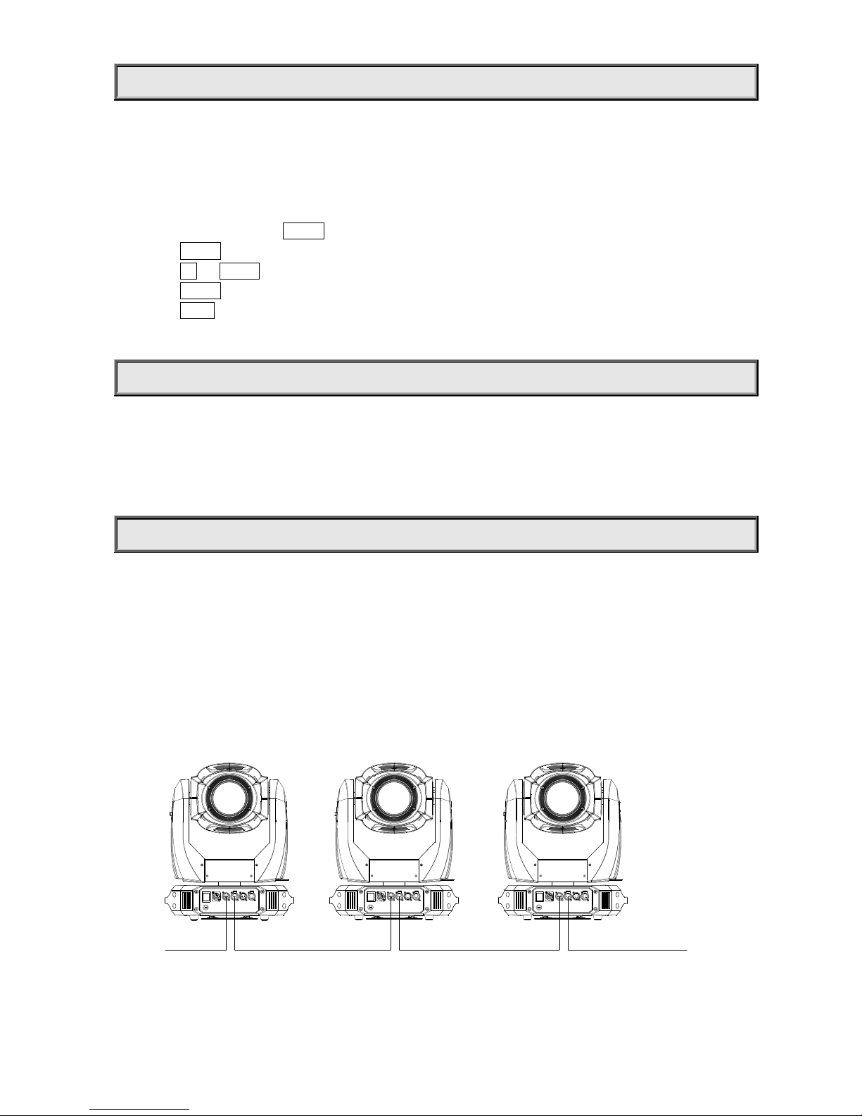
Connect the controller’s DMX output to the first fixture’s DMX input, and connect the first fixture’s DMX output to the second
fixture’s DMX input and connect the rest fixtures in the same way Eventually connect the last fixture’s DMX output to a DMX
terminator as shown in the figure below

6/24
DMX
Controller
DMX512
Input Output Input Output Input
DMX
Terminator
DMX TERMINATOR
In the Controller mode, at the last fixture in the chain, the DMX output has to be connected with a DMX terminator This prevents
electrical noise from disturbing and corrupting the DMX control signals
The DMX terminator is simply an XLR connector with a 120Ω (ohm) resistor connected across pins 2 and 3, which is then plugged
into the output socket on the last projector in the chain The connections are illustrated below
SETUP OPTIONS-PROJECTOR CONFIGURATION
PR
W- MXMX
Projector configuration can be set conveniently via push button and LCD display
Launch the projector and press button ENTER for more than 2 seconds to unlock the panel, the LCD will show the function menu of
the projector, each main menu has its submenus and each submenu has a specific function For details, please see the
“OPERATION MENU” section
Press button UP or DOWN if you want to browse through the various Setup Options
Press button ENTER to save your settings or enter the submenu
Press button UP or DOWN to change values(plus or minus)
Press button FUNC, it will return to the upper menu If button FUNC not pressed, the default will show display status automatically
21
3
120
MX TERMINATOR
CONNECTION
Connect a 120 (OHM) resistor
across pins 2 and 3 in an XLR plug
and insert into the MX out socket
on the last unit in the chain.
PIN 3
PIN 2
7/24
TO SET THE DMX START ADDRESS
Each XR 330 BWS must be given a DMX start address so that the correct projector responds to the correct control signals This
DMX start address is the channel number from which the projector starts to “listen” to the digital control information being sent out
from the controller The XR 330 BWS has 3 DMX modes There are standard mode ,short mode and extended mode For
example standard mode has 26 channels, so set the No 1 projector’s address 001, No 2 projector’s address 027, No 3 projector’s
address 053, No 4 projector’s address079, and so on
Launch the projector Press button ENTER more than 2seconds to unlock panel
Press button ENTER to display DMX address;
Press button UP and DOWN, you can set the address;
Press button ENTER to confirm; after powered on next time, the default will be last value saved
Press button FUNC, it will return to the upper menu
STAND-ALONE MODE
Operate the projector without connecting with a controller, enable the master mode through the operation panel, the
projector will run in Stand-Alone mode automatically
DMX address can be set at any number within 512
MASTER/SLAVE MODE
Many projectors can run synchronously in the Master/Slave mode by linking them with each other First,
connect the first fixture’s DMX output to the second fixture’s DMX input using XLR-XLR control cable and then connect the second
fixture’s DMX output to the third fixture’s DMX input, and so on until all projector are connected in this way Eventually connect the
last fixture’s DMX output to a DMX terminator Set 1st projector as the master and others are Slaves
Start Addresses of all Slaves are 001; Operation mode of the Master can be set any mode for a Master’ and Slaves’ operation mode can
be set accordingly
Input Output Input Output Input
DMX
Terminator
Master Slave Slave

8/24
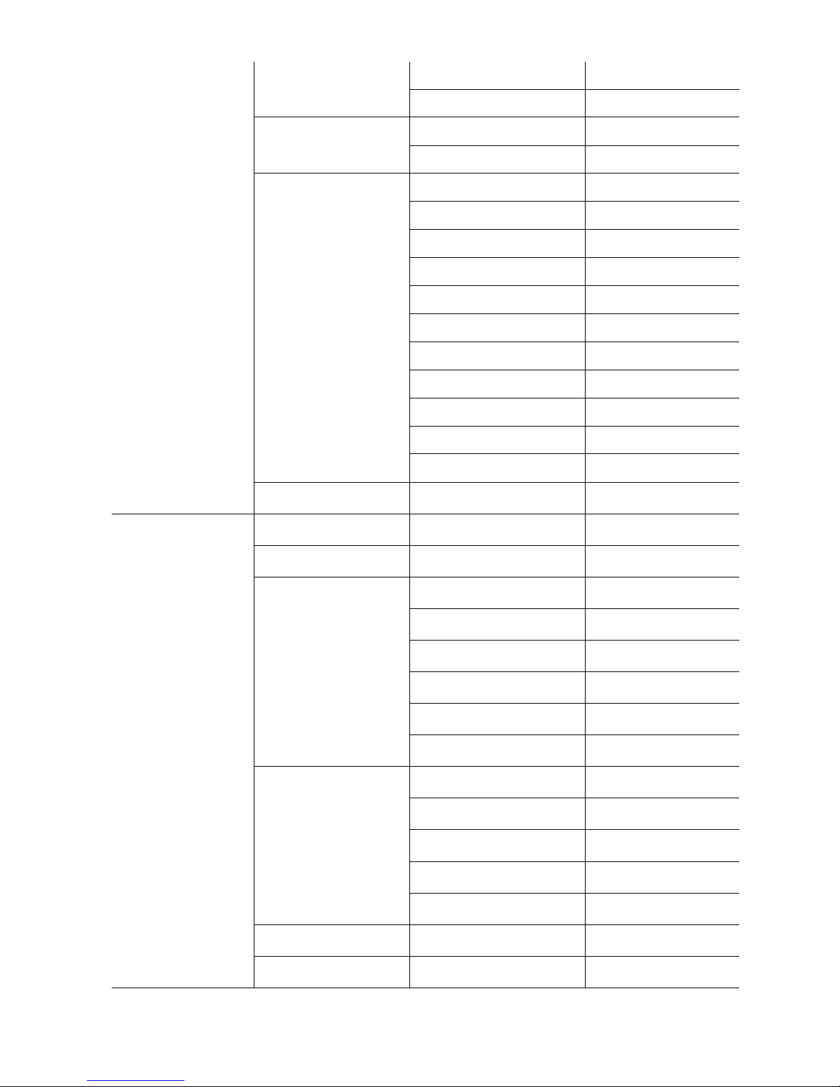
OPERATION MENU
First Menu Secondary Menu hird Menu Fourth Menu
DMX Address DMX Address=XXX
Reset
Are You Sure
Config Settings
DMX Mode
Standard
Extended
Short
Lamp Control
By Control Channel
By Power On
By DMX Present
Loss of DMX
When DMX is Lost
Normal time out
When DMX is Lost
Hold Last Value
Factory Settings
(Press button
DOWN/UP/ENTER at the same
time to enter the sub-menu)
Fixture Type
(WARNING: Never change the fixture
type ,otherwise the system will be
damaged!)
Option Settings
Color Positions
Color Positions
STEPPED
Color Positions
LINEAR
F-Gobo Positions
F-Gobo Positions
STEPPED
F-Gobo Positions
LINEAR
Pan DMX Invert
Pan DMX Invert
OFF
Pan DMX Invert
ON
Tilt DMX Invert
Tilt DMX Invert
OFF
Tilt DMX Invert
ON
Pan Tilt Swap
Pan Tilt Swap
OFF
Pan Tilt Swap
ON
Dimmer Invert
Dimmer Invert
OFF
Dimmer Invert
ON
Zoom Invert
Zoom Invert
OFF
Zoom Invert
ON
CYM Invert
CYM Invert
OFF
CYM Invert
ON
Defaults
Defaults
OFF
Defaults
Restore Defaults
9/24
Display Options
Display Mode
Display
On Always
Display
Off After Delay
Display Invert
Display Invert
OFF
Display Invert
ON
Display Dimming
Disp Dim Level
Min
Disp Dim Level
1
Disp Dim Level
2
Disp Dim Level
3
Disp Dim Level
4
Disp Dim Level
5
Disp Dim Level
6
Disp Dim Level
7
Disp Dim Level
8
Disp Dim Level
9
Disp Dim Level
Full
Display Contrast
Display Contrast
XX(1~21)
Information
Lamp Hours Lamp Hours=
XX
Reset Lamp Hours
Are You Sure(UP/DOWN)
Total Hours Total Hours=
XX
Temperature
Display Board Display Board=
XX℃
Driver Board 1 Driver Board 1=
XX℃
Driver Board 2 Driver Board 2=
XX℃
Driver Board 3 Driver Board 3=
XX℃
Pan and Tilt Board Pan and Tilt=
XX℃
Head Sensor Head Sensor=
XX℃
Software Version
Display Board Display Board=
X X X
Driver Board 1 Driver Board 1=
X X X
Driver Board 2 Driver Board 2=
X X X
Driver Board 3 Driver Board 3=
X X X
Pan and Tilt Board Pan and Tilt=
X X X
View DMX Values DMX Channel
1=XXX
Electronic SN Electronic SN=
************

10/24
RDM Device Label
RDM Device Label
ANSI E1 20 RDM
Version X X
Pan Encoder
Wiring Normal
Pan Err 0
Count 50880
Tilt Encoder
Wiring Normal
Tilt Err 0
Count 28080
Driver Faults
X Over Temp 0
Y Over Temp 0
X Fault 0
Y Fault 0
Test Modes
Factory Setup
Factory Setup
OFF
Factory Setup
ON
Self Test
Self Test
OFF
Self Test
ON
Lamp Manual Control
Lamp Status S= X C= X
Lamp On
Turn Lamp On
Turn Lamp Off
Wireless Options
Wireless Mode
Wireless Mode
XLR First
Wireless Mode
Wireless Only
Wireless Mode
XLR Only
Wireless Mode
Wireless To XLR
Wireless Mode
Wireless First
Un-Link Wireless
Really Un-Link
Enter=Yes
Operation Mode
Operation Mode=
DMX
Operation
Operation Mode=
Master Mode
User’s Memory 1
User’s Memory 2
Operation Mode=
Slave Mode
User’s Memory 1
User’s Memory 2
Operation Mode=
Static Scene
User memories Edit User Memory User Memory 1 Scene XX
(1~200scenes)
Shutter Shutter XXX
Dimmer Dimmer XXX
Dimmer Low Dimme Low XXX
CYM Macros CYM Macros XXX
Cyan Cyan XXX
Yellow Yellow XXX
Magenta Magenta XXX
Color Wheel Color Wheel XXX
Fixed Gobo Fixed Gobo XXX
R Gobo Wheel R Gobo Wheel XXX
R Gobo Rotate R Gobo Rotate XXX
R Gobo Roate L R Gobo Roate L XXX

11/24
R Prism In Out R Prism In Out XXX
R Prism Rotate R Prism Rotate XXX
R Prism2 In Out R Prism2 In Out XXX
R Prism2 Rotate R Prism2 Rotate XXX
Frost Frost XXX
Focus Focus XXX
Zoom Zoom XXX
Diffuser Diffuser XXX
Pan Coarse Pan Coarse XXX
Pan Fine Pan Fine XXX
Tilt Coarse Tilt Coarse XXX
Tilt Fine Tilt Fine XXX
M-Speeds M-Speeds XXX
(
000~255
)
Delay Delay XX s
(
0 25s~100min
)
Link To Step Link To Step
XXX(1~200)
Use Memory 2 Scene XX
(1~200scenes)
Shutter Shutter XXX
Dimmer Dimmer XXX
Dimmer Low Dimmer Low XXX
CYM Macros CYM Macros XXX
Cyan Cyan XXX
Yellow Yellow XXX
Magenta Magenta XXX
Color Wheel Color Wheel XXX
Fixed Gobo Fixed Gobo XXX
R Gobo Wheel R Gobo Wheel XXX
R Gobo Rotate R Gobo Rotate XXX
R Gobo Roate L R Gobo Roate L XXX
R Prism In Out R Prism In Out XXX
R Prism Rotate R Prism Rotate XXX
R Prism2 In Out R Prism2 In Out XXX
R Prism2 Rotate R Prism2 Rotate XXX
Frost Frost XXX
Focus Focus XXX
Zoom Zoom XXX
Diffuser Diffuser XXX
Pan Coarse Pan Coarse XXX
Pan Fine Pan Fine XXX
Tilt Coarse Tilt Coarse XXX
Tilt Fine Tilt Fine XXX
M-Speeds M-Speeds XXX
(000~255)
Delay Delay XX s
(0 25s~100min)
Link To Step Link To Step
XXX(1~200)
Static Scene
Shutters Shutters XXX
Dimmer Dimmer XXX
Dimmer Low Dimmer Low XXX
CYM Macros CYM Macros XXX
12/24
CMY Cyan Cyan XXX
CMY Yellow Yellow XXX
CMY Magenta Magenta XXX
Color Wheel Color Wheel XXX
Fixed Gobo Fixed G-Wheel
XXX
R Gobo Wheel R Gobo Wheel
XXX
R Gobo Rotate R Gobo Rotate
XXX
R Gobo Roate L R Gobo Roate L
XXX
R Prism In Out R Prism In Out
XXX
R Prism Rotate R Prism Rotate
XXX
R Prism2 In Out R Prism2 In Out
XXX
R Prism2 Rotate R Prism2 Rotate
XXX
Frost Frost XXX
Focus Focus XXX
Zoom Zoom XXX
Diffuser Diffuser XXX
Pan Coarse Pan Coarse XXX
Pan Fine Pan Fine XXX
Tilt Coarse Tilt Coarse XXX
Tilt Fine Tilt Fine XXX
M-Speed M-Speed XXX
(
000~255
)
Init User memory
Reset User memory 1
Clear User’s memory
1?(Press buttons
2,3 4,ie buttons
UP/DOWN/ENTER to
execute the function)
User’s memory 1
cleared
Reset User memory 2
Clear User’s memory
2?(Press buttons
2,3 4,ie buttons
UP/DOWN/ENTER to
execute the function
)
User’s memory 2
cleared
Reset Static Scene
Clear single scene 1?
(Press buttons 2,3 4,ie
buttons
UP/DOWN/ENTER to
execute the function
)
Single Scene 1
cleared
13/24
ERROR MESSAGES
In the course of launch, Projector examines automatically whether there are errors and if there are, it will display
information as follows:
Sensor Err S1-M4 CYM-Cyan (1# drive board motor 4) error
Sensor Err S1-M5 CYM-Yellow (1# drive board motor 5) error
Sensor Err S1-M6 CYM-Magenta(1# drive board motor 6) error
Sensor Err S2-M1 8-facet Prism Move in/out (#2 board motor1)error
Sensor Err S2-M2 8-facet Prism Rotation (#2 board motor2)error
Sensor Err S2-M3 16-facet Prism Move in/out (#2 board motor3)error
Sensor Err S2-M4 16-facet Prism Rotation (#2 board motor4)error
Sensor Err S2-M5 Focus (2# drive board motor 5) error
Sensor Err S2-M6 Zoom (2# drive board motor 6) error
Sensor Err S3-M1 Color Wheel (3# drive board motor 1) error
Sensor Err S3-M2 Fixed Gobo Wheel(3# drive board motor 2) error
Sensor Err S3-M3 Rotating Gobo Wheel (3# drive board motor 3) error
Sensor Err S3-M4 Gobo Rotation(3# drive board motor 4) error
Over Temp Error Over Temp Error
Temp Sense Error Temp Sense Error
Head Fan 1 Fail Lamp Fan Fail
Head Fan2 Fail Head Fan1 Fail
Head Fan 3 Fail Gobo Fan Fail
Head Fan 4 Fail CMY Fan Fail
Pan Encoder Err Pan Encoder Err
Tilt Encoder Err Tilt Encoder Err
Pan Enc T Out Pan Enc T Out
Tilt Enc T Out Tilt Enc T Out
Pan Sensor Error Pan Sensor Error
Tilt Sensor Error Tilt Sensor Error
Pan Over Temp Pan Over Temp
Pan Driver Fault Pan Driver Fault
Tilt Over Temp Tilt Over Temp
Tilt Driver Fault Tilt Driver Fault
Pan Enc Rev Err Pan Enc Rev Err
Tilt Enc Rev Err Tilt Enc Rev Err
14/24
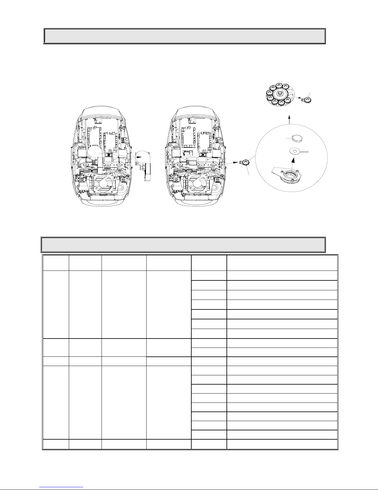
REPLACING GOBOS
Rotator
Gobo
Tightening
spring
Gobo replacement
1 As shown in figure1, disconnect a projector from power Unfasten the
4 fastfit screws of the cover to remove the cover, and unfasten the 2
screws of the fan assembly and remove the assembly
2 Pull out the rotator from the rotating gobo wheel forcefully by fingers as
shown in figure2 After replacing the gobo or the rotator, put the rotator
back to the holder
Figure 2
Figure 2
Rotator
Rotating gobo wheel
Figure 1
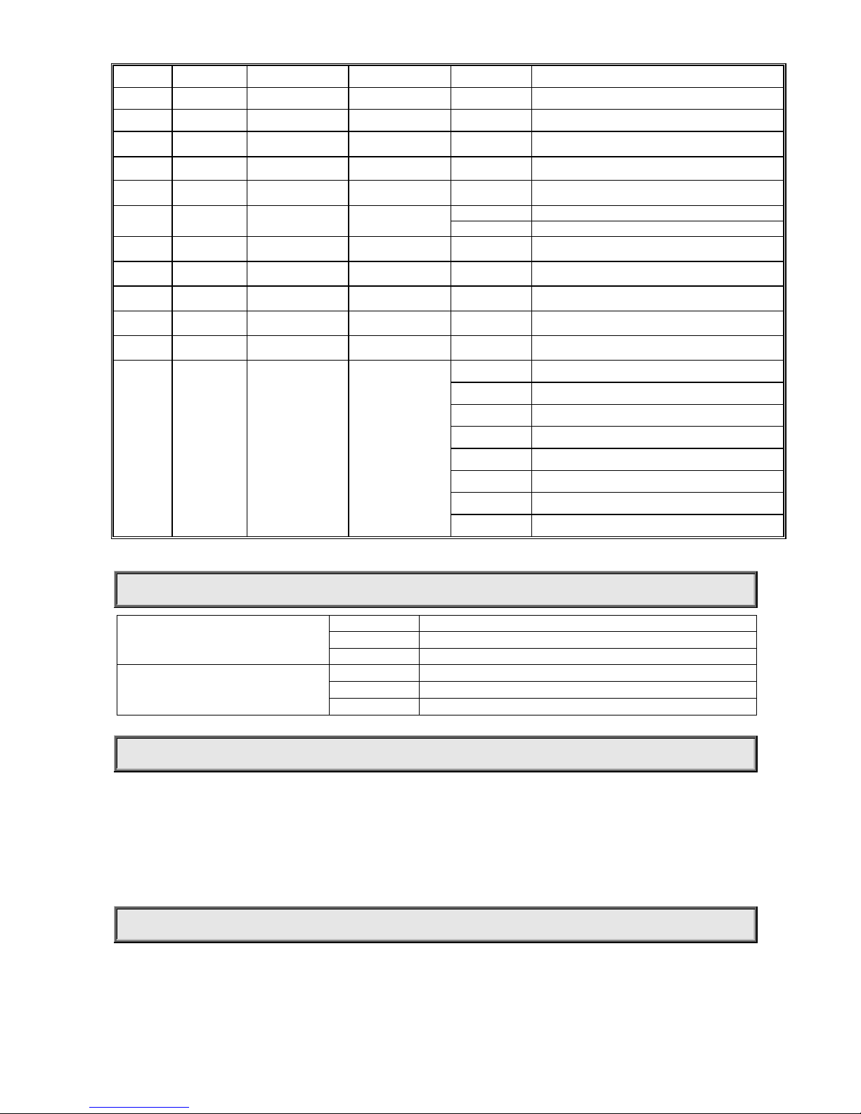
DMX PROTOCOL
Short
mode
Standard
mode
Extended
Mode FUNC ION DMX DESCRIP ION
1 1 1 Strobe
000-010 Close
011-025 Open
026-225 Strobe speed from slow to fast
226-239 Macro 1
240-241 Macro 2
242-246 Macro 3
247-255 Open
2
2
2
Dimming 000-035 Close
036-255 Linear dimming(0-100%)
3
3
Dimming Fine 0-255 Dimmer in 16 bit
3 4 4 CYM Macro
000-016 White
017-035 Yellow+ Magenta=Red
036-054 Yellow
055-073 Yellow +Cyan=Green
074-092 Cyan
093-110 Cyan + Magenta= Violet
111-128 Magenta
129-255 CYM color mixing from slow to fast
4 5 5 Cyan 000-255 Cyan (linear 0~100%)

15/24
6 Cyan in 16 Bit 000-255 Cyan 16 Bit
5 6 7 Yellow 000-255 Yellow (linear 0~100%)
8 Yellow in 16 Bit 000-255 Yellow in 16 Bit
6 7 9 Magenta 000-255 Magenta (linear 0~100%)
10 Magenta in 16 Bit
000-255 Magenta in 16 Bit
7 8 11 Color Wheel
000-010 White
011-019 Color 1
020-028 Color 2
029-037 Color 3
038-046 Color 4
047-055 Color5
056-064 Color6
065-073 Color7
074-082 Color8
083-091 Color9
092-100 Color10
101-110 Color11
111-119 Color12
120-128 Color13
129-191 Rotation ,Clockwise from slow to fast
192-255 Rotation, Anti-clockwise from slow to fast
8
9
12
Fixed Gobo
0-10 Open
11-19 Gobo1
20-27 Gobo2
28-36 Gobo3
37-45 Gobo4
46-57 Gobo5
58-66 Gobo6
67-75 Gobo7
76-84 Gobo8
85-93 Gobo9
94-102 Gobo10
103-111 Gobo11
112-119 Gobo12
120-127 Gobo13
128-149 Clockwise rotation from slow to fast
150-171 Anti Clockwise rotation from slow to fast
172-177 Shake effect 1 from slow to fast
178-183 Shake effect 2 from slow to fast
184-189 Shake effect 3 from slow to fast
190-196 Shake effect 4 from slow to fast
197-203 Shake effect 5 from slow to fast
204-210 Shake effect 6 from slow to fast
211-217 Shake effect 7 from slow to fast

16/24
218-224 Shake effect 8 from slow to fast
225-231 Shake effect 9 from slow to fast
232-237 Shake effect 10 from slow to fast
238-243 Shake effect 11 from slow to fast
244-249 Shake effect 12 from slow to fast
250-255 Shake effect 13 from slow to fast
9 10 13 Rotating Gobo
Wheel
000-012 White
013-025 Gobo 1
026-037 Gobo 2
038-050 Gobo 3
051-062 Gobo 4
063-075 Gobo 5
076-088 Gobo 6
089-101 Gobo 7
102-114 Gobo 8
115-127 Gobo 9
128-155 Rotation (clockwise From slow to Fast)
156-183 Reverse Rotation (anti-clockwise From slow to Fast)
184-191 Shake of Gobo 1
192-199 Shake of Gobo 2
200-207 Shake of Gobo 3
208-215 Shake of Gobo 4
216-223 Shake of Gobo 5
224-231 Shake of Gobo 6
232-239 Shake of Gobo 7
240-247 Shake of Gobo 8
248-255 Shake of Gobo 9
10 11 14 Gobo Rotation
000-128 Gobo Indexing(0~540degrees)
129-188 Rotation (Clockwise From slow to Fast)
189-195 Stop
196-255 Rotation (Anti-Clockwise From slow to Fast)
12 15
Gobo Rotation
Fine
0-255 Gobo Rotation in 16 Bit
11 13 16 Prism1 000-016 Open
017-255 Prism
12 14 17 Prism1 Rotation
000-128 Prism Indexing
129-191 Rotation(Clockwise from slow to fast)
192 Stop
193-255 Rotation(Anti- Clockwise from slow to fast)
13 15 18 Prism2 000-016 White
017-255 Prism
14
16
19 Prism2 Rotation
000-128 Prism Indexing
129-191 Rotation(Clockwise from slow to fast)
192 Stop
17/24
193-255 Rotation(Anti- Clockwise from slow to fast)
15 17 20 Frost Filter 000-255 Linear Frost
16 18 21 Focusing 000-255 Linear Focusing
22 Focusing Fine 000-255 Focusing in 16 bit precision
17 19 23 Zoom
000
-
255
Linear Zooming
24 Zooming Fine
000
-
255
Linear Zooming in 16 bit precision
18 20 25 Diffuser
000
-
016
Open
017
-
255
Diffuser
19 21 26 Pan 000-255 Pan(0°~540°)
22 27 Pan Fine 000-255 Pan in 16 bit precision
20 23 28 Tilt 000-255 Tilt(0°~270°)
24 29 Tilt Fine 000-255 Tilt in 16 bit precision
25 30 Pan & Tilt Speeds
000-255 Pan & Tilt Speed from Fast to Slow
21 26 31 Control
000-047 Reserved
048-080 Reset
081-112 Reserved
113-144 Lamp Off ( Delay for 3 s)
145-168 Reserved
169-200 Lamp Half Power
201-223 Reserved
224-255 Lamp Full Power
Remark: Prism is prior to Frost
LED INDICATION
DMX Indication
On DMX signal OK
Off No DMX signal
Flash DMX signal error
W-DMX Indication
ON Wireless DMX Signal available
OFF Not linked to any transmitter
Flash Lose link with a transmitter or being linked with one
MAINTENANCE
If the projector’s lens becomes damaged or broken it should be replaced If the lamp becomes damaged or deformed in any way it
must be replaced If the light from the lamp appears dim this would normally indicate that it is reaching the end of its life and it should
be changed at once, aged lamps run to the extremity of their life might explode If the projector does not function, check the fuses on
the power socket of the projector, they should only be replaced by fuses of the same specification The projector has overheat
protection device that will switch off the projector in case of overheating Should it happen, check if the fans are blocked or not, or if
they are dirty, clean them before switching on the projector again
Any maintenance work should only be carried out by qualified technicians.
LUBRICATION
To ensure the smooth rotation of the rotating gobos and movement of the lens for focusing, it is recommended that the bearings for
the rotating gobos and the 2 sliding tracks for the focusing lens holder be lubricated every two months Use only high quality,
high-temperature grease
18/24
KEEPING THE PROJECTOR CLEAN
To ensure the reliability of the projector it should be kept clean It is recommended that the fans should be cleaned every 15 days
The lens and dichroic colour filters should also be regularly cleaned to maintain an optimum light output Do NO use any type of
solvent containing chemical elements on dichroic colour filters.
Cleaning frequency depends on the environment in which the fixture operates A soft cloth and typical glass cleaning products
should be used in cleaning It is recommended to clean the external optics at least once every 20 days and clean the internal optics at
least once every 30 / 60 days
Do not use any organic solvent, e.g. alcohol, to clean the reflector mirror, dichroic colour filters or housing of the apparatus.
TROUBLESHOOTING
PROBLEM AC ION
The projector doesn’t switch on Check the fuse on the power socket
Check the lamp
The lamp is on but the projector doesn’t respond
to the controller
Make sure that the fixture’s start address is right
Replace or repair the XLR signal cable
The projector functions intermittently Make sure the fan is working well or fans and their shields are not blocked
Beam appears dim, Low in brightness Make sure the lamp is within its lifespan
Remove dust or grease from the lenses
The project image appears to have a halo Carefully clean the lamp, optical lenses and other components
Heavily Defective Beam Check if lens are in good condition(not cracked)
Clean dust or grease on the lens

19/24
TECHNICAL DATA
VOL AGES:
100V~240V AC,50/60Hz
POWER CONSUMP ION:
450W@220V
LAMP:
OSRAM
SIRIUS HRI 330W
Colour Temperature 7500K
Manufacturers Rated Lamp Life 1500hours
Colors:
CMY linear mixing system with macros
1 color wheel: 13colors(plus 1CTO)+ Open
rainbow effect with bi-directional and variable speeds
Stepping/linear color changing
Fixed Gobo Wheel
1 fixed gobo wheel: 13 gobos +open
bi-directionally rotatable, and shakable at variable speeds
Rotating Gobo Wheel
1 Rotating gobo wheel:
9 interchangeable gobos+1white
bi-directionally rotatable, and shakable at variable speeds
Gobo diameter: Φ15 9mm
Gobo image diameter: Φ13mm
PRISM:
2pcs,(STD 8-facet and 16 facet Prisms) Bi-directional rotation with variable speeds(options: 3facet, 16 facet, liner prism, gradient prism)
Independent Diffuser
Optional even beam mode
FROS FIL ER:
1pc frost filter
FOCUSING:
DMX linear Focusing

20/24
ZOOMING:
DMX linear Zooming
DIMMER/S ROBE:
0-100% linearly adjustable/ Double shutter blades, 0 3~25 FPS
HEAD MOVEMEN :
Pan 540º, Tilt 270º with auto position correction
BEAM ANGLE:
Beam: 2 3°-- 10°, Linear Adjustment
Spot 5°-- 22°Linear Adjustment
Wash 5°-- 40°Linear Adjustment
CON ROL:
DMX512, 3 pin and 5 pin interfaces
21channels in short mode, 26channels in standard mode and 31channels in extended mode
Self-test mode
O HER FUNC IONS:
Adjustable Pan & Tilt speed
Lamp’s and fixture’s hours displayed
Modular Structure for easy maintenance
DMX512 wirless signal
Optional DMX512 Transmitter
HOUSING:
High temperature ABS, IP20
NE WEIGH :
22 2Kg
Gross Weight
79Kg in flight case(2pcs/case) and accessories
26 5Kg in carton(1pc/ctn) and accessories
Table of contents


