TWEETER DIAPHRAGM REPLACEMENT FOR THE LFT-8b
Revised 10/26/2007
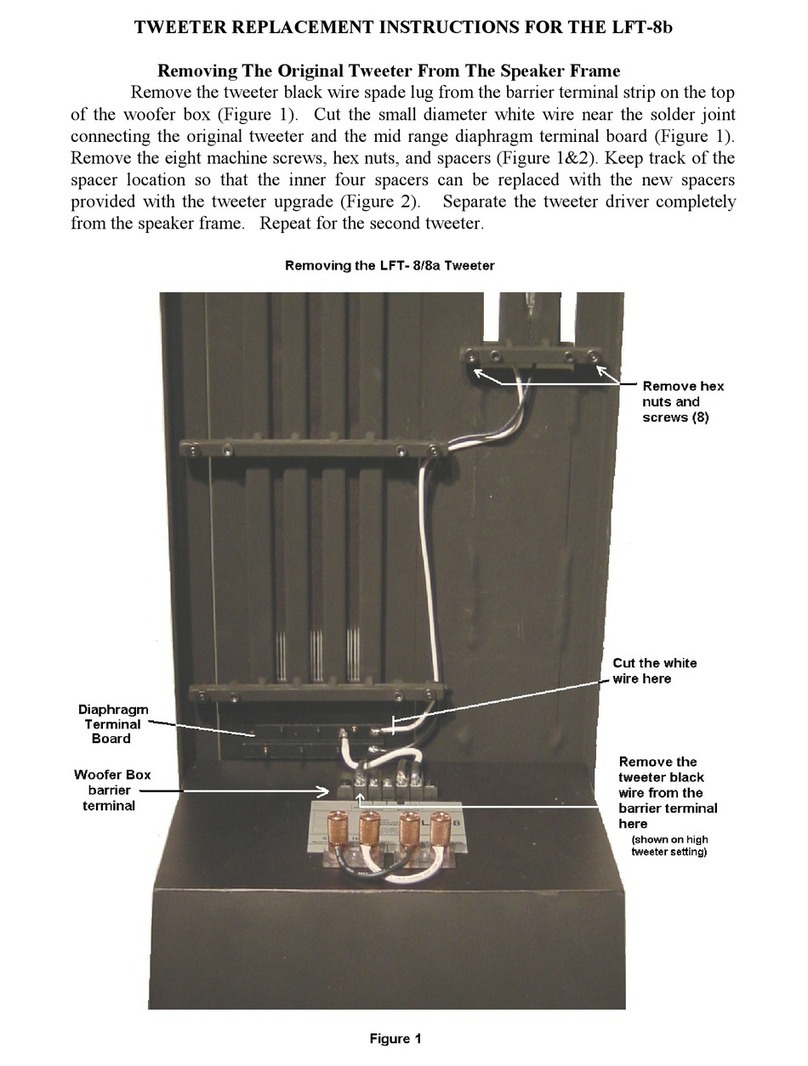
Remove the tweeter driver completely from the speaker frame. Disconnect the
black tweeter wire spade lu from the barrier terminal block and detach the white tweeter
wire from the mid-ran e terminal board usin a solderin iron. Remove the ei ht
machine screws, nuts and spacers. Keep track of each spacer location so that it can be
returned to that same position upon re-assembly. Place the tweeter driver on a smooth,
clean surface with its front assembly, facin down. Remove four 10-32 machine screws
from one end of the tweeter driver assembly. Pull apart the back ma net assembly from
the front (approx. 1”) at this end. Continue pullin apart the channels while removin the
next three pairs of screws, takin care not to allow the front and back channels to slap
to ether. Loosen the remainin screw at the end and pivot the top channel clear of the
bottom channel at ri ht an les from each other. Remove the screw and separate the two
halves.
Replacing The Tweete Diaph agm
Remove the old diaphra m alon with the underlyin double-sided tape on both
rows of ma nets from “front” channel makin sure the rubber insulator squares stay
intact. Please note placement and location of the diaph agm befo e emoval, as to
efe ence the location fo the eplacement diaph agm. Check for and remove any
ma net fra ments from the front and back channels. Place the new tweeter diaphra m on
a hard top table with the terminal board facin down and aluminum conductor facin up.
Tape the non-terminal end of the diaphra m to the table usin ½” wide invisible (office)
tape. Tension and tape the other end of the diaphra m just above the terminal board
usin a 3” piece of invisible tape. Make sure the diaphra m is flush with the table with
no wrinkles or creases above the terminal board. Place an 18 ¾” piece of ½” wide
double-sided tape on the outer three conductor ribbons of the diaphra m, startin at the
non-terminal end and endin around 4 ½” from the terminal board. Cover the final 3” of
conductor ribbons, includin the terminated leads, with invisible tape. Carefully remove
the diaphra m for the table and place the diaphra m by first attachin the non-terminal
end flush with either end of the front channel assembly. Next, tension the diaphra m and
ali n the conductors with the channel while pushin the diaphra m onto the ma nets
makin sure the diaphra m is flat between the ma net channels as you o. The
diaphra m should resemble Diag am (A). Fold and tape the over-han in terminal end
of the diaphra m as illustrated in Diag am (B).
