Pramac P2000i User manual

INVERTER GENERATOR
P2000i
Operating Manual

INVERTER GENERATOR – P2000i
2
We Appreciate Your Business.
Thank you and congratulations on choosing PRAMAC.
This Operating Manual has been designed to instruct you on the correct use
and operation of your PRAMAC product. Your satisfaction with this product
and its safe operation is our ultimate concern. Therefore please take the time
to read the entire manual, especially the Safety Precautions. They will help
you to avoid potential hazards that may exist when working with this product
.
WARNING
READ AND
UNDERSTAND ALL SAFETY PRECAUTIONS IN THIS MANUAL BEFORE
OPERATING. FAILURE TO COMPLY WITH INSTRUCTIONS IN THIS MANUAL COULD
RESULT IN PERSONAL IN
JURY, PROPERTY DAMAGE, ANDIOR VOIDING OF YOUR
WARRANTY. PRAMAC WILL NOT BE UABLE FOR ANY DAMAGE BEC
AUSE OF FAILURE
TO FOLLOW THESE INSTRUCT/ONS.

INVERTER GENERATOR – P2000i
3
Table of Contents
1SAFETY INSTRUCTIONS AND WARNINGS ......................................... 4
2CONTROLS AND FEATURES.............................................................. 12
2.1 Generator ......................................................................................... 12
2.2 Control Panel .................................................................................... 13
2.3 Control Functions ............................................................................. 14
3GETTING STARTED............................................................................. 18
3.1 Unpack the Generator ...................................................................... 18
3.2 Adding engine Oil ............................................................................. 18
3.3 Adding Fuel ...................................................................................... 20
3.4 Starting the Engine ........................................................................... 21
3.5 Stopping the Engine ......................................................................... 23
4ELECTRICAL CONNECTION............................................................... 24
4.1 Capacity ........................................................................................... 24
4.2 Power Management ......................................................................... 24
4.3 Connecting Electrical Loads ............................................................. 24
4.4 Parellel Connection within 2 generator ............................................. 25
4.5 Battery Charging ............................................................................... 28
4.6 Wattage Reference Guide ................................................................ 29
5MAINTENANCE.................................................................................... 31
5.1 Periodic Maintenance ....................................................................... 31
5.2 Spark Plug Maintenance ................................................................... 32
5.3 Engine Oil Replacement ................................................................... 33
5.4Air Filter Maintenance ....................................................................... 34
5.5 Muffler Screen and Spark Arrestor Maintenance .............................. 35
5.6 Fuel Filter Maintenance .................................................................... 36
6STORAGE............................................................................................. 37
6.1 Long Term Storage ........................................................................... 37
7TROUBLESHOOTING AND SPECIFICATIONS................................... 39
7.1 Troubleshooting Diagram ................................................................. 39
7.2 Fuel Filter Maintenance .................................................................... 40
7.3 Specifications ................................................................................... 41

INVERTER GENERATOR – P2000i
4
1 SAFETY INSTRUCTIONS AND WARNINGS
WARNING
THE ENGINE EXHAUST FROM THIS PRODUCT CONTAINS CHEMICALS TO CAUSE
CANCER, BIRTH DEFECTS OR OTHER REPRODUCTIVE HARM.
NOTE
Read this manual carefully before operating this machine. This manual should stay with this
machine if it is sold.

INVERTER GENERATOR – P2000i
5
INTRODUCTION
This Operating Manual has been designed to instruct you on the correct
operation of your PRAMAC product. Your satisfaction with this product and its
safe operation is our ultimate concern. Therefore please take the time to read
the entire manual, especially the Safety Precautions. They will help you to
avoid potential hazards that may exist when working with this product.

INVERTER GENERATOR – P2000i
6
IMPORTANT MANUAL INFORMATION
Particulary important information is distinguished in this manual by the
following notes.
Symbol Usage
This manual contains important information that you need to know and
understand in order to assure YOUR SAFETY and PROPER OPERATION
OF EQUIPMENT. The following symbols help you recognize this
information. Please read the manual and pay attention to these
sections.
WARNING
WARNING INDICATE A CERTAINTY OR STRONG POSSIBILITY OF PERSONAL INJURY OR
DEATH IF INSTRUCTIONS ARE NOT FOLLOWED.
NOTICE
CAUTIONS INDICATE A POSSIBILITY ARE NOT FOLLOWED PROPERLY.
TIPS
TIPS GIVE HELPFUL INFORMATION
WARNING
PLEASE READ AND UNDERSTAND THIS MANUAL COMPLETELY BEFORE OPERATING
THE MACHINE.
TIP
Continually seeks advancements in product design and quality. Therefore,
wherein this manual contains the most current product information available
at the time of printing, there may be minor discrepancies between your
engine and this manual. If there is any question cancerning this manual,
please consult a PRAMAC dealer.
This manual should be considered a permanent part of this engine and
should remain with this engine when resod.
Product and specifications are subject to change without notice.

INVERTER GENERATOR – P2000i
7
SAFETY INFORMATION
FUEL IS HIGHLY FLAMMABLE AND POISONOUS
• Always turn off the engine when refueling.
• Never refuel while smoking or in the vicinity of an open flame.
• Take care not to spill any fuel on the engine or muffler when refueling.
• If you swallow any fuel, inhale fuel vapor, or allow
• Any to get in your eye(s), see your doctor immediately. If any fuel spills
on your skin or clothing, immediately wash with soap and water and
change your clothes.
• When operating or transporting the machine, be sure it is kept upright. If
it tilts, fuel may leak from the carburetor or fuel tank.
EXHAUST FUMES ARE POISONOUS
• Never operate the engine in a closed area or it may cause
unconsciousness and death within a short time. Operate the engine in a
well ventilated area.
ENGINE AND MUFFLER MAY BE HOT
• Place the machine in a place where pedestrians or children are not likely
to touch the machine.
• Avoid placing any flammable materials near the exhaust outlet during
operation.

INVERTER GENERATOR – P2000i
8
• Keep the machine at least 1m (3 ft) from buildings or other equipment, or
the engine may overheat @ 1 m (3 ft).
• Do not operate the engine with a dust cover, or other objects covering it.
• When covering the generator, be sure to do so only after the engine and
muffler have completely cooled down.
• Be sure to carry the generator only by its carrying handles.
• Do not place any obstacles on the generator.
ELECTRIC SHOCK PREVENTION
• Never operate the engine in rain or snow.
• Never touch the machine with wet hands or electrical shock will occur.

INVERTER GENERATOR – P2000i
9
• Connect the ground lead of the machine to the ground terminal 1 to
ground the generator to earth (where needed) and connect the end to
the ground electrode buried in the ground.
CONNECTION NOTES
• Avoid connecting the generator to commercial power outlet.
CONNECTION
WARNING
Before the generator can be connected to a building’s electrical system, a licensed
electrician must install an isolation (transfer) switch in the building’s main fuse box. The
switch is the connection point for generator power and allows selec
tion of generator or
main line power to the building. This will prevent the generator from charging the main
power line (back feeding) when the main power supply has failed or has been turned off for
line repair. Back feeding can electrocute or injure line
maintenance personnel. Also,
generator and building electrical system damage can occur when normal operating power
returns if unit is used without an isolation switch.
EXTENSION CORD NOTES
Extension cords should be protected by a tough flexible rubber sheath (I E C
245) or the equivalent to withstand mechanical stress.

INVERTER GENERATOR – P2000i
10
LOCATION OF IMPORTANT LABELS
Please read the following labels carefully before operating this machine.
TIP
Maintain or replace safety and instruction labels, as necessary.
1

INVERTER GENERATOR – P2000i
11
2
3

INVERTER GENERATOR – P2000i
12
2 CONTROLS AND FEATURES
2.1 Generator
1. Muffler
2. Carrying handle
3. Vented Gas Cap
4. Recoil Starter
5. Control Panel
6. Fuel Gauge
7. Exhaust and Spark Arrestor
8. Oil filter cap

INVERTER GENERATOR – P2000i
13
2.2 Control Panel
AC Pilot Light
1. Engine Switch
2. Economy Throttle (Black)
3. AC Pilot Light
4. Overload Indicator Light
5. Oil Warning Light
6. 12V DC Output
7. 8A DC Circuit Breaker
8. Fuel Petcock
9. Choke
10. 220/230/240V AC Outlets
This socket is only corresponding to a client, the different laws and regulations according to the sales area
changes corresponding to the socket.
11. Ground Terminal
INVERTER GENERATOR – P2000i
14
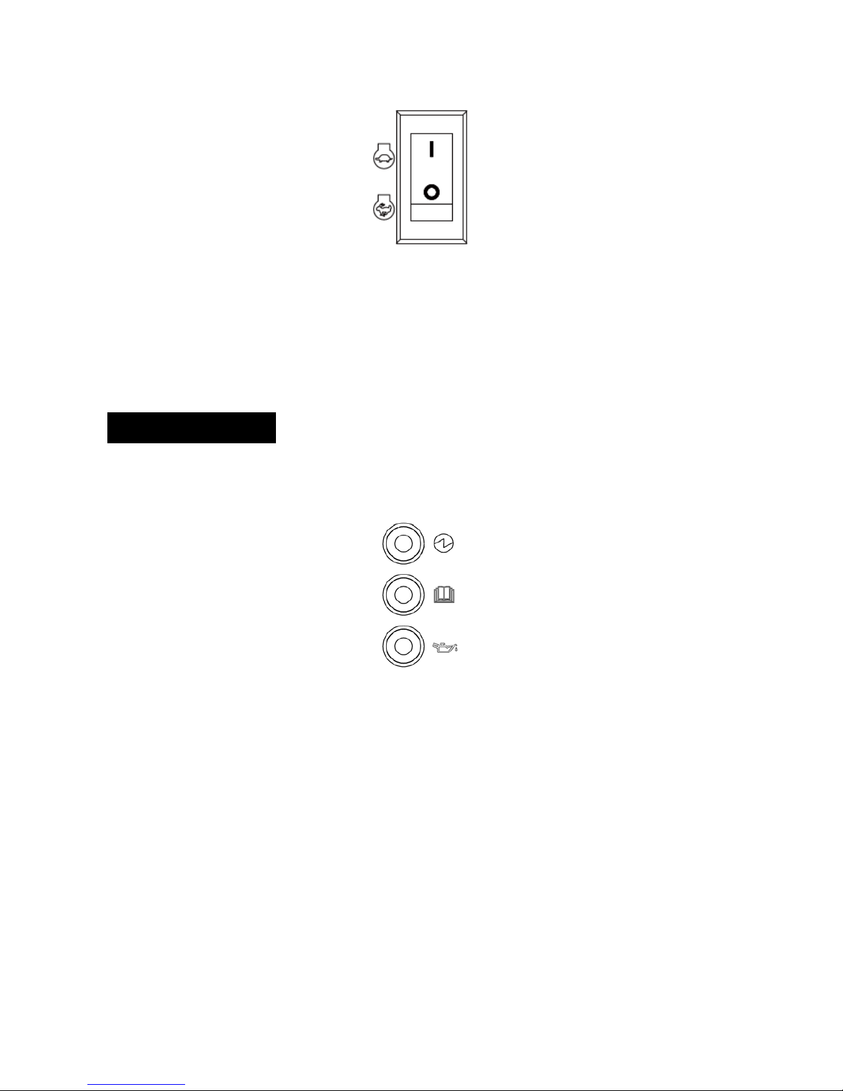
2.3 Control Functions
ECONOMY THROTTLE
Throttle
When the Throttle switch is in the “I” position the throttle controls the engine
speed according to the connected electrical load. The results are better fuel
consumption and less noise. When the switch is in the “O” position the engine
runs at 4,500 rpm regardless of the electrical load.
NOTE
The Throttle must be “O” when using electrical devices that require a large starting current,
such as a compressor, pump, or refrigenator.
Led Indicators
The LED Indicators assist in communicating proper and improper functions of
the unit.
Output Indicator (Green)
The Output Indicator comes on when the engine starts and produces power.
Overload Alarm (Red)
The Overload Alarm comes on when a connected device requires more
power than the generator is able to produce, the inverter control unit
overheats, or the AC output voltage rises above rated values. The Output
Indicator (Green) will go off and the Overload Alarm (Red) will stay on, but the
engine will continue to run.
When the Overload Alarm Light comes on and power generation stops,
proceed as follows:

INVERTER GENERATOR – P2000i
15
1. Turn off any connected electric devices and stop the
engine.
2. Reduce the
total wattage
of connected electric devices within
the
rated
output.
3. Check for blockages in the cooling air inlet and around
the
contro
l
unit.
lf any
blockages
are found remove
them.
4. After
checking, restart
the
engine.
NOTE
The Overload Alarm may come on for a few seconds when first using electrical devices that
require a large starting current, such as a compressor, pump, or refrigerator.
This is normal
behavior it is not a malfunction.
Low
Oil Alarm
(
Red)
When the engine oil falls below the required
level the
Low
Oi
l
Alar
m
will
come on and the engine will stop automatically. The engine will not restart
until oil is added to the unit to bring it up to the appropriate level.
NOTE
When starting the unit, if the Low Oil Alarm light flickers and the engine will not start, you
will need to add engine oil before attempting to restart the engine.
NOTE
Generator should
only be operated on a level surface. DO NOT operate the generator on
loose ground or obvious inclines. The low oil shutdown feature may be prematurely
activated in these cases causing the engine to not start.
Engine
Switch
The Engine Switch controls the
ignition switch.
Th
e
switch must be in the
“I”
position to start the
generator. Switching
to
the
“O”
position stops the
engine and
will
not allow the engine to be
restarted.

INVERTER GENERATOR – P2000i
16
12V 8A DC Outlet
The 12V 8A DC Outlet is for provided for battery charging. Follow instructions
in the owner’s manual for the battery for charging procedures.
8A DC Circuit Breaker
The 8A DC Circuit Breaker turns off automatically if the current exceeds 8A. If
the circuit breaker turns “O” you will need to push it “in” to turn it “I” again.
Fuel Petcock
The fuel Petcock controls the flow of gasoline from the fuel tank to the
carburetor. The Petcock knob should be in the “I” position when starting and
operating the generator. The Petcock knob should be in the “O” position when
the engine is not running and when storing or transporting the unit.
NOTE
The Fuel Petcock knob helps to prevent stale fuel from remaining in the carburetor while
storing or transporting the unit. Run the fuel out by turning the knob to the “O
” position and
letting the engine run until it stops.
Choke
The Choke is used when starting the engine “cold” (the engine is not hot).
Pull out fully on the choke when starting the engine. Once the engine has
warmed and a steady idle is achieved, push in on the choke. When restarting
a warm engine the choke is not necessary.

INVERTER GENERATOR – P2000i
17
220/230/240V AC Outlets
The Outlets are used to power 220/230/240V Single Phase 50Hz loads
requiring up to 1600W continuous power.
This socket is only corresponding to a client, the different laws and
regulations according to the sales area changes corresponding to the socket.
Ground Terminal
The Ground (Earth) terminal is used to ground the generator when grounded
electrical devices are being used. Consult an electrician for local grounding
regulations.

INVERTER GENERATOR – P2000i
18
3 GETTING STARTED
3.1 Unpack the Generator
Remove the generator from its packaging.
WARNING
Packaging is flammable! Do not attempt to add fuel to this unit before removing it from
packaging.
Inspect the generator to ensure that no damage has occurred in shipping or
handling. If the unit appears to be damaged, DO NOT add fuel or attempt to
start the generator. Please call PRAMAC costumer service.
Check to ensure that you received the following items:
• P 2000i 2000W Generator
• Parallel Cables
• Oil Funnel
If you did not receive any of the above items, please contact PRAMAC
costumer service.
3.2 Adding engine Oil
The generator has been shipped without engine oil. DO NOT add fuel or start
the engine before adding engine oil.
Figure 1
NOTE
In order to add motor oil you will need to remove the side panel from the unit.

INVERTER GENERATOR – P2000i
19
Using a #2 Phillips-head screwdriver remove screws 1 and 2 (seen in figure
1) and lift up and away to remove the side panel.
Figure 2
Place the generator on a level surface. DO NOT tilt the generator while
adding oil. It can cause you to overfill the oil and/or cause the oil to leak into
areas in which it is not intended.
Remove the oil filler cap 1 (seen in figure 2).
Figure 3
Using the funnel (provided) fill with 0.4 L of SAE 10W-30 or 10W-40
(provided) (see figure 3). See figure 4 for proper oil level 1.
Figure 4
Replace oil filler cap and secure side panel with screws.
Recommended engine oil:
A. YAMALUBE4(10W-40)
SAE10W-30or10W-40
B. SAE #30

INVERTER GENERATOR – P2000i
20
C. SAE#20
D. SAE#10W
Recommended engine oil grade: API Service SE type or higher Engine oil
quantity:
0.4L
3.3 Adding Fuel
The fuel tank capacty 4.1 Liter.
DO NOT overfill the tank, otherwise it may overflow when the fuel warms up
and expands.
NOTE
For safety reasons, once fuel has been added to this unit it cannot be returned to the place
of purchase.
1. Use clean, fresh, regular unleaded fuel with a minimum octane rating of
85.
2. DO NOT mix oil with fuel.
3. Clean area around the fuel cap.
4. Remove the fuel cap.
5. Be sure that the fuel strainer is in place.
6. Slowly add fuel to the tank.
7. Do not exceed the red marker position of the fuel filter.
8. Screw on the fuel cap and wipe away and spilled fuel.
NOTE
Use only unleaded gasoline.
The use of leaded gasoline will cause severe damage to internal engine parts.
After filling with fuel, make sure the fuel tank cap is tightened securely.
Table of contents
Other Pramac Inverter manuals

Popular Inverter manuals by other brands


Huawei
Huawei SUN2000-330KTL-H1 user manual

Twin Disc
Twin Disc TECHNODRIVE TM 485-A1 operating manual

SolarEdge
SolarEdge SE2200H Quick installation guide

Soltaro
Soltaro All-In-One ESS user manual

Toshiba
Toshiba VFA7-2370P1 instruction manual

Xantrex
Xantrex XW4024-120/240-60, XW4548-120/240-60,... installation guide


