Pratt & Whitney Canada PT6A Turboprop User manual
Key
NeW
OWNeR
WISDOm
YOUR PT6A
TURbOPROP
Key
NeW
OWNeR
WISDOm
YOUR PT6A
TURbOPROP
11 1
Congratulations on your acquisition of an aircraft powered by the
Pratt & Whitney Canada Corp. (P&WC) dependable PT6A Turboprop
Engine! Just like you, operators around the globe have made the
PT6A engines their choice in the business and general aviation
market – engines known to provide exceptional power, performance
and peace of mind. By making this wise choice, you are benefiting
from 45 years and 300 million hours of in-service experience
resulting in unmatched reliability.
This handbook has been designed to give you a brief overview
of the PT6A engine as well as some maintenance and power
management recommendations. Always refer to the Pilots Operating
Handbook (POH), Aircraft Flight Manual (AFM), Engine Maintenance
Manual (EMM), Service Bulletin’s (SB) or other service information
documentation for a complete text of the approved / recommended
procedures and latest information.
Know your pt6A turboprop
Congratulations on your acquisition of an aircraft powered by the
Pratt & Whitney Canada Corp. (P&WC) dependable PT6A Turboprop
Engine! Just like you, operators around the globe have made the
PT6A engines their choice in the business and general aviation
market – engines known to provide exceptional power, performance
and peace of mind. By making this wise choice, you are benefiting
from 45 years and 300 million hours of in-service experience
resulting in unmatched reliability..
This handbook has been designed to give you a brief overview
of the PT6A engine as well as some maintenance and power
management recommendations. Always refer to the Pilots Operating
Handbook (POH), Aircraft Flight Manual (AFM), Engine Maintenance
Manual (EMM), Service Bulletin’s (SB) or other service information
documentation for a complete text of the approved / recommended
procedures and latest information.
Know your pt6A turboprop

22 2
Should you require additional information related to:
AOG / critical emergency services
Technical / maintenance consultation
Warranty
Publications
Field Service Representative (FSR) contact info
Rental Engines
Engine status in any P&WC Service Centre
Eagle Service Plan®(ESP®)
AOG Parts After Hours,
our Customer FIRST Centre is available 24 hours a day,
7 days a week to assist you.
In Canada and the United States:
Tel: 1-800-268-8000
International:
Tel: International Access Code + 8000-268-8000
Other Numbers:
Tel: (450) 647-8000 Fax: (450) 647-2888
Email:
Visit our website at:
www.pwc.ca
Know your pt6A turboprop

33 3
Know your pt6A turboprop
Take note of your PT6A engine model and serial number.
This will help us to coordinate our support in a timely manner.
Engine Model:
Engine Serial Number:
Engine Logbook:
Each engine is supplied with a logbook(s) to record all maintenance
actions as well as engine running times and cycles. The logbook(s)
must accompany the engine or module each time they are sent to an
approved service or overhaul facility.


55 5
DisclAimer
Disclaimer
The information contained herein has been set out in summary
form and is provided for general reference purposes only and may
be changed without prior notice. It should not be construed as
creating any obligation on the part of Pratt & Whitney Canada Corp.
While every care has been taken to avoid errors, Pratt & Whitney
Canada Corp. makes no representations about the accuracy of
these guidelines and accepts no responsibility for any error herein.
In no event shall P&WC be liable for any damages whatsoever
resulting from the misuse, misinterpretation, analysis,
interpretation or application of any of the guidelines contained
herein. The information contained herein does not replace or
supersede the information contained in the appropriate airframe or
engine maintenance manuals or other official publications.
Always refer to the Pilot’s Operating Handbooks (POH), Aircraft
Flight Manuals (AFM), Engine Maintenance Manuals (EMM),
Service Bulletins (SB) or other Service Information documentation
for a complete text of the approved / recommended procedures
and latest information.
PT6 and PT6A are trademarks of Pratt & Whitney Canada Corp.
© Copyright Pratt & Whitney Canada Corp. May not be reproduced, in whole
or in part, without prior written consent

66 6
nomenclAture
ADAS Aircraft Data Acquisition System
AFM Aircraft Flight Manual
AGB Accessory Gearbox
AOG Aircraft On Ground
CT Compressor Turbine
ECTM®Engine Condition Trend Monitoring®
EESP Extended Engine Service Policy
EPL Emergency Power Lever
ESP®Eagle Service Plan®
FOD Foreign Object Damage
FSR Field Service Representative
HSI Hot Section Inspection
ITT Interturbine Temperature
LCF Low Cycle Fatigue
MOR Manual Override
Ng Gas Generator Speed

77 7
Np Propeller Speed
PPSP Primary Parts Service Policy
PLA Power Lever Assembly
POH Pilot’s Operating Handbook
PT Power Turbine
RPM Rotations Per Minute
SB Service Bulletin
SHP Shaft Horsepower
SIL Service Information Letter
STOL Short Takeoff and Landing
TBO Time Between Overhaul
TSO Time Since Overhaul
TTSN Total Time Since New
TCSN Total Cycles Since New
UAC United Aircraft Corporation
Wf Fuel Flow Rate
nomenclAture

88 8
Initial Customer Support Presentation
P&WC offers a three-part introduction to the company, engine maintenance
and our aftermarket support logistics. You have the option of scheduling a
meeting at your convenience or we will be happy to send you an information
kit with brochures and a copy of the presentation that you may review at
your leisure. When the time comes, your local FSR can provide guidance
on such things as fuel nozzle exchange, boroscope inspection of the hot
section or other maintenance areas.
Publications
P&WC offers a package of high-quality technical publications for new
aircraft operators. Moreover, a free two-year revision service is provided
for each new publications subscription. Additional publications may also
be purchased. The price list for commercial publications is available upon
request by contacting Publications Customer Services.
For additional details on our Technical Publications, including contact info,
please visit us at our website, www.pwc.ca
Warranty
P&WC prides itself in offering transferable warranty coverage that is
amongst the best in the aerospace business. The new engine warranty is
comprised of the Basic Coverage Period and may be supplemented by one
or both of the following available service policies:
·The Primary Parts Service Policy (PPSP) is a renewable pro-rata warranty
coverage for the repair or replacement of specific engine parts damaged
due to a defect in material or manufacturing workmanship during their
P&WC commercially-supported class life.
·The Extended Engine Service Policy (EESP) applies for a premature,
engine-chargeable event when an overhaul is required.
Know your pt6A turboprop

99 9
Once we have been informed of a new PT6A engine delivery to an aircraft
operator, a copy of the applicable new engine warranty will be sent
to the new owner by the P&WC Warranty Administration department.
Notification of new aircraft sales is normally received directly from aircraft
manufacturers, their licensed dealers or directly from the owner. Note
that warranty coverage is attached to the engine serial number, not to
the owner. For any warranty questions, please feel free to email us at
If your aircraft is involved in an incident which affects the engine (e.g. prop
strike, hard landing), you must inform P&WC Warranty by filling out the
form included in SIL GEN-039. This will ensure that your warranty policy is
reinstated following the corrective maintenance actions.
Customer Portal
Pratt & Whitney Canada is committed to providing global support services
that delights our customers. The P&WC Customer portal is just one of the
many ways in which we collaborate with our customers. The portal will give
access to an increasing list of on-line services and information.
Register today on our website, www.pwc.ca, free of charge, to receive
the P&WC Extranet Application URL, username and password once the
registration request has been approved and processed.
Know your pt6A turboprop

1010 10
PT6A Engine Overview
Unmatched versatility, dependability and performance have made the PT6A
engine the most thoroughly proven and popular turboprop engine family
in the 500- to 1,700-shp class, covering a diverse range of applications
across all aircraft markets. We continually invest in technology to make our
engines the most environmentally friendly and to offer even greater value in
the form of higher performance and digital engine control.
The PT6 engine, a lightweight free turbine engine incorporating a reverse
flow combustion path, is designed for aircraft propulsion use. It utilizes two
counter-rotating turbines; one driving the compressor and the other driving
the propeller through a reduction gearbox. The latter turbine is “free”
or independent of the compressor turbine. More recent, higher powered
models incorporate a two-stage power turbine.
Over the years, the PT6 engine has evolved and adapted to a multitude of
uses. The PT6A engine is the turboprop designation, powering commuter,
corporate and utility aircraft, aerobatic trainers, agricultural aircraft, short
takeoff and landing (STOL) aircraft and water bombers. This handbook is
dedicated to the PT6A variant.
The PT6B, C & T (Twin-Pac®) engines are turboshaft variants, providing
reliable power to many of the worlds helicopters and more recently to
tiltrotors.
The ST6 engine is an industrial variant of the PT6 engine, originally
developed for the United Aircraft Corporation (UAC) TurboTrain and
intended for stationary application.
pt6A engine generAl

1111 11
moDulArity
The design of the PT6A engine allows it to be split into two major parts
called the power section assembly and the gas generator assembly. Only
certain engine models are defined as being modular, which allows the
interchange and tracking of each module. Three criteria must be met for the
engine to be modular.
1. Each major assembly is equipped with a data plate and a third data
plate is located on the inlet case for the complete engine assembly.
2. There is a logbook for each module.
3. In the appropriate SB on service lives, there will be an overhaul interval
quoted for each module and the engine assembly.
On non-modular PT6A engines, the power section assembly can be removed
and sent for service, but must be returned and installed on the same gas
generator assembly.
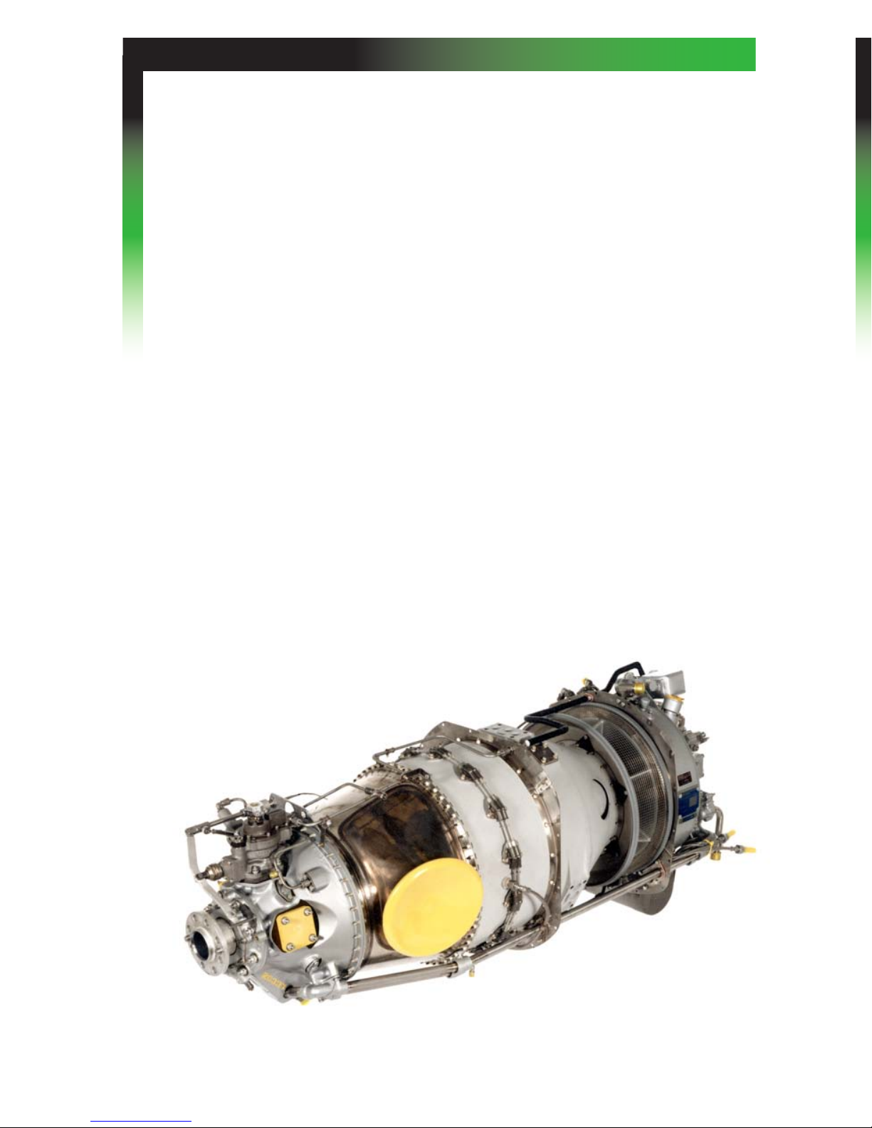
Small PT6A Engine
moDulArity
The design of the PT6A engine allows it to be split into two major parts
called the power section assembly and the gas generator assembly. Only
certain engine models are defined as being modular, which allows the
interchange and tracking of each module. Three criteria must be met for the
engine to be modular.
1. Each major assembly is equipped with a data plate and a third data
plate is located on the inlet case for the complete engine assembly.
2. There is a logbook for each module.
3. In the appropriate SB on service lives, there will be an overhaul interval
quoted for each module and the engine assembly.
On non-modular PT6A engines, the power section assembly can be removed
and sent for service, but must be returned and installed on the same gas
generator assembly.
Small PT6A Engine

1212 12
ADvAntAges of the pt6A engine Design
A number of advantages are derived from the design of the PT6A engine
which have proven valuable in routine field operation.
During an engine start, only the compressor section of the PT6A engine
needs be rotated by the starter-generator. By comparison, a fixed-shaft
engine must spin all rotating components including the reduction gearbox
and propeller during an engine start, resulting in a requirement for heavier
starting systems.
The PT6A engine free turbine design allows the propeller RPM to be reduced
and the propeller feathered during ground operation without shutting
down the engine. This facilitates fast passenger loading and permits very
quiet ground operation. Propeller RPM can also be varied in flight (on most
applications) permitting propeller RPM to be set for quieter cruise and
optimum efficiency.

1313 13
principles of operAtion
The PT6A engine consists of two main sections, the gas generator section
and the power section.
The gas generator section compresses and delivers air to the combustion
chamber where it is mixed with fuel and ignited. The resulting hot gases
turn the compressor turbine which provides the power to run the compressor
and the accessory gearbox located at the rear of the engine. The hot gases
continue on to the power turbine where the remaining energy is extracted to
turn the propeller.
Np Nf T5 (ITT) Ng
Wf
FCU
Tq
1414 14
Air is directed to a compressor consisting of three axial stages (Four
axial stages on large PT6A engine models) and one centrifugal stage.
Compressed air leaving the compressor passes through diffuser pipes
which turn the flow 90 degrees, reduce its speed and direct the air into the
combustion chamber.
In the annular combustion chamber the air is mixed with fuel and burned.
Two igniter plugs are used to light the fuel/air mixture when the engine is
started. They are not required to maintain the combustion process and can
be shut off once the engine has reached idle speed.
The expanding hot gases are directed first through the compressor turbine
and then through the power turbine. After passing through the power
turbine, the gases are exhausted through ports on each side of the engine.
(Some engines are fitted with a single-port exhaust.) The exhaust stubs
fitted to the engine are normally directed to utilize the remaining energy of
the gases in the form of thrust for additional aircraft propulsion.
Two bleed air systems are incorporated in the PT6A engine. Automatic bleed
air from the compressor prevents compressor stall during acceleration from
low engine speeds or deceleration from high engine speeds. For aircraft
use, air may be bled for heating or pressurizing aircraft cabins.
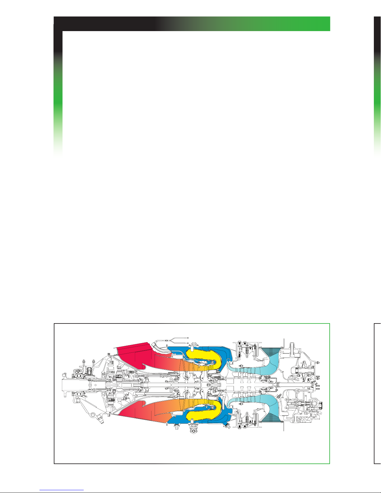
Airflow
Medium PT6A Engine
Air is directed to a compressor consisting of three axial stages (Four
axial stages on large PT6A engine models) and one centrifugal stage.
Compressed air leaving the compressor passes through diffuser pipes
which turn the flow 90 degrees, reduce its speed and direct the air into the
combustion chamber.
In the annular combustion chamber the air is mixed with fuel and burned.
Two igniter plugs are used to light the fuel/air mixture when the engine is
started. They are not required to maintain the combustion process and can
be shut off once the engine has reached idle speed.
The expanding hot gases are directed first through the compressor turbine
and then through the power turbine. After passing through the power
turbine, the gases are exhausted through ports on each side of the engine.
(Some engines are fitted with a single-port exhaust.) The exhaust stubs
fitted to the engine are normally directed to utilize the remaining energy of
the gases in the form of thrust for additional aircraft propulsion.
Two bleed air systems are incorporated in the PT6A engine. Automatic bleed
air from the compressor prevents compressor stall during acceleration from
low engine speeds or deceleration from high engine speeds. For aircraft
use, air may be bled for heating or pressurizing aircraft cabins.
Airflow
Medium PT6A Engine
1515 15
A shaft connects the power turbine to the two-stage planetary reduction
gearbox. The first stage reduction ring gear floats axially against a hydraulic
torquemeter cylinder. The oil pressure in this cylinder is proportional to
output torque which is displayed on the torque indicator in the cockpit.
Bevel gears located forward of the second stage planetary gears drive the
following accessories mounted on the forward reduction gearbox case:
·propeller governor or constant speed unit
· propeller overspeed governor
· tachometer-generator
The accessory gearbox, mounted on the rear of the engine, is used to drive
the following engine accessories:
· High-pressure fuel pump
· Fuel control unit
· Oil scavenge and oil pressure pumps.
Space is also provided for aircraft manufacturer provided accessories such
as the starter-generator, gas generator tachometer-generator, fuel boost
pumps or hydraulic pumps.
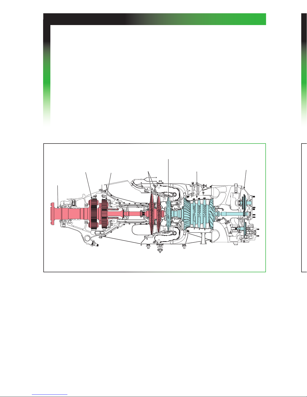
power trAin
1 ST STAGE
REDUCTION
GEAR
PROPELLER
SHAFT
2 ND STAGE
REDUCTION
GEAR
POWER
TURBINES
COMPRESSOR
TURBINE
ACCESSORY
GEARBOX
COMPRESSOR
Large PT6A Engine
A shaft connects the power turbine to the two-stage planetary reduction
gearbox. The first stage reduction ring gear floats axially against a hydraulic
torquemeter cylinder. The oil pressure in this cylinder is proportional to
output torque which is displayed on the torque indicator in the cockpit.
Bevel gears located forward of the second stage planetary gears drive the
following accessories mounted on the forward reduction gearbox case:
·propeller governor or constant speed unit
· propeller overspeed governor
· tachometer-generator
The accessory gearbox, mounted on the rear of the engine, is used to drive
the following engine accessories:
· High-pressure fuel pump
· Fuel control unit
· Oil scavenge and oil pressure pumps.
Space is also provided for aircraft manufacturer provided accessories such
as the starter-generator, gas generator tachometer-generator, fuel boost
pumps or hydraulic pumps.
power trAin
1 ST STAGE
REDUCTION
GEAR
PROPELLER
SHAFT
2 ND STAGE
REDUCTION
GEAR
POWER
TURBINES
COMPRESSOR
TURBINE
ACCESSORY
GEARBOX
COMPRESSOR
Large PT6A Engine

1616 16
Support of the main shafts in the PT6A engine is accomplished by a
combination of ball and roller bearings. Ball bearings support axial and
radial loading, while the roller bearings support only radial loads, allowing
for thermal expansion.
Propeller Shaft Power Turbine Compressor
No. 5: Roller No. 3: Roller No. 1: Ball
No. 6: Ball No. 4: Ball No. 2: Roller
No. 7: Roller**
** Smaller reduction gearboxes do not utilize a No. 7 bearing.
beArings
A-52
A-61
A-64
A-66
A-60
A-65
A-67
765
65
4321

1717 17
foD protection
Inertial Separator
The nacelle inlet of many aircraft models includes an inertial separator
provided by the aircraft manufacturer to prevent heavy particles from
entering the engine inlet. Most installations incorporate two moveable
vanes, one upstream of the engine inlet and the other blocking the bypass
duct. For bypass operation, the inlet vane is lowered and the bypass
duct vane is opened permitting maximum separating efficiency. In some
installations, the vanes are fixed in the bypass mode.
As shown in the sketch, air entering the engine inlet must turn sharply past
the inlet vane (shown in the lowered position). Particles heavier than air
are carried straight through, by their own inertia, into the bypass duct and
dumped overboard.
The aft radial inlet design provides many advantages such as superior
anti-icing utilizing the principle of inertial separation, low noise levels and
unequalled protection from FOD.
BYPASS (ICING)
POSITION
NORMAL
POSITION

1818 18
The fuel system is designed to deliver clean fuel to the engine at the
pressure and flow that are necessary for all engine operating conditions.
The airframe fuel system contains the necessary boost pumps, transfer
pumps, selector/shutoff valves, strainers and filters required to supply fuel
to the engine(s) and to manage the fuel load distribution in the airplane.
The engine is equipped with a fuel system which consists of a fuel heater,
high-pressure fuel pump, fuel filter, fuel control unit, start control or flow
divider unit and a manifold with fuel injection nozzles.
The fuel control unit is either a hydro-pneumatic or a hydro-mechanical
system which meters the correct amount of fuel to the engine to maintain
the gas generator speed selected by the pilot via the power control lever. It
also controls fuel flow scheduling during engine starting, acceleration and
deceleration.
The PT6A engine is approved for operation with all commercial jet fuels,
JP-4, JP-5 and for a maximum of 150 hours during any overhaul period with
all grades of aviation gasoline. Specific grades of diesel fuel are approved
as alternate fuels for restricted use. No engine adjustments are required
in changing from one fuel to another, nor is it necessary to purge the fuel
system when changing fuels, except when using alternate fuels.
For listings of approved fuels and fuel additives refer to the appropriate
Service Bulletins for each PT6A engine model.
fuel system

1919 19
oil system
The PT6A engine has a self-contained oil system with the exception of the
oil cooler, air duct and associated plumbing. The oil level should be verified
after engine shutdown and while the oil is still hot, using either a dipstick
or a sightglass.
For more information related to the oil system, please refer to page 29.
Table of contents
Popular Engine manuals by other brands


O.S. Speed
O.S. Speed B21 ADAM DRAKE EDITION instruction manual

ZF Marine
ZF Marine W23100 Series operating manual

Sumitomo Drive Technologies
Sumitomo Drive Technologies IB Series Maintenance manual

Kipor
Kipor KD388 Operation manual

MerCruiser
MerCruiser QSD 2.0 manual

Cobra
Cobra DG350 Original instructions


