Precision Products PLR1836 User manual

PARTS LIST FOR LAWN ROLLERS:
PLEASE DO NOT RETURN THIS MERCHANDISE TO THE STORE. CALL US AND WE
WILL TAKE CARE OF ANY PROBLEM YOU MIGHT HAVE WITH THIS PRODUCT.
Phone (800) 225 - 5891 EXT. #204
HOW TO ORDER
REPLACEMENT PARTS:
When ordering parts always
give model number, part
number and part description.
Send To: Parts Division
316 Limit Street
Lincoln, IL 62656
TIP: Many of these
hardware parts can be
purchased at your local
hardware store.
Qty
1
1
4
2
8
4
1
2
2
1
1
2
2
1
2
1
1
1
Ref
No
1
2
3
4
5
6
7
8
9
10
11
12
13
14
15
16
17
18
Parts
No
3263
1956
1646
2576
3039
1974
3264GY
3265GY
3255
3254
3256
1806
3257GY
1042
3042
3268
3266
2311
Description
Roller Body
Expansion Plug
5/8” Flat Washer
3/16” Cotter Pin
3/8” Lock Nut
3/8” x 1” Hex Head Bolt
Center Brace
Hitch Side Bar
3/8” x 2-1/4” Hex Head Bolt
3/8” x 3/8” Spacer
Clevis Pin 1/2” x 2-1/4”
3/8” x 1-1/2” Hex Head Bolt
Clevis Plate
#14 Hitch Pin Clip
1” Handle Grip
1/2” x 2-1/2” Hex Head Bolt
Handle Tube
1/2” Lock Nut
1
PLR1824 Parts List
Phone (800) 225-5891
(217) 735-1590 Ext. 204
FAX (217) 735-2435
PLR1824
PLR1836
PLR1824
Precision Pro Plastic Lawn Roller
PLR1836
3
3
4
4
6
6
5
7
9
12
8
10
5
13
5
11
14
Handle Components – PLR1824 ONLY!
2
15
16
17
15
18
Qty
1
1
4
2
8
4
1
2
2
1
1
2
2
1
Ref
No
1
2
3
4
5
6
7
8
9
10
11
12
13
14
Parts
No
3250
1956
1646
2576
3039
1974
3251GY
3252GY
3255
3254
3256
1806
3257GY
1042
Description
Roller Body
Expansion Plug
5/8” Flat Washer
3/16” Cotter Pin
3/8” Lock Nut
3/8” x 1” Hex Head Bolt
Center Brace
Hitch Side Bar
3/8” x 2-1/4” Hex Head Bolt
3/8” x 3/8” Spacer
Clevis Pin 1/2” x 2-1/4”
3/8” x 1-1/2” Hex Head Bolt
Clevis Plate
#14 Hitch Pin Clip
PLR1836 Parts List
3258
3/04
Tools Required for Assembly:
1- Pair of Pliers
2 - 9/16” Wrenches
2 - 3/4” Wrenches
Precision Products, Inc.Precision Products, Inc.
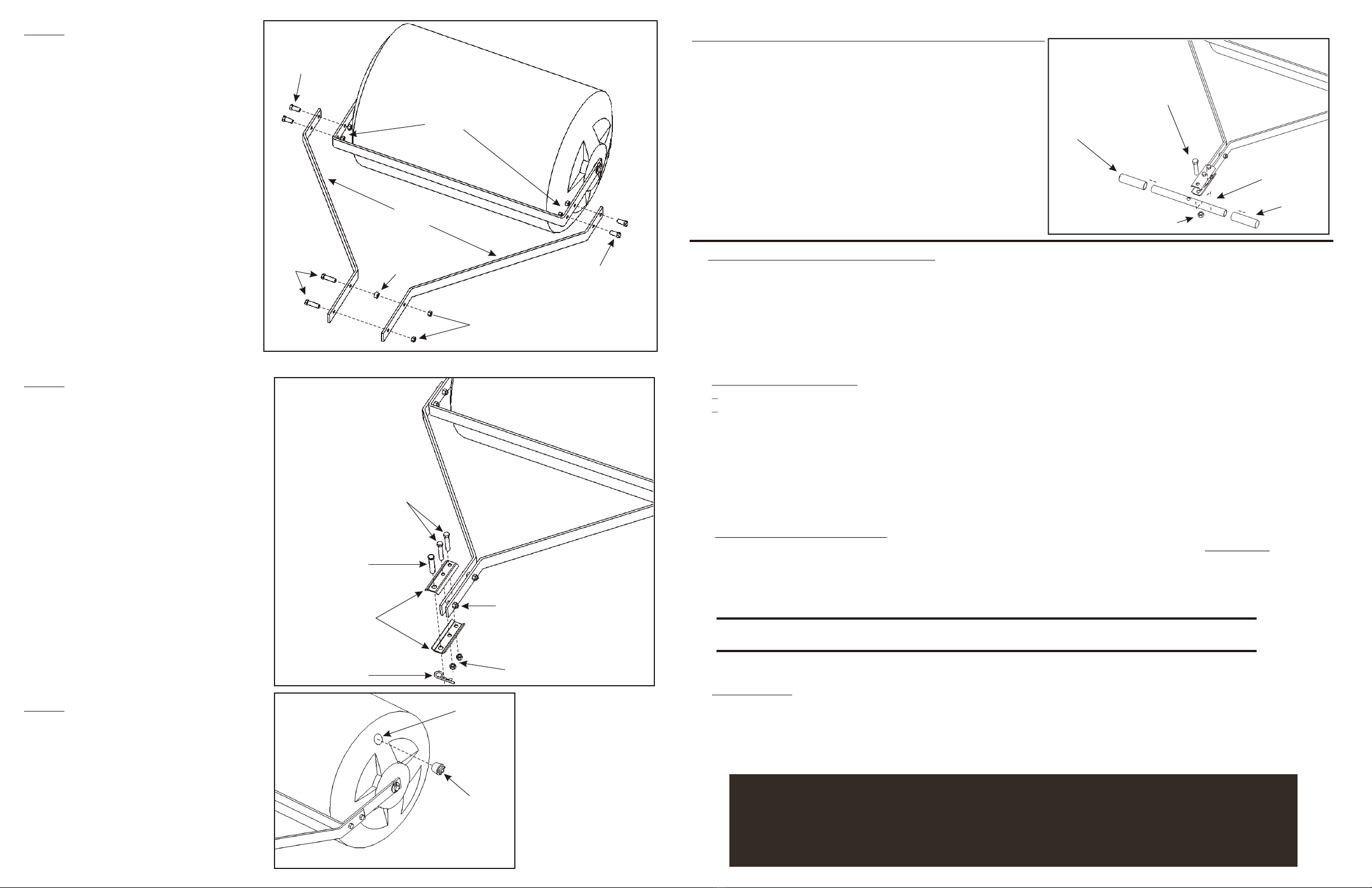
STEP 1
Place a 5/8” Flat Washer (3) over the
axle on the Roller Body (1). Do this for
both ends of the Roller Body. Fig. 1
Next, place one end of the Center Brace (7)
over one side of the axle then the opposite
side. NOTE: you will have to pull (spread out)
on one end of the Center Brace to get it to go
over the axle. Fig. 2
Place another 5/8” Flat Washer (3) over
the axle on the Roller Body (outside the
Center Brace) on each end. Fig. 1
Insert a 3/16” Cotter Pin(4) into the hole
on the axle and spread the legs of the pin
to secure into place. Repeat this procedure
for the other side of the axle. Fig. 1
Figure 1
Figure 2
3
3/16” Cotter
Pin
5/8” Flat Washers
Center
Brace
Roller Body Axle
Roller Body
Center
Brace
Pull
(spread out)
SAFETY GUIDELINES FOR USE OF PRODUCT
*The most important information is knowing how to stop your riding mower or lawn tractor, read your equipment’s owner’s manual
for horse power and towing weights
*With increased towing weight, your stopping distance increases also
*Do not tow (or push) the roller up or down steep ditches or hills. Be extremely cautious around steep grades
*Watch for holes, uneven terrain and other possible obstacles
*Inspect roller and all hardware periodically. Be sure all parts are secure before and during operation
*Never carry any passengers with you
*Do not operate lawn roller on slopes greater than 10 - 12 degrees
USING YOUR LAWN ROLLER
*Remove the expansion plug by loosening the wing nut.
*Fill your roller with water or sand to recommended weight for your towing equipment (mower or lawn tractor). DO NOT GO
OVER YOUR TOWING EQUIPMENT’S WEIGHT LIMIT. Failure to do so can result in damage to the towing equipment and/or
personal injury.
*Replace the expansion plug and tighten the wing nut. Make sure the plug is tight enough to stop any leakage.
*Your lawn should be moist for best rolling conditions. Excessive water or muddy conditions are not recommended.
*Keep your mower or lawn tractor at a safe and steady speed. 3 - 4 MPH is a good speed for proper operation.
*Damage to your mower, lawn tractor and/or personal injury can occur if you start or stop the roller (filled) abruptly.
*When finished using the roller, drain and let the interior fully dry. Never leave water in the lawn roller during cold weather. Freezing
can occur, damaging the plastic body causing leaks and/or structural failure.
MAINTENANCE
*Always check all the hardware before use. Make sure all hardware and components are tight and secure.
*Always keep moving joints lubricated. Lubricate where the Axle extends through the Hitch Side Bar when needed.
*Keeping the roller clean and dry will prolong the unit’s life.
*Sand off any rust that might occur, and paint exposed metal with a quality enamel paint.
LIMITED WARRANTY
This unit is warranted against defects in materials and workmanship to the original purchaser, under normal use and
service, for a period of ninety (90) days from date of sale. During the Warranty Period, we will repair or replace
at our option free of charge to the original purchaser, any part of the Unit that our examination shows to be defective
in workmanship or materials. This Warranty Does Not apply to damage caused by transit, misuse, abuse, neglect, accident,
normal wear, or alterations by unauthorized persons.
WEIGHT CAPACITIES PER MODEL
It is extremely important to know how much your mower or lawn equipment is designed to tow. Below are approximate weight
capacities for individual models.
Model Weight filled with water Weight filled with sand
PLR1824
PLR1836
221 lbs.
331 lbs.
353 lbs.
530 lbs
STEP 2
Attach the Hitch Side Bars (8) to the
Center Brace, using 3/8” x 1” Hex
Head Bolts (6) and 3/8” Lock Nuts (5).
Fig. 3
Insert the 3/8” x 3/8” Spacer (10) between
the two Hitch Side Bars. The Spacer needs
to be attached to the second hole back from
the front of the Hitch Side Bars. Secure the
Spacer in place by inserting a 3/8” x 1-1/2”
Hex Head Bolt (12) through one Hitch Side
Bar then the 3/8” x 3/8” Spacer and the other
Hitch Side Bar. Thread a 3/8” Lock Nut (5)
onto the bolt end. Note: Do not tighten this
bolt and nut yet. Fig. 3
Insert the other 3/8” x 1-1/2” Hex Head
Bolt (12) through the first hole on the Hitch
Side Bar. Thread a 3/8” Lock Nut (5) onto
the bolt end. Note: Do not tighten this bolt
and nut yet. Fig 3.
Figure 3
STEP 3
Attach the two Clevis Plates (13) to the end
of the Hitch Side Bars using 3/8” x 2-1/4”
Hex Head Bolts (9) and 3/8” Lock Nuts (5).
The bolts for the Clevis Plates “straddle”
(one bolt on each side) of the first
3/8” x 1-1/2” Hex Head Bolt on the end of
the Hitch Side Bar. This keeps the Clevis Plate
assembly from slipping off the Hitch Side Bars
when the unit is in use. Fig.4
Now tighten the four 3/8” Hex Head Bolts
(3/8” x 1-1/2” from STEP 2 and the
3/8” x 2-1/4” from the above procedure)
and 3/8” Lock Nuts. Fig. 4
Insert the Clevis Pin (11) through the hole
on the Clevis Plates and secure with the
#14 Hitch Pin Clip (14) Fig. 4
Hitch Side Bars
3/8” x 1”
Hex Head Bolts
3/8” Lock Nuts
3/8” x 1-1/2
Hex Head Bolts 3/8” x 3/8”
Spacer
3/8” Lock Nuts
e r ce
C nte Bra
3/8” x 1”
Hex Head Bolts
Figure 4
Clevis
Plates
3/8” x 2-1/4”
Hex Head Bolts
3/8” Lock Nuts
Straddle this bolt with
the Clevis Plate bolts.
Clevis
Pin
#14 Hitch
Pin Clip
STEP 4
Insert the Expansion Plug (2) into the
hole on the end of the Roller Body.
Secure by turning the wing nut on
the Expansion Plug. Fig. 5
Figure 5 Hole in Roller Body
Expansion Plug
HANDLE OPTION IS ON PLR1824 ONLY
To use the handle option:
Remove the Clevis Pin and Hitch Pin Clip from the Clevis Plates.
Loosen the two 3/8” Bolts on the Clevis Plates. Place the Handle
Tube (17) in between the Clevis Plates. Insert the 1/2” x 2-1/2”
Hex Head Bolt through the top Clevis Plate, the hole in the Handle
Tube and the bottom Clevis Plate. Secure the 1/2” x 2-1/2” Bolt
with a 1/2” Lock Nut. NOTE: Do not over-tighten this bolt. It is
possible to damage the Handle Tube by over-tightening the
bolt. If the Handle Tube DOES get damaged; DO NOT USE.
Personal injury can happen.
Tighten the two Clevis Plate bolts. Place the 1” Handle Grips (15)
over the ends of the Handle Tube.
1/2” x 2-1/2”
Hex Head Bolt
1/2” Lock Nut
Handle Tube
1” Handle
Grip
1” Handle
Grip
This manual suits for next models
1
Popular Lawn And Garden Equipment manuals by other brands

Sunforce
Sunforce SOLAR user manual

GARDEN OF EDEN
GARDEN OF EDEN 55627 user manual

Goizper Group
Goizper Group MATABI POLMINOR instruction manual

Rain Bird
Rain Bird 11000 Series Operation & maintenance manual

Cub Cadet
Cub Cadet BB 230 brochure

EXTOL PREMIUM
EXTOL PREMIUM 8891590 Translation of the original user manual


Vertex
Vertex 1/3 HP Maintenance instructions

GHE
GHE AeroFlo 80 manual

Land Pride
Land Pride Post Hole Diggers HD25 Operator's manual

Yazoo/Kees
Yazoo/Kees Z9 Commercial Collection System Z9A Operator's & parts manual

Premier designs
Premier designs WindGarden 26829 Assembly instructions

Snapper
Snapper 1691351 installation instructions