Precision Products SW38PRE User manual

SW38PRE - 38” Tow Behind Lawn Sweeper
Owner’s Manual and Parts List
Precision Products, Inc.
2
1
3
4
6
7
5
8
9
5
10
11
12
13
16
15
14
17
1818
19
20 21
22
28
26
27
25
24
23
30
29
Parts List for SW38PRE
31
32
5
33
36
38
37
39
41
40
43
42
44
45
46
23
35
47
48
49
1
2
3
4
5
6
7
8
9
10
11
12
13
14
15
16
17
18
19
20
21
22
23
24
25
26
27
28
29
30
31
32
33
34
35
36
37
38
39
40
41
42
43
44
45
46
47
48
49
50
**
**
**
**
Height Adjustment Tube
Handle Grip
Caster Assembly
Sweeper Chassis
5/16” Lock Nut
5/16” x 2” Hex Head Bolt
Bumper Assembly
Hitch Arms
5/16” x 2 1/4” Hex Head Bolt
Clevis Plate
5/16” x 3-1/4” Hex Head Bolt
Hamper Pivot Bracket Assembly
Top Hamper Cross Tube
Bottom Hamper Cross Tube
Hamper Support Rod
Bottom Hamper Side Tube
Top Side Hamper Tube
Tie Rod
5/16” x 5/8” Hex Head Bolt
1/4” x 1-3/4” Hex Head Bolt
5/16” x 3/4” Hex Head Bolt
1/4” x 1/2” Hex Head Bolt
5/16” x 1/2” Hex Head Bolt
Wheel Shield
Stub Axle
Pinion Gear
10” Tire
10” Die Cast Wheel
5/8” E Type Snap Ring
Plastic Hub Cap
Flange Bearing
3/8” Lock Nut
Pinion Pawl
3/8” Pilot Nut
RH Hamper Pivot Bracket
Top Pivot Cross Tube
1/4” x 1-1/2” Hex Head Bolt
LH Hamper Pivot Bracket
LH Cross Tube Lock
1/4” Lock Nut
RH Cross Tube Lock
Plastic Hamper Hinge
Vertical Pivot Tube
Pivot Support Tube
Pivot Stand Tube
Pivot Stand Brace
Brush Strip
Brush Spring
Bush/Axle/Disc Assembly
Catch Bracket
**PARTS NOT ILLUSTRATED
Hamper (Material)
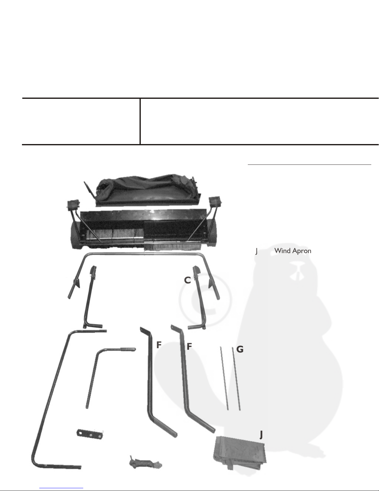
Wind Apron
Hamper Dump Rope
Spring
20
Ref # Part Description Qty.
34
Part # Ref # Part Description Qty.
Part #
LIMITED WARRANTY
This unit is warranted against defects in materials and workmanship to the original
purchaser, under normal use and service, for a period of ninety (90) days from date
of sale. During the Warranty Period, we will repair or replace at our option free of
charge to the original purchaser, any part of the Unit that our examination shows to
be defective in workmanship or materials. This Warranty Does Not apply to damage
caused by misuse, abuse, neglect, accident, normal wear, or alterations by
unauthorized persons.
Customer Service & Warranty Information
PLEASE DO NOT RETURN THIS MERCHANDISE TO THE STORE. CALL US AND WE WILL TAKE CARE OF ANY
PROBLEM YOU MIGHT HAVE WITH THIS PRODUCT. Phone (800) 225 - 5891 EXT. #204
When ordering parts always give model
number, part description & part number.
Send To: Precision Products, Inc.
Parts Division Phone (217) 735-1590
316 Limit Street Fax (217) 735-2435
Lincoln, IL 62656
Parts list on back page
1
1
2
1
19
1
1
2
2
2
1
2
1
1
2
2
2
1
4
2
2
2
8
2
2
2
2
2
2
2
2
2
2
2
1
1
3
1
1
13
1
2
2
2
2
2
6
18
1
1
1
1
1
1
01/04
1745
1746
1747
3230
1749
4041
3231
3232
1752
1753
1754
1755
3233
3234
1758
1792
1759
3235
1761
1065
1248
1647
1762
1763
1764
1765
1766
1767
1768
1769
1770
1771
1772
1773
1774
3236
6129
1776
1777
1778
1779
1780
1781
1782
1783
1784
3237
1786
3238
1795
3239
3240
1790
1282
37
40
50
Your new SW38PRE lawn sweeper is precision manufactured using the finest in tools and materials. Although it is
ruggedly constructed, do not subject this unit to misuse. Be sure to wipe off your unit after each use. Store in a
dry place out of direct sunlight. Do not permit the lawn sweeper to stand in the hot sun, unless it is in actual use.
You will find many work saving uses for your lawn sweeper. Use it early in the spring to give your lawn a good healthy
scrubbing. Use it throughout spring and summer before and after mowing. Sweeping your lawn before mowing stands
the grass up for a clean, even cut. It also allows increased protection to your mower by removing sticks, stones and
nuts, which might damage the blade(s) on your mower. Sweeping your lawn after mowing will whisk away unsightly
grass clippings - leaving your lawn velvety smooth.
Tools Required For Assembly:
Assembly Parts List Description
One (1) - Pair Pliers (Needle Nose)
Two (2) - 7/16” Wrenches
Two (2) - ½” Wrenches
Prior To Assembly:
Remove all Sweeper Parts from carton. Make sure all parts and assemblies are
present before assembly. If any parts are missing, contact Customer Service
(contact information on back sheet) immediately for assistance.
Lay out all parts and have tools ready.
Hamper Assembly
Chassis Assembly
Pivot Frame Assembly
Bottom Hamper Cross Tube
Height Adjustment Tube
Hitch Arms
Hamper Support Rods
Clevis Plates
Hamper Dump Rope
Wind Apron
1
1
1
1
1
2
2
2
1
1
Ref. Description Qty.
Parts List Of SW38PRE
A
B
C
D
E
FG
H
I
J
A
B
C
D
E
F
G
H
I
J
Ref.
F
CC
OPERATION:
Brush Adjustment: Your new trailer-sweeper is
equipped with a handy, “From Your Seat” brush
adjustment. To raise, push Height Adjustment Tube
back and down until desired sweeping height is
attained. To lower, push Height Adjustment Tube
back and pull up to desired sweeping height (See Fig 18).
For best results, brushes should barely touch the top
of the grass blades. Brushes should be raised when
transporting the unit to and from sweeping area.
Sweeping Speed: For best results, rider/tractor
should travel at a 3 to 5 M.P.H. range.
Dumping: Simply pull the Hamper Dump Rope
forward to empty debris (See Fig. 19). Slowly ease
the Hamper Dump Rope back, keeping even
pressure, until the Hamper returns back down.
CAUTION: DO NOT ALLOW THE HAMPER DUMP
ROPE TO HAVE TOO MUCH SLACK IN IT WHEN
OPERATING. THE ROPE CAN GET CAUGHT IN
THE BRUSHES CAUSING INJURIES.
Pull Hamper
Dump Rope
Low
High
Fig. 18
Fig. 19
Height
Adjustment
Tube
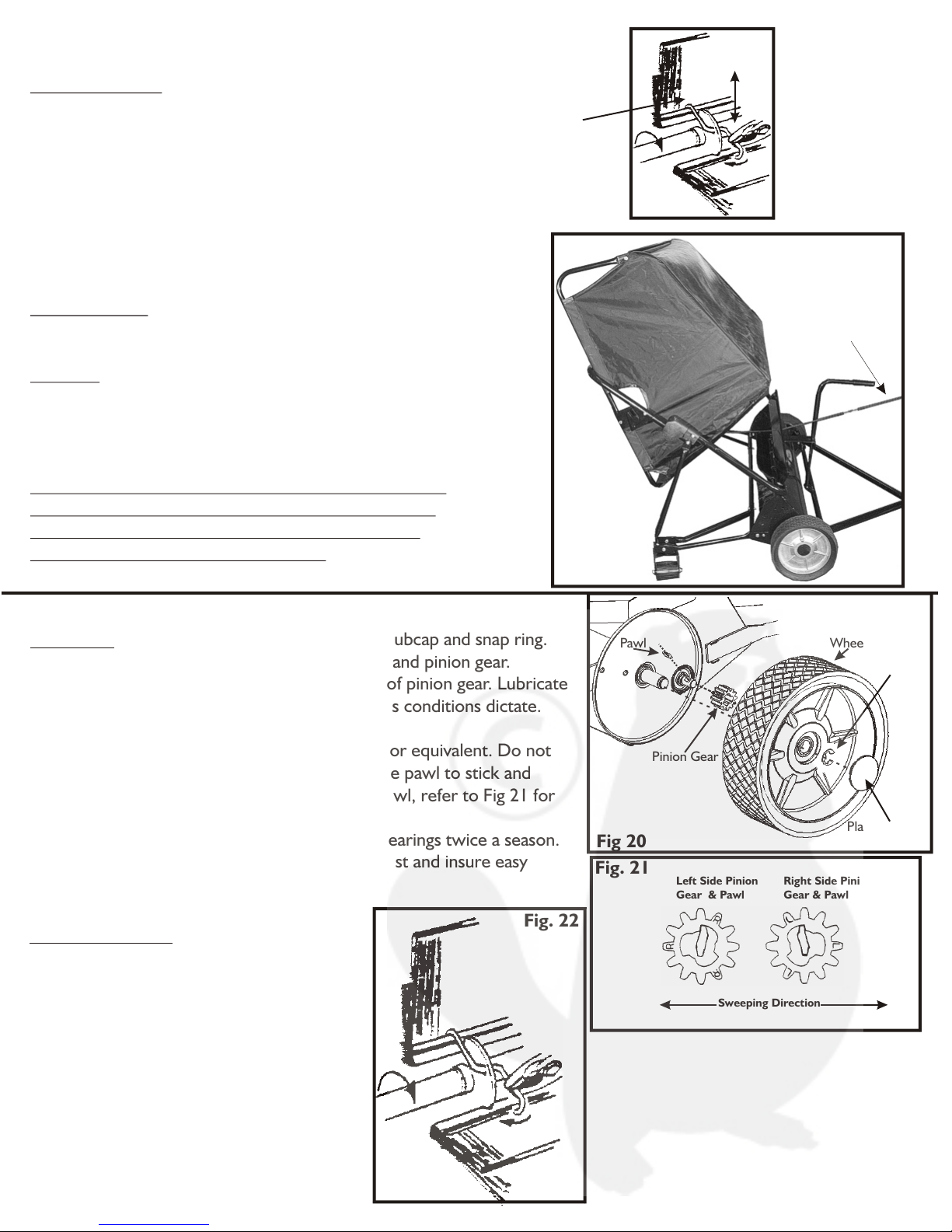
MAINTENANCE:
Lubrication: Remove wheel by removing plastic hubcap and snap ring.
Apply a light multipurpose grease to wheel gear and pinion gear.
NOTE: DO NOT allow grease to enter center of pinion gear. Lubricate
at the beginning of each season or more often as conditions dictate.
See Fig. 20.
Remove pinion gear and oil pawl with SAE #20 or equivalent. Do not
apply grease or heavy oil to pawl. This causes the pawl to stick and
operate erratically. When installing pinion and pawl, refer to Fig 21 for
correct position.
Apply SAE #20 oil or equivalent to brush axle bearings twice a season.
Oil Hamper pivot pins occasionally to prevent rust and insure easy
dumping.
Fig 20 Plastic Hubcap
Wheel
Snap Ring
Pinion Gear
Pawl
Sweeping Direction
Left Side Pinion
Gear & Pawl
Right Side Pinion
Gear & Pawl
Fig. 21
Brush Replacement:
Place brush strips in slots of brush disc so
shorter supporting bristles are away from
brush sweeping rotation. Secure at each
disc with three holder springs. Feed spring
through hole in disc. Place upper point into
bristles with point next to disc. With pliers,
grasp springs, turn and raise upward so lower
point is secured on backing of second brush.
Tap each end of spring with pliers to make
certain that the points are completely down
into bristles. See Fig. 22
Fig. 22

Step 1
Attach the Pivot Stand Brace (pre-attached to Sweeper Chassis)
to the Sweeper Chassis using a 1/4” x 1-1/4” Bolt. Repeat this step
for the other Pivot Stand Brace. Fig. 1
Lock the Pivot Stand Tube in place by inserting a 1/4” x 1/2”
Bolt through the Pivot Stand Tube and Sweeper Assembly and
securing it with a 1/4” Lock Nut. Fig.1
Tighten the nut on the pre-attached 5/16” Bolt if needed. Pivot Stand
Brace
Sweeper
Chassis
1/4 x 1-1/4”
Bolt
Step 2
Attach both Bottom Pivot Frame Assemblies to both right and left
sides on the front of the Sweeper Chassis using two 1/4” x 1-1/2”
Hex Head Bolts and two 1/4” Lock Nuts. Fig.2 (Right Bottom Pivot
Frame Assembly Shown) Next, bolt the Vertical Pivot Tube on the
Pivot Frame Assembly to the Caster Assembly using two
5/16” x 1/2” Bolts and two 5/16” Lock Nuts. Fig.2
Remove the bottom 1/4” x 1-1/2” Bolts (on both Bottom Pivot Frame
Assemblies, Fig. 3) and insert the Top Pivot Frame Assembly into both sides. Fig.4
The tube ends will attach inside the Plastic Hamper Hinge. Re-insert
the removed 1/4” x 1-1/2” Bolts to secure the Top Pivot Frame Assembly.
Attach the Catch Bracket on top of the Top Pivot Frame Assembly Tube
using the (pre-attached) 1/4” x 1-1/2” Bolt and 1/4” Lock Nut. Fig 5
Top Pivot Frame Assembly
Sweeper Chassis
Pivot Frame Brackets
under the Pivot Frame
Assembly and gaps
opening towards the
rear of the unit
Caster
Assembly
Vertical
Pivot
Tube
5/16” x 1/2”
Bolt
Step 7
Insert the Hamper Dump Rope through
center hole on the Sweeper Chassis Assembly.
Next, lay the Hamper Dump Rope behind the
sweeper. Fig. 15
Loosen the bolts holding both right and left
Hamper Pivot Bracket Assemblies. Fig. 14
Install the Hamper Assembly onto the Pivot Frame
Assembly. The Hamper Pivot Bracket Assemblies
fit inside the slots on both Frame Pivot Brackets.
Tighten both bolts after Hamper installation. Fig. 16
The Hamper Dump Rope needs to go under
and up the back side of the Hamper Assembly
for proper dumping operation. Tie the Hamper
Dump Rope end to the center of the Top Hamper
Cross Brace. Fig. 17
Hamper Dump
Rope
Hamper Pivot
Bracket & Bolt
Hamper Dump
Rope
Top Hamper
Cross Tube
STORAGE:
Remove both Hamper Support Rods
on the inside of the Hamper.
Next, simply release both Cross Tube
Locks and fold the Hamper down.
You can also pull the Hitch
Arm Assembly up and tie
it off through the Clevis
Plates with the Hamper
Dump Rope.
Cross Tube Lock
1/4” x 1-1/2”
Bolt
1/4” x 1/2”
Bolt
Pivot Stand
Tube
NOTE: ALL REFERENCES TO “RIGHT” AND “LEFT” DIRECTIONS
ARE IN REFERENCE TO POSITION BEHIND SWEEPER.
Pre-Attached
5/16” Bolt
Fig. 1
Fig. 2
Sweeper Chassis
Fig. 3
Fig. 15
Fig. 16
Fig. 17
Vertical
Pivot
Tube
1/4” x 1-1/2”
Bolt
Right-Bottom Pivot
Frame Assembly
Top Pivot Frame
Assembly Tube
Right-Bottom
Pivot Frame Assembly
Left-Bottom
Pivot Frame Assembly
Catch Bracket
1/4” x 1-1/2” Bolt
1/4” Lock Nut
Plastic Hamper
Hinge
Plastic Hamper
Hinge
Bolt, inside
to out
1/4” Lock Nut
Fig. 4
Fig. 5
Step 4
Attach the hitch arm assembly to the front of the
Sweeper Chassis Assembly using two 5/16” x 3/4”
Hex Head Bolts and two 5/16” Lock Nuts. Fig. 8
If you have trouble attaching the Hitch Arm Assembly,
try loosening the 5/16” x 3-1/4” Hex Head Bolt in order
for the Hitch Arms to spread apart easier.
Sweeper
Chassis
Assembly
Hitch Arm
Assembly
5/16” x 3/4”
Hex Head Bolt
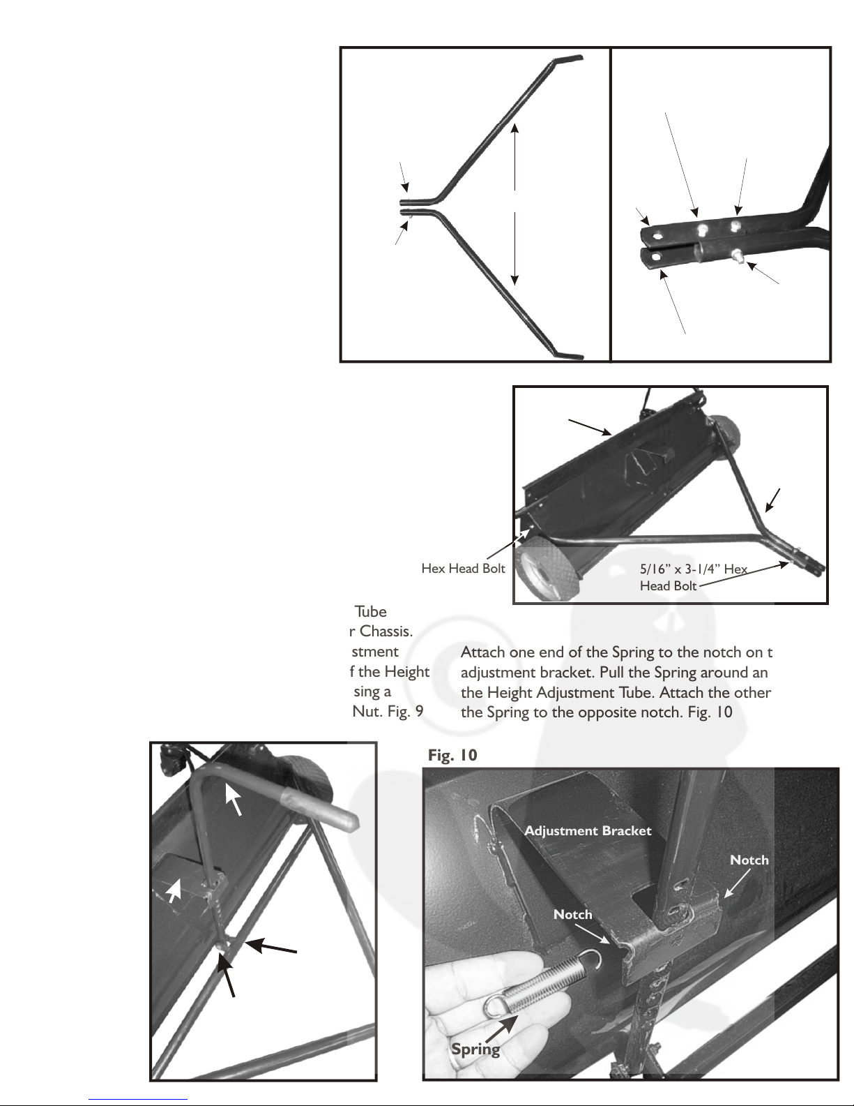
Step 5
Insert the bottom of the Height Adjustment Tube
through the hole in the front of the Sweeper Chassis.
Be sure the Handle Grip on the Height Adjustment
Tube is facing forward. Attach the bottom of the Height
Adjustment Tube to the Bumper Assembly using a
5/16” x 2” Hex Head Bolt and a 5/16” Lock Nut. Fig. 9
Height
Adjustment
Tube
Bumper
Assembly
5/16” x 2”
Hex Head Bolt
Height
Adjustment
Bracket
Notch
Spring
Step 6
For Packaging purposes the Top Side Hamper
Tubes (2 - one each side) are put on upside-down.
Remove the nut on each end of the Tie Rod and
re-attach the Top Side Hamper Tubes as shown
in illustration. Fig. 11
Insert The Top Side Hamper Tube into the
end of the Top Hamper Cross Tube. There is
a spring button lock on the Top Side Hamper
Tube that will secure these two tube assemblies
together. Fig. 11
Top Side Hamper Tube
Assembled Correctly
Tie Rod
Attach these
two tube
assemblies
together
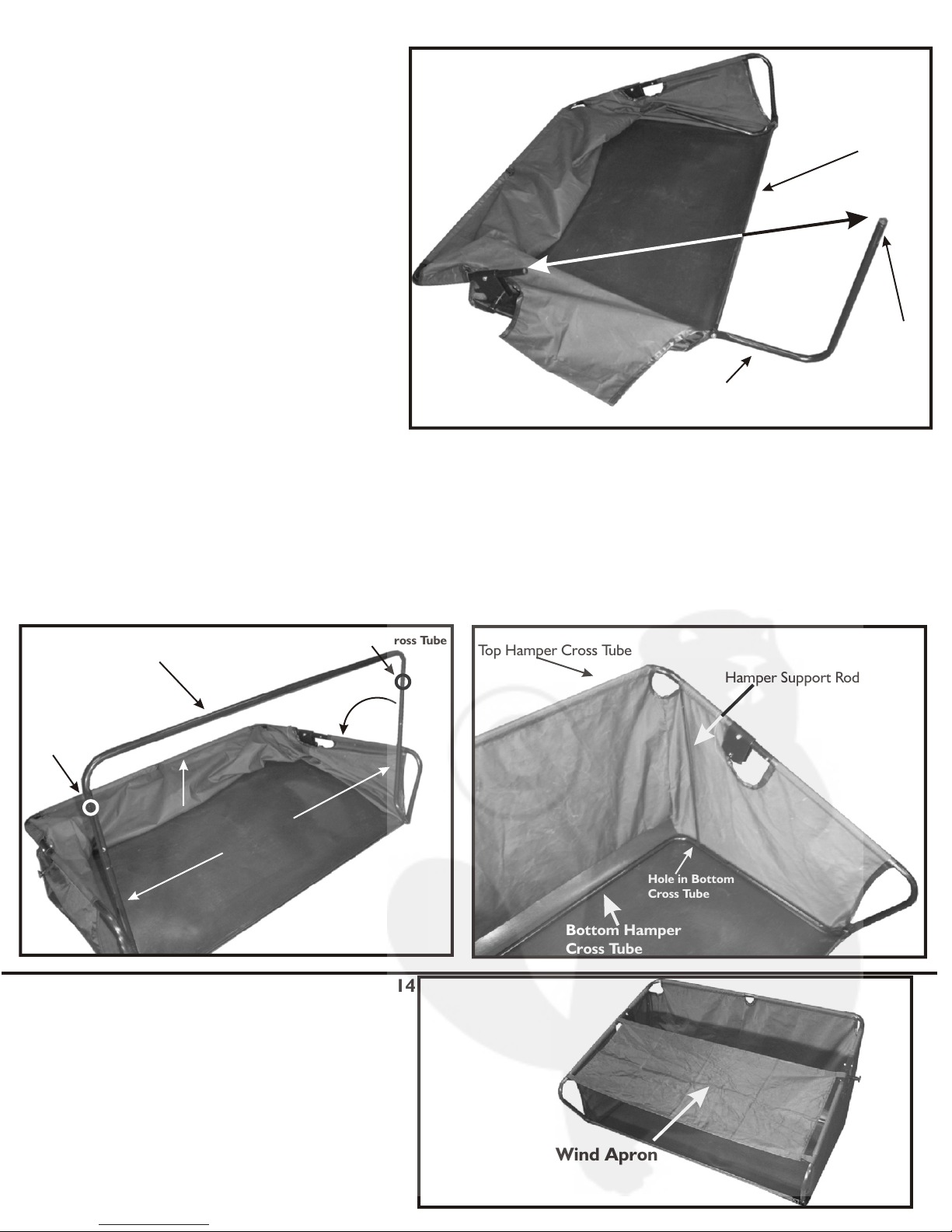
Attach the Bottom Hamper Cross Tube to the
two (one each side) Bottom Side Hamper Tubes.
The two holes in the Bottom Hamper Cross
Tube need to face out as shown in the illustration.
Fig. 12 These holes are for the Hamper Support
Rods, attached later in this assembly.
Push the Bottom Hamper Cross Tube down while
pulling up on the Top Hamper Cross Tube, this
creates the extended Hamper Assembly. Fig. 12
Finally, insert one end of the Hamper Support Rod
into the Top Hamper Cross Tube hole and the
other end of the Hamper Support Rod into the Bottom
Hamper Cross Tube hole. Fig. 13 Repeat this process for
the other Hamper Support Rod on the other side of
the Hamper Assembly.
Bottom Hamper Cross Tube
Side Hamper
Tubes
Top Hamper Cross Tube
Bottom Hamper
Cross Tube
Hamper Support Rod
Attach the optional Wind Apron to the
outside tubes towards the front of the
Hamper Assembly. Fig. 14
The Wind Apron helps keep debris from
blowing out of the Hamper Assembly while
the unit is in use.
Wind Apron
5/16” x 3-1/4” Hex
Head Bolt
Fig. 8
Fig. 9
Fig. 10
Notch
Adjustment Bracket
Fig. 11
Spring
Button
Lock
Fig. 12
Hole in Bottom
Cross Tube
Hole in Bottom Cross Tube
Push
Down
lPu l Up
Hole in Bottom
Cross Tube
Fig. 13
Fig. 14
Attach one end of the Spring to the notch on the height
adjustment bracket. Pull the Spring around and behind
the Height Adjustment Tube. Attach the other end of
the Spring to the opposite notch. Fig. 10
Step 3
Attach both Hitch Arms together using
one 5/16” x 3-1/4” Hex Head Bolt and
one 5/16” Lock Nut. Fig. 6 Do not tighten
this bolt yet.
Attach both Clevis Plates to the end of
the Hitch Arms. One 5/16” x 2-1/4”
Hex Head Bolt is attached in front
of the 5/16” x 3-1/4” Hex Head Bolt that
was used to connect the Hitch Arms.
The other 5/16” x 2-1/4” Hex Head Bolt
needs to be behind the Hitch Arm Bolt.
Tighten the Hitch Arm bolt then the two
Clevis Plate Bolts. Fig. 7 This arrangement
keeps the Clevis Plates from slipping off
the end of the Hitch Arms while in use.
Hitch Arms
5/16” x 3-1/4”
Hex Head Bolt
5/16” Lock Nut
Clevis Plate
5/16” x 3-1/4”
Hitch Arm
Bolt
Clevis Plate
FRONT 5/16” x 2-1/4”
Hex Head Bolt
BACK 5/16” x 2-1/4”
Hex Head Bolt
Fig. 6
Fig. 7
Step 4
Attach the hitch arm assembly to the front of the
Sweeper Chassis Assembly using two 5/16” x 3/4”
Hex Head Bolts and two 5/16” Lock Nuts. Fig. 8
If you have trouble attaching the Hitch Arm Assembly,
try loosening the 5/16” x 3-1/4” Hex Head Bolt in order
for the Hitch Arms to spread apart easier.
Sweeper
Chassis
Assembly
Hitch Arm
Assembly
5/16” x 3/4”
Hex Head Bolt
Step 5
Insert the bottom of the Height Adjustment Tube
through the hole in the front of the Sweeper Chassis.
Be sure the Handle Grip on the Height Adjustment
Tube is facing forward. Attach the bottom of the Height
Adjustment Tube to the Bumper Assembly using a
5/16” x 2” Hex Head Bolt and a 5/16” Lock Nut. Fig. 9
Height
Adjustment
Tube
Bumper
Assembly
5/16” x 2”
Hex Head Bolt
Height
Adjustment
Bracket
Notch
Spring
Step 6
For Packaging purposes the Top Side Hamper
Tubes (2 - one each side) are put on upside-down.
Remove the nut on each end of the Tie Rod and
re-attach the Top Side Hamper Tubes as shown
in illustration. Fig. 11
Insert The Top Side Hamper Tube into the
end of the Top Hamper Cross Tube. There is
a spring button lock on the Top Side Hamper
Tube that will secure these two tube assemblies
together. Fig. 11
Top Side Hamper Tube
Assembled Correctly
Tie Rod
Attach these
two tube
assemblies
together
Attach the Bottom Hamper Cross Tube to the
two (one each side) Bottom Side Hamper Tubes.
The two holes in the Bottom Hamper Cross
Tube need to face out as shown in the illustration.
Fig. 12 These holes are for the Hamper Support
Rods, attached later in this assembly.
Push the Bottom Hamper Cross Tube down while
pulling up on the Top Hamper Cross Tube, this
creates the extended Hamper Assembly. Fig. 12
Finally, insert one end of the Hamper Support Rod
into the Top Hamper Cross Tube hole and the
other end of the Hamper Support Rod into the Bottom
Hamper Cross Tube hole. Fig. 13 Repeat this process for
the other Hamper Support Rod on the other side of
the Hamper Assembly.
Bottom Hamper Cross Tube
Side Hamper
Tubes
Top Hamper Cross Tube
Bottom Hamper
Cross Tube
Hamper Support Rod
Attach the optional Wind Apron to the
outside tubes towards the front of the
Hamper Assembly. Fig. 14
The Wind Apron helps keep debris from
blowing out of the Hamper Assembly while
the unit is in use.
Wind Apron
5/16” x 3-1/4” Hex
Head Bolt
Fig. 8
Fig. 9
Fig. 10
Notch
Adjustment Bracket
Fig. 11
Spring
Button
Lock
Fig. 12
Hole in Bottom
Cross Tube
Hole in Bottom Cross Tube
Push
Down
lPu l Up
Hole in Bottom
Cross Tube
Fig. 13
Fig. 14
Attach one end of the Spring to the notch on the height
adjustment bracket. Pull the Spring around and behind
the Height Adjustment Tube. Attach the other end of
the Spring to the opposite notch. Fig. 10
Step 3
Attach both Hitch Arms together using
one 5/16” x 3-1/4” Hex Head Bolt and
one 5/16” Lock Nut. Fig. 6 Do not tighten
this bolt yet.
Attach both Clevis Plates to the end of
the Hitch Arms. One 5/16” x 2-1/4”
Hex Head Bolt is attached in front
of the 5/16” x 3-1/4” Hex Head Bolt that
was used to connect the Hitch Arms.
The other 5/16” x 2-1/4” Hex Head Bolt
needs to be behind the Hitch Arm Bolt.
Tighten the Hitch Arm bolt then the two
Clevis Plate Bolts. Fig. 7 This arrangement
keeps the Clevis Plates from slipping off
the end of the Hitch Arms while in use.
Hitch Arms
5/16” x 3-1/4”
Hex Head Bolt
5/16” Lock Nut
Clevis Plate
5/16” x 3-1/4”
Hitch Arm
Bolt
Clevis Plate
FRONT 5/16” x 2-1/4”
Hex Head Bolt
BACK 5/16” x 2-1/4”
Hex Head Bolt
Fig. 6
Fig. 7

Step 1
Attach the Pivot Stand Brace (pre-attached to Sweeper Chassis)
to the Sweeper Chassis using a 1/4” x 1-1/4” Bolt. Repeat this step
for the other Pivot Stand Brace. Fig. 1
Lock the Pivot Stand Tube in place by inserting a 1/4” x 1/2”
Bolt through the Pivot Stand Tube and Sweeper Assembly and
securing it with a 1/4” Lock Nut. Fig.1
Tighten the nut on the pre-attached 5/16” Bolt if needed. Pivot Stand
Brace
Sweeper
Chassis
1/4 x 1-1/4”
Bolt
Step 2
Attach both Bottom Pivot Frame Assemblies to both right and left
sides on the front of the Sweeper Chassis using two 1/4” x 1-1/2”
Hex Head Bolts and two 1/4” Lock Nuts. Fig.2 (Right Bottom Pivot
Frame Assembly Shown) Next, bolt the Vertical Pivot Tube on the
Pivot Frame Assembly to the Caster Assembly using two
5/16” x 1/2” Bolts and two 5/16” Lock Nuts. Fig.2
Remove the bottom 1/4” x 1-1/2” Bolts (on both Bottom Pivot Frame
Assemblies, Fig. 3) and insert the Top Pivot Frame Assembly into both sides. Fig.4
The tube ends will attach inside the Plastic Hamper Hinge. Re-insert
the removed 1/4” x 1-1/2” Bolts to secure the Top Pivot Frame Assembly.
Attach the Catch Bracket on top of the Top Pivot Frame Assembly Tube
using the (pre-attached) 1/4” x 1-1/2” Bolt and 1/4” Lock Nut. Fig 5
Top Pivot Frame Assembly
Sweeper Chassis
Pivot Frame Brackets
under the Pivot Frame
Assembly and gaps
opening towards the
rear of the unit
Caster
Assembly
Vertical
Pivot
Tube
5/16” x 1/2”
Bolt
Step 7
Insert the Hamper Dump Rope through
center hole on the Sweeper Chassis Assembly.
Next, lay the Hamper Dump Rope behind the
sweeper. Fig. 15
Loosen the bolts holding both right and left
Hamper Pivot Bracket Assemblies. Fig. 14
Install the Hamper Assembly onto the Pivot Frame
Assembly. The Hamper Pivot Bracket Assemblies
fit inside the slots on both Frame Pivot Brackets.
Tighten both bolts after Hamper installation. Fig. 16
The Hamper Dump Rope needs to go under
and up the back side of the Hamper Assembly
for proper dumping operation. Tie the Hamper
Dump Rope end to the center of the Top Hamper
Cross Brace. Fig. 17
Hamper Dump
Rope
Hamper Pivot
Bracket & Bolt
Hamper Dump
Rope
Top Hamper
Cross Tube
STORAGE:
Remove both Hamper Support Rods
on the inside of the Hamper.
Next, simply release both Cross Tube
Locks and fold the Hamper down.
You can also pull the Hitch
Arm Assembly up and tie
it off through the Clevis
Plates with the Hamper
Dump Rope.
Cross Tube Lock
1/4” x 1-1/2”
Bolt
1/4” x 1/2”
Bolt
Pivot Stand
Tube
NOTE: ALL REFERENCES TO “RIGHT” AND “LEFT” DIRECTIONS
ARE IN REFERENCE TO POSITION BEHIND SWEEPER.
Pre-Attached
5/16” Bolt
Fig. 1
Fig. 2
Sweeper Chassis
Fig. 3
Fig. 15
Fig. 16
Fig. 17
Vertical
Pivot
Tube
1/4” x 1-1/2”
Bolt
Right-Bottom Pivot
Frame Assembly
Top Pivot Frame
Assembly Tube
Right-Bottom
Pivot Frame Assembly
Left-Bottom
Pivot Frame Assembly
Catch Bracket
1/4” x 1-1/2” Bolt
1/4” Lock Nut
Plastic Hamper
Hinge
Plastic Hamper
Hinge
Bolt, inside
to out
1/4” Lock Nut
Fig. 4
Fig. 5
Your new SW38PRE lawn sweeper is precision manufactured using the finest in tools and materials. Although it is
ruggedly constructed, do not subject this unit to misuse. Be sure to wipe off your unit after each use. Store in a
dry place out of direct sunlight. Do not permit the lawn sweeper to stand in the hot sun, unless it is in actual use.
You will find many work saving uses for your lawn sweeper. Use it early in the spring to give your lawn a good healthy
scrubbing. Use it throughout spring and summer before and after mowing. Sweeping your lawn before mowing stands
the grass up for a clean, even cut. It also allows increased protection to your mower by removing sticks, stones and
nuts, which might damage the blade(s) on your mower. Sweeping your lawn after mowing will whisk away unsightly
grass clippings - leaving your lawn velvety smooth.
Tools Required For Assembly:
Assembly Parts List Description
One (1) - Pair Pliers (Needle Nose)
Two (2) - 7/16” Wrenches
Two (2) - ½” Wrenches
Prior To Assembly:
Remove all Sweeper Parts from carton. Make sure all parts and assemblies are
present before assembly. If any parts are missing, contact Customer Service
(contact information on back sheet) immediately for assistance.
Lay out all parts and have tools ready.
Hamper Assembly
Chassis Assembly
Pivot Frame Assembly
Bottom Hamper Cross Tube
Height Adjustment Tube
Hitch Arms
Hamper Support Rods
Clevis Plates
Hamper Dump Rope
Wind Apron
1
1
1
1
1
2
2
2
1
1
Ref. Description Qty.
Parts List Of SW38PRE
A
B
C
D
E
FG
H
I
J
A
B
C
D
E
F
G
H
I
J
Ref.
F
CC
OPERATION:
Brush Adjustment: Your new trailer-sweeper is
equipped with a handy, “From Your Seat” brush
adjustment. To raise, push Height Adjustment Tube
back and down until desired sweeping height is
attained. To lower, push Height Adjustment Tube
back and pull up to desired sweeping height (See Fig 18).
For best results, brushes should barely touch the top
of the grass blades. Brushes should be raised when
transporting the unit to and from sweeping area.
Sweeping Speed: For best results, rider/tractor
should travel at a 3 to 5 M.P.H. range.
Dumping: Simply pull the Hamper Dump Rope
forward to empty debris (See Fig. 19). Slowly ease
the Hamper Dump Rope back, keeping even
pressure, until the Hamper returns back down.
CAUTION: DO NOT ALLOW THE HAMPER DUMP
ROPE TO HAVE TOO MUCH SLACK IN IT WHEN
OPERATING. THE ROPE CAN GET CAUGHT IN
THE BRUSHES CAUSING INJURIES.
Pull Hamper
Dump Rope
Low
High
Fig. 18
Fig. 19
Height
Adjustment
Tube
MAINTENANCE:
Lubrication: Remove wheel by removing plastic hubcap and snap ring.
Apply a light multipurpose grease to wheel gear and pinion gear.
NOTE: DO NOT allow grease to enter center of pinion gear. Lubricate
at the beginning of each season or more often as conditions dictate.
See Fig. 20.
Remove pinion gear and oil pawl with SAE #20 or equivalent. Do not
apply grease or heavy oil to pawl. This causes the pawl to stick and
operate erratically. When installing pinion and pawl, refer to Fig 21 for
correct position.
Apply SAE #20 oil or equivalent to brush axle bearings twice a season.
Oil Hamper pivot pins occasionally to prevent rust and insure easy
dumping.
Fig 20 Plastic Hubcap
Wheel
Snap Ring
Pinion Gear
Pawl
Sweeping Direction
Left Side Pinion
Gear & Pawl
Right Side Pinion
Gear & Pawl
Fig. 21
Brush Replacement:
Place brush strips in slots of brush disc so
shorter supporting bristles are away from
brush sweeping rotation. Secure at each
disc with three holder springs. Feed spring
through hole in disc. Place upper point into
bristles with point next to disc. With pliers,
grasp springs, turn and raise upward so lower
point is secured on backing of second brush.
Tap each end of spring with pliers to make
certain that the points are completely down
into bristles. See Fig. 22
Fig. 22

SW38PRE - 38” Tow Behind Lawn Sweeper
Owner’s Manual and Parts List
Precision Products, Inc.
2
1
3
4
6
7
5
8
9
5
10
11
12
13
16
15
14
17
1818
19
20 21
22
28
26
27
25
24
23
30
29
Parts List for SW38PRE
31
32
5
33
36
38
37
39
41
40
43
42
44
45
46
23
35
47
48
49
1
2
3
4
5
6
7
8
9
10
11
12
13
14
15
16
17
18
19
20
21
22
23
24
25
26
27
28
29
30
31
32
33
34
35
36
37
38
39
40
41
42
43
44
45
46
47
48
49
50
**
**
**
**
Height Adjustment Tube
Handle Grip
Caster Assembly
Sweeper Chassis
5/16” Lock Nut
5/16” x 2” Hex Head Bolt
Bumper Assembly
Hitch Arms
5/16” x 2 1/4” Hex Head Bolt
Clevis Plate
5/16” x 3-1/4” Hex Head Bolt
Hamper Pivot Bracket Assembly
Top Hamper Cross Tube
Bottom Hamper Cross Tube
Hamper Support Rod
Bottom Hamper Side Tube
Top Side Hamper Tube
Tie Rod
5/16” x 5/8” Hex Head Bolt
1/4” x 1-3/4” Hex Head Bolt
5/16” x 3/4” Hex Head Bolt
1/4” x 1/2” Hex Head Bolt
5/16” x 1/2” Hex Head Bolt
Wheel Shield
Stub Axle
Pinion Gear
10” Tire
10” Die Cast Wheel
5/8” E Type Snap Ring
Plastic Hub Cap
Flange Bearing
3/8” Lock Nut
Pinion Pawl
3/8” Pilot Nut
RH Hamper Pivot Bracket
Top Pivot Cross Tube
1/4” x 1-1/2” Hex Head Bolt
LH Hamper Pivot Bracket
LH Cross Tube Lock
1/4” Lock Nut
RH Cross Tube Lock
Plastic Hamper Hinge
Vertical Pivot Tube
Pivot Support Tube
Pivot Stand Tube
Pivot Stand Brace
Brush Strip
Brush Spring
Bush/Axle/Disc Assembly
Catch Bracket
**PARTS NOT ILLUSTRATED
Hamper (Material)
Wind Apron
Hamper Dump Rope
Spring
20
Ref # Part Description Qty.
34
Part # Ref # Part Description Qty.
Part #
LIMITED WARRANTY
This unit is warranted against defects in materials and workmanship to the original
purchaser, under normal use and service, for a period of ninety (90) days from date
of sale. During the Warranty Period, we will repair or replace at our option free of
charge to the original purchaser, any part of the Unit that our examination shows to
be defective in workmanship or materials. This Warranty Does Not apply to damage
caused by misuse, abuse, neglect, accident, normal wear, or alterations by
unauthorized persons.
Customer Service & Warranty Information
PLEASE DO NOT RETURN THIS MERCHANDISE TO THE STORE. CALL US AND WE WILL TAKE CARE OF ANY
PROBLEM YOU MIGHT HAVE WITH THIS PRODUCT. Phone (800) 225 - 5891 EXT. #204
When ordering parts always give model
number, part description & part number.
Send To: Precision Products, Inc.
Parts Division Phone (217) 735-1590
316 Limit Street Fax (217) 735-2435
Lincoln, IL 62656
Parts list on back page
1
1
2
1
19
1
1
2
2
2
1
2
1
1
2
2
2
1
4
2
2
2
8
2
2
2
2
2
2
2
2
2
2
2
1
1
3
1
1
13
1
2
2
2
2
2
6
18
1
1
1
1
1
1
01/04
1745
1746
1747
3230
1749
4041
3231
3232
1752
1753
1754
1755
3233
3234
1758
1792
1759
3235
1761
1065
1248
1647
1762
1763
1764
1765
1766
1767
1768
1769
1770
1771
1772
1773
1774
3236
6129
1776
1777
1778
1779
1780
1781
1782
1783
1784
3237
1786
3238
1795
3239
3240
1790
1282
37
40
50
Table of contents
Other Precision Products Lawn Sweeper manuals


