Precision Products TCT15 Datasheet
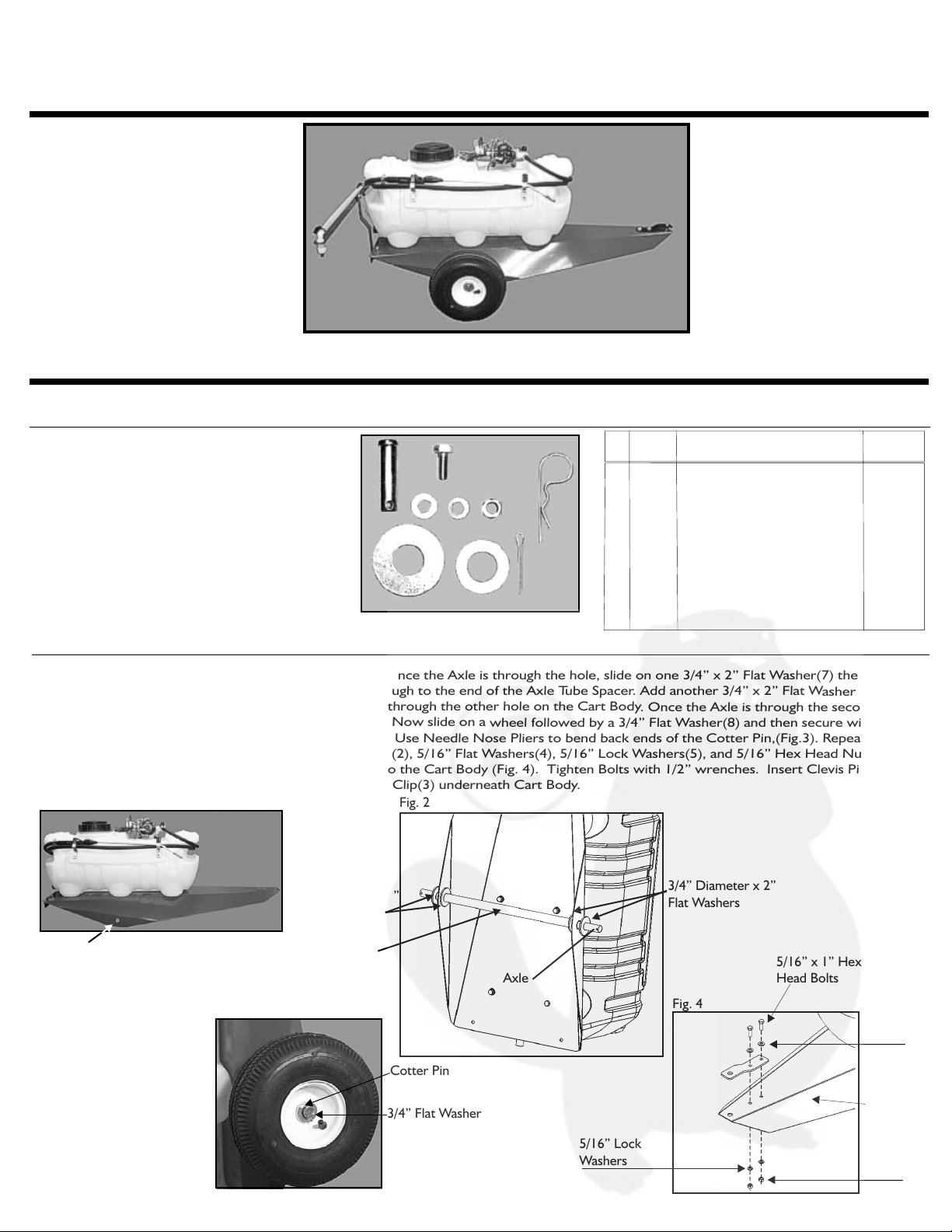
Fig. 3
3/4” Flat Washer
Cotter Pin
Axle Slot
Fig. 1
Ref.
No.
Part
No.
1 1840 1/2”x 1-3/4” Clevis Pin
2 1248 5/16” x 3/4” Hex Head Bolt
3 1042 #14 Hitch Pin Clip
4 1044 5/16” Flat Washer
5 1276 5/16” Lock Washer
6 1275 5/16” Hex Head Nut
7 3739 3/4” In Diam. x 2” Flat Washer
8 1264 3/4” Flat Washer
9 1262 1/8” x 1-1/4” Cotter Pin
1
6
1
6
6
6
4
2
2
Part Description
Hardware
Sack Qty.
Trailer Sprayer
ASSEMBLY INSTRUCTIONS & PARTS LIST 03/05
PRECISION PRODUCTS, INC.
3736-6
Assembly Hardware
Assembly Instructions
Cart Body Assembly Parts
LIMITED WARRANTY
This unit is warranted against defects in materials and workmanship to the original
purchaser, under normal use and service, for a period of ninety (90) days from date
of sale. During the Warranty Period, we will repair or replace at our option free of
charge to the original purchaser, any part of the Unit that our examination shows to
be defective in workmanship or materials. This Warranty apply to damage
caused by misuse, abuse, neglect, accident, normal wear, or alterations by
unauthorized persons.
Does Not
The electric pump on this model has its own warranty. Precision Products, Inc. does not carry
a warranty on the pump. Please refer to the parts list and operation manual for the pump
included with this model.
PRECISION PRODUCTS, INC.
Fig.3
Tools needed for assembly:
Two 1/2” Wrenches
1 Pair Needle Nose Pliers
123
5
8
9
7
6
4
Fig. 2
3/4” Diameter x 2”
Flat Washers
Axle
1/2”x 1-3/4” Clevis Pin
5/16” x 3/4” Hex Head Bolt
#14 Hitch Pin Clip
5/16” Flat Washer
5/16” Lock Washer
5/16” Hex Head Nut
3/4” Diameter x 2” Flat Washer
3/4” Flat Washer
1/8” x 1-1/4” Cotter Pin
5/16” x 1/2” Hex Head Bolt
1
2
4
42
6
3
43
44
7
10
5
8
9
2
4
45
47
5
6
5
6
62
4
5/16” Lock
Washers
Fig. 4
5/16” x 1” Hex
Head Bolts
5/16” Flat
Washers
Clevis
5/16” Hex
Head Nuts
46
STEP 1 Insert Axle through Axle Slot on Cart Body. Once the Axle is through the hole, slide on one 3/4” x 2” Flat Washer(7) then the
Axle Tube Spacer(44), then slide the Axle through to the end of the Axle T
ube Spacer. Add another 3/4” x 2” Flat Washer (inside
of the Sprayer Cart body) and push the Axle through the other hole on the Cart Body. Once the Axle is through the second hole,
slide on a 3/4” ID x 2” Flat Washer(7), (Fig.2). Now slide on a wheel followed by a 3/4” Flat Washer(8) and then secure with
a Cotter Pin(9). Repeat this for both Wheels. Use Needle Nose Pliers to bend back ends of the Cotter Pin,(Fig.3). Repeat for
other side. Using 5/16” x 3/4” Hex Head Bolts(2), 5/16” Flat Washers(4), 5/16” Lock Washers(5), and 5/16” Hex Head Nuts(6)
attach Clevis, (42),(on topside of Cart Body) to the Cart Body (Fig. 4). Tighten Bolts with 1/2” wrenches. Insert Clevis Pin(1)
through Clevis and secure with #14 Hitch Pin Clip(3) underneath Cart Body.
1
2
3
4
5
6
7
8
9
10
Ref. Part Description Part Number
Qty.
1840
1248
1042
1044
1276
1275
3739
1264
1262
1249
1
6
1
6
10
6
4
2
2
4
42
43
44
45
46
47
Ref. Part Description Part Number
Qty.
Clevis
Axle
Axle Tube Spacer
10” Pneumatic Wheel for TCT
TCT Cart Body
Boom Mount
1243P
3769
3767
3768
3740R
3766R
1
1
1
2
1
1
**Part quantities includes pieces assembled at factory
and those in hardware sack.
TCT15
TCT15RT
Cart Body
3/4” Diameter x 2”
Flat Washers
Axle Spacer
5
When ordering parts, always give model number,
part description, & part number.
Precision Products, Inc.
Parts Division (217)735-1590
316 Limit Street (217)735-2435
Lincoln, IL 62656
or visit us on the world wide web :www.precisionprodinc.com
Send To:
Phone
Fax
Customer Service
CUSTOMER SUPPORT
At Precision Products, Inc. delivering quality, value and outstanding service is our goal.
However, sometimes parts do become damaged or lost during transport from our facilities to
the store. If you have any problems, please do not return this merchandise to the store.
Call us and we will take care of any problem you may have with this unit.

Rear View
5/16” Hex Head Bolts
5/16” Flat Washer
Fig. 5
Boom Mount
Assembly Instructions Continued
Ref. Part Description Part Number
6
4
8
8
1
1
2
3
3
1
2
4
1
1
1
1
1
1
4
11
12
13
14
15
16
17
18
19
20
21
22
23
24
25
26
27
28
Part Description
Ref. Part Number Qty.
Hose Clamp .702 - .801 Plastic
10-24 x 1-1/4 Round Head Screw
#10 Flat Washer (10FWZP)
3/16” Lock Washer
Wire Harness
15 Gallon Sprayer Tank
Wand Holder
Nozzle Cap
Suction Strainer*
3/8 Rubber Hose 24”
Hose Barb 3/8 MPT x 3/8 HB
10-24 x 1/2 Bolt
Tank Lid
Pump Electric: Check Model Number
Models TCT15-12V (1.0 W/O Switch)
Models TCT15RT-12V (1.0 W/ Switch)
3/8” MPT x 1/4” MPT Nipple
Nylon Tee, 1/4”
1/4 MPT x 3/8 HB
1/2” Stainless Steel Clamp
3716
3604
3605
2987
3732
3614
3612
3620
3619
3777
3607
3613
3601
3655
3656
3728
3718
3731
3632
Qty.
29
30
31
32
33
34
35
36
37
38
39
40
41
3/8 Rubber Hose 12’
Spray Wand & Nozzle
1/4 MPT x 1/4 FPT Valve
1/4 MPT x 1/2 HB Hose Barb
1/2 Clear Hose 40”
Nylon Tee, 1/2
1/2 Clear Hose 19-1/4
11/16 MPS x 1/2 HB ELB HB w/Nut
Vinyl Cover
Nozzle 2.5 Brown
Boom Angle
Drain Cap W/Washer
Grommet 5/8 H.D. X 3/8 Thick
3773
3611
3730
3729
3775
3723
3776
3725
3638
3719
3724B
3733
3639
1
1
1
1
1
1
2
2
2
2
1
1
1
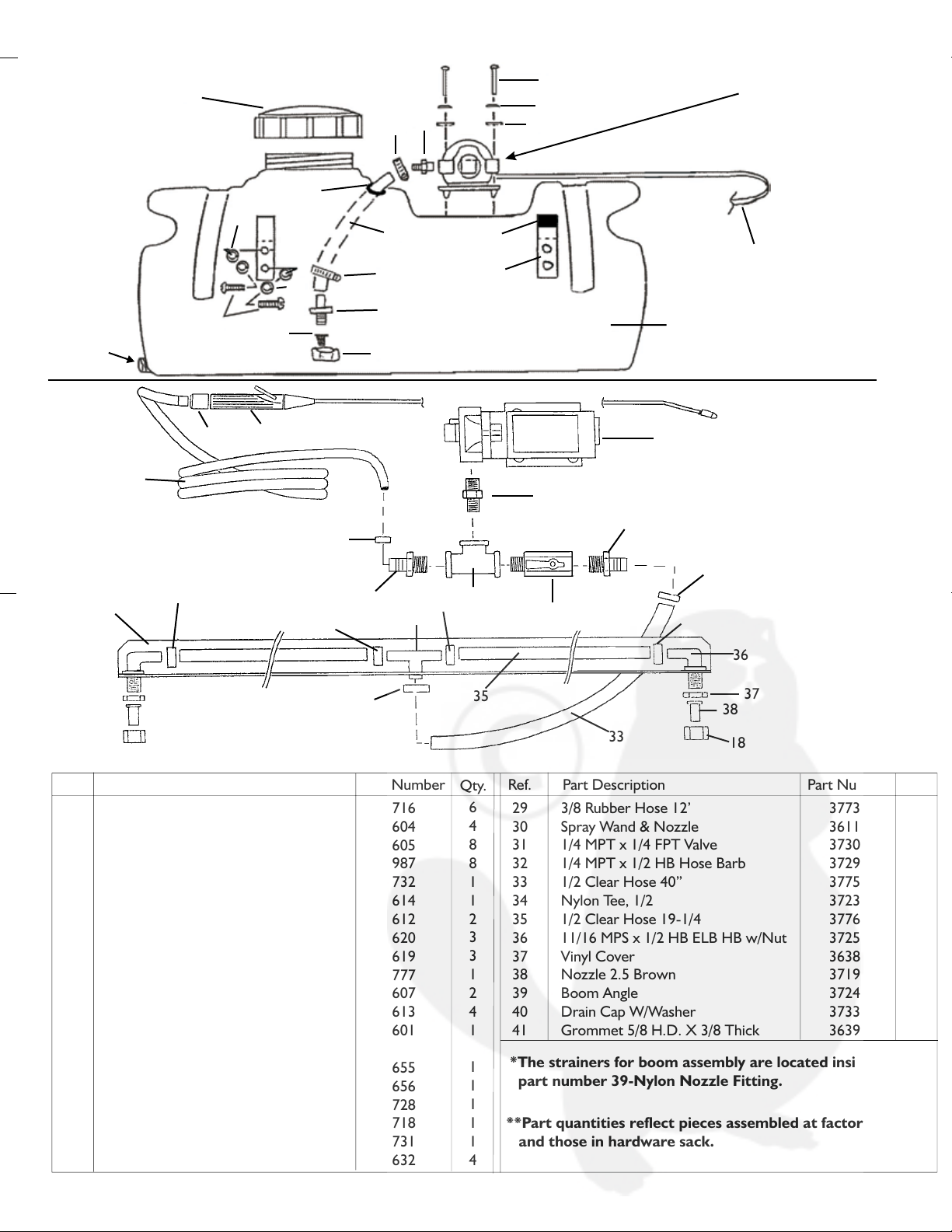
PLUMBING ASSEMBLY
STEP 2 Attach Boom Mount to Cart Body using 5/16” x 3/4” Hex Head Bolts(2), 5/16” Flat Washers(4), 5/16” Lock Washers(5)
and 5/16” Hex Head Nuts (6),(Fig.5). Attach Boom Arm Assembly to Boom Mount using 5/16” x 3/4” Hex Head Bolts(2),
5/16” Flat Washers(4), 5/16” Lock Washers(5) and 5/16” Hex Head Nuts(6), (Fig. 6). Tighten all four Bolts with the 1/2”
wrenches.
Parts List for Pump Assembly
SEE BELOW FOR PLUMBING
ASSEMBLY
12
13
15
16
17
18
19
21
28
28
20
13
14
21
22
23
24
28
27
28
26
25
29
30
31
11
32
11
11 11
33
34
35
36
37
18
38
11
5/16” Hex Head Nut
5/16” Lock Washer
Fig. 6
14
Hose from Ball
Valve off of Pump
11
40
39
**Part quantities reflect pieces assembled at factory
and those in hardware sack.
Boom Arm
Assembly
Drain Cap
*The strainers for boom assembly are located inside
part number 39-Nylon Nozzle Fitting.
Introduction
Your sprayer has been manufactured to provide the maximum
in dependable efficient use. Proper operation and maintenance
will ensure long satisfactory service. Study this manual carefully
to become familiar with the operation and maintenance
instructions.
Keep your manual in a safe, convenient place for future
reference. Always mention the model and part number in any
correspondence. To insure correct parts service be sure to
use part number and description when ordering.
Operation
Operating power is obtained from a 12 volt direct source or
cigarette lighter plug. Be sure to connect the red to the
positive (+) source and attach the black to the negative ( - )
source.
Before spraying chemicals, fill the tank full
of plain water to allow familiarization with the sprayer and to
prevent waste of expensive chemicals.
IMPORTANT:
Sprayer Maintenance
.
A sprayer is a carefully designed and built machine that should
provide many years of reliable service if properly cared for.
The main rule in caring for any sprayer is:
Neglect costs dollars in repairs, wasted spray material and
premature replacement of the sprayer.
KEEP IT CLEAN
Cleaning & Storage
Most spray materials are highly corrosive. The most important
aspect of long dependable service from the sprayer is a thorough
cleaning immediately following each use. In addition, the residue
of one type of chemical could cause an undesirable effect when a
different chemical is used for a different purpose.
The most effective cleaning method is to pump several rinses of
clean water through the tank, pump, hoses, boom, spray gun, etc.
A neutralizing agent such as a solution of Nutra-Sol, a detergent or
household ammonia as recommended by the chemical manufacturer
can assist in removal of a persistent chemical. When the system is
thoroughly cleaned drain the tank, suction line, pump, hoses, etc.
The following steps should be followed for the maintenance and
storage of your sprayer.
1. Wash and flush out sprayer after completion of each phase
of your program. Flush out sprayer when changing chemicals if
there is a possibility of the chemicals being incompatible. Use of a
detergent is advisable if the chemical manufacturer does not make
specific cleaning recommendations. Flush system completely,
including nozzles. Never use metal objects to open clogged
nozzles.
2. Clean sprayer thoroughly before storing at the end of the
spraying season. Permanent type anti-freeze added to the final
rinse will leave a rust inhibiting film in parts of the sprayer.
37
41
Rear View
5/16” Hex Head Bolts
5/16” Flat Washer
Fig. 5
Boom Mount
Assembly Instructions Continued
Ref. Part Description Part Number
6
4
8
8
1
1
2
3
3
1
2
4
1
1
1
1
1
1
4
11
12
13
14
15
16
17
18
19
20
21
22
23
24
25
26
27
28
Part Description
Ref. Part Number Qty.
Hose Clamp .702 - .801 Plastic
10-24 x 1-1/4 Round Head Screw
#10 Flat Washer (10FWZP)
3/16” Lock Washer
Wire Harness
15 Gallon Sprayer Tank
Wand Holder
Nozzle Cap
Suction Strainer*
3/8 Rubber Hose 24”
Hose Barb 3/8 MPT x 3/8 HB
10-24 x 1/2 Bolt
Tank Lid
Pump Electric: Check Model Number
Models TCT15-12V (1.0 W/O Switch)
Models TCT15RT-12V (1.0 W/ Switch)
3/8” MPT x 1/4” MPT Nipple
Nylon Tee, 1/4”
1/4 MPT x 3/8 HB
1/2” Stainless Steel Clamp
3716
3604
3605
2987
3732
3614
3612
3620
3619
3777
3607
3613
3601
3655
3656
3728
3718
3731
3632
Qty.
29
30
31
32
33
34
35
36
37
38
39
40
41
3/8 Rubber Hose 12’
Spray Wand & Nozzle
1/4 MPT x 1/4 FPT Valve
1/4 MPT x 1/2 HB Hose Barb
1/2 Clear Hose 40”
Nylon Tee, 1/2
1/2 Clear Hose 19-1/4
11/16 MPS x 1/2 HB ELB HB w/Nut
Vinyl Cover
Nozzle 2.5 Brown
Boom Angle
Drain Cap W/Washer
Grommet 5/8 H.D. X 3/8 Thick
3773
3611
3730
3729
3775
3723
3776
3725
3638
3719
3724B
3733
3639
1
1
1
1
1
1
2
2
2
2
1
1
1
PLUMBING ASSEMBLY
STEP 2 Attach Boom Mount to Cart Body using 5/16” x 3/4” Hex Head Bolts(2), 5/16” Flat Washers(4), 5/16” Lock Washers(5)
and 5/16” Hex Head Nuts (6),(Fig.5). Attach Boom Arm Assembly to Boom Mount using 5/16” x 3/4” Hex Head Bolts(2),
5/16” Flat Washers(4), 5/16” Lock Washers(5) and 5/16” Hex Head Nuts(6), (Fig. 6). Tighten all four Bolts with the 1/2”
wrenches.
Parts List for Pump Assembly
SEE BELOW FOR PLUMBING
ASSEMBLY
12
13
15
16
17
18
19
21
28
28
20
13
14
21
22
23
24
28
27
28
26
25
29
30
31
11
32
11
11 11
33
34
35
36
37
18
38
11
5/16” Hex Head Nut
5/16” Lock Washer
Fig. 6
14
Hose from Ball
Valve off of Pump
11
40
39
**Part quantities reflect pieces assembled at factory
and those in hardware sack.
Boom Arm
Assembly
Drain Cap
*The strainers for boom assembly are located inside
part number 39-Nylon Nozzle Fitting.
Introduction
Your sprayer has been manufactured to provide the maximum
in dependable efficient use. Proper operation and maintenance
will ensure long satisfactory service. Study this manual carefully
to become familiar with the operation and maintenance
instructions.
Keep your manual in a safe, convenient place for future
reference. Always mention the model and part number in any
correspondence. To insure correct parts service be sure to
use part number and description when ordering.
Operation
Operating power is obtained from a 12 volt direct source or
cigarette lighter plug. Be sure to connect the red to the
positive (+) source and attach the black to the negative ( - )
source.
Before spraying chemicals, fill the tank full
of plain water to allow familiarization with the sprayer and to
prevent waste of expensive chemicals.
IMPORTANT:
Sprayer Maintenance
.
A sprayer is a carefully designed and built machine that should
provide many years of reliable service if properly cared for.
The main rule in caring for any sprayer is:
Neglect costs dollars in repairs, wasted spray material and
premature replacement of the sprayer.
KEEP IT CLEAN
Cleaning & Storage
Most spray materials are highly corrosive. The most important
aspect of long dependable service from the sprayer is a thorough
cleaning immediately following each use. In addition, the residue
of one type of chemical could cause an undesirable effect when a
different chemical is used for a different purpose.
The most effective cleaning method is to pump several rinses of
clean water through the tank, pump, hoses, boom, spray gun, etc.
A neutralizing agent such as a solution of Nutra-Sol, a detergent or
household ammonia as recommended by the chemical manufacturer
can assist in removal of a persistent chemical. When the system is
thoroughly cleaned drain the tank, suction line, pump, hoses, etc.
The following steps should be followed for the maintenance and
storage of your sprayer.
1. Wash and flush out sprayer after completion of each phase
of your program. Flush out sprayer when changing chemicals if
there is a possibility of the chemicals being incompatible. Use of a
detergent is advisable if the chemical manufacturer does not make
specific cleaning recommendations. Flush system completely,
including nozzles. Never use metal objects to open clogged
nozzles.
2. Clean sprayer thoroughly before storing at the end of the
spraying season. Permanent type anti-freeze added to the final
rinse will leave a rust inhibiting film in parts of the sprayer.
37
41
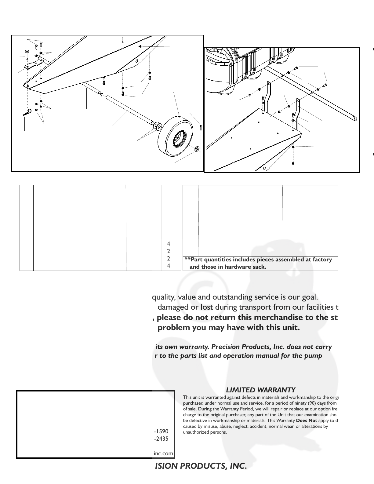
Fig. 3
3/4” Flat Washer
Cotter Pin
Axle Slot
Fig. 1
Ref.
No.
Part
No.
1 1840 1/2”x 1-3/4” Clevis Pin
2 1248 5/16” x 3/4” Hex Head Bolt
3 1042 #14 Hitch Pin Clip
4 1044 5/16” Flat Washer
5 1276 5/16” Lock Washer
6 1275 5/16” Hex Head Nut
7 3739 3/4” In Diam. x 2” Flat Washer
8 1264 3/4” Flat Washer
9 1262 1/8” x 1-1/4” Cotter Pin
1
6
1
6
6
6
4
2
2
Part Description
Hardware
Sack Qty.
Trailer Sprayer
ASSEMBLY INSTRUCTIONS & PARTS LIST 03/05
PRECISION PRODUCTS, INC.
3736-6
Assembly Hardware
Assembly Instructions
Cart Body Assembly Parts
LIMITED WARRANTY
This unit is warranted against defects in materials and workmanship to the original
purchaser, under normal use and service, for a period of ninety (90) days from date
of sale. During the Warranty Period, we will repair or replace at our option free of
charge to the original purchaser, any part of the Unit that our examination shows to
be defective in workmanship or materials. This Warranty apply to damage
caused by misuse, abuse, neglect, accident, normal wear, or alterations by
unauthorized persons.
Does Not
The electric pump on this model has its own warranty. Precision Products, Inc. does not carry
a warranty on the pump. Please refer to the parts list and operation manual for the pump
included with this model.
PRECISION PRODUCTS, INC.
Fig.3
Tools needed for assembly:
Two 1/2” Wrenches
1 Pair Needle Nose Pliers
123
5
8
9
7
6
4
Fig. 2
3/4” Diameter x 2”
Flat Washers
Axle
1/2”x 1-3/4” Clevis Pin
5/16” x 3/4” Hex Head Bolt
#14 Hitch Pin Clip
5/16” Flat Washer
5/16” Lock Washer
5/16” Hex Head Nut
3/4” Diameter x 2” Flat Washer
3/4” Flat Washer
1/8” x 1-1/4” Cotter Pin
5/16” x 1/2” Hex Head Bolt
1
2
4
42
6
3
43
44
7
10
5
8
9
2
4
45
47
5
6
5
6
62
4
5/16” Lock
Washers
Fig. 4
5/16” x 1” Hex
Head Bolts
5/16” Flat
Washers
Clevis
5/16” Hex
Head Nuts
46
STEP 1 Insert Axle through Axle Slot on Cart Body. Once the Axle is through the hole, slide on one 3/4” x 2” Flat Washer(7) then the
Axle Tube Spacer(44), then slide the Axle through to the end of the Axle T
ube Spacer. Add another 3/4” x 2” Flat Washer (inside
of the Sprayer Cart body) and push the Axle through the other hole on the Cart Body. Once the Axle is through the second hole,
slide on a 3/4” ID x 2” Flat Washer(7), (Fig.2). Now slide on a wheel followed by a 3/4” Flat Washer(8) and then secure with
a Cotter Pin(9). Repeat this for both Wheels. Use Needle Nose Pliers to bend back ends of the Cotter Pin,(Fig.3). Repeat for
other side. Using 5/16” x 3/4” Hex Head Bolts(2), 5/16” Flat Washers(4), 5/16” Lock Washers(5), and 5/16” Hex Head Nuts(6)
attach Clevis, (42),(on topside of Cart Body) to the Cart Body (Fig. 4). Tighten Bolts with 1/2” wrenches. Insert Clevis Pin(1)
through Clevis and secure with #14 Hitch Pin Clip(3) underneath Cart Body.
1
2
3
4
5
6
7
8
9
10
Ref. Part Description Part Number
Qty.
1840
1248
1042
1044
1276
1275
3739
1264
1262
1249
1
6
1
6
10
6
4
2
2
4
42
43
44
45
46
47
Ref. Part Description Part Number
Qty.
Clevis
Axle
Axle Tube Spacer
10” Pneumatic Wheel for TCT
TCT Cart Body
Boom Mount
1243P
3769
3767
3768
3740R
3766R
1
1
1
2
1
1
**Part quantities includes pieces assembled at factory
and those in hardware sack.
TCT15
TCT15RT
Cart Body
3/4” Diameter x 2”
Flat Washers
Axle Spacer
5
When ordering parts, always give model number,
part description, & part number.
Precision Products, Inc.
Parts Division (217)735-1590
316 Limit Street (217)735-2435
Lincoln, IL 62656
or visit us on the world wide web :www.precisionprodinc.com
Send To:
Phone
Fax
Customer Service
CUSTOMER SUPPORT
At Precision Products, Inc. delivering quality, value and outstanding service is our goal.
However, sometimes parts do become damaged or lost during transport from our facilities to
the store. If you have any problems, please do not return this merchandise to the store.
Call us and we will take care of any problem you may have with this unit.
This manual suits for next models
1


