Precision 815 Manual

Installation/Service Manual
Microprocessor Controlled
Low Temperature Incubator
Model 815
Precision
170 Marcel Drive
Winchester, VA
USA
Phone: 540-869-8623
Toll Free: 800-621-8820
FAX: 540-869-8626
Manual P/N 36100114 (34001729)
Rev D Dated 15 December, 2004

NOTICE
THE MATERIAL IN THIS MANUAL IS FOR INFORMATION PURPOSES ONLY. THE
CONTENTS AND THE PRODUCT IT DESCRIBES ARE SUBJECT TO CHANGE WITHOUT
NOTICE. PRECISION MAKES NO REPRESENTATIONS OR WARRANTIES WITH RESPECT
TO THIS MANUAL. IN NO EVENT SHALL PRECISION BE LIABLE FOR ANY DAMAGES,
DIRECT OR INCIDENTAL, ARISING OUT OF OR RELATED TO THE USE OF THIS
MANUAL.
For repair information or replacement parts assistance from the manufacturer,
call Customer Service using our toll free telephone number.
800-621-8820
(FAX) 540-869-0130

Initial Release
A
INDEX DATE AMENDED PAGES NOTES
REVISION STATUS
6/99
B 8/99 19 Update parts list for new kit #'s
C 9/01 Removed dual fans, updated parts list18-20
D 12/04 Update for base model FFU2064DW118-20

Contents
Introduction .......................................................................................................................... 1
Unpacking and Damage ....................................................................................................... 1
General Information .............................................................................................................2
Performance Data ................................................................................................................2
Explanation of Controls ........................................................................................................ 3
Instrumentation Port ............................................................................................................. 5
Installation ............................................................................................................................ 6
Operation ............................................................................................................................. 7
Servicing .............................................................................................................................. 8
Troubleshooting ................................................................................................................... 8
Maintenance ....................................................................................................................... 12
Installation and Operation
of the RS232 Option ........................................................................................................... 13
Wiring Diagrams .................................................................................................................17
Parts Replacement List ...................................................................................................... 19
Warranty ............................................................................................................................. 20

1
INTRODUCTION
Your satisfaction and safety are important to
PRECISION and a complete understanding of this
unit is necessary to attain these objectives.
As the user of this apparatus, you have the
responsibility to understand the proper function
and operational characteristics of your incubator.
This instruction manual should be thoroughly read
and all operators given adequate training before
attempting to place this unit in service. Awareness
of the stated cautions and warnings, and
compliance with recommended operating
parameters, together with maintenance
requirements, are important for safe and
satisfactory operation. The unit should be used
for its intended application; alterations or
modifications will VOID THE WARRANTY.
WARNING
AS A ROUTINE LABORATORY PRECAUTION,
ALWAYS WEAR SAFETY GLASSES WHEN
WORKING WITH THIS APPARATUS.
This product is not intended, nor can it be used,
as a sterile or patient connected device. In
addition, this apparatus is not designed for use in
Class I, II or III locations as defined by the National
Electrical Code.
UNPACKING AND DAMAGE
Save all packing material until unit is put into
service. This merchandise was carefully packed
and thoroughly inspected before leaving our
factory.
Responsibility for safe delivery was assumed by
the carrier upon acceptance of the shipment;
therefore, claims for loss or damage sustained in
transit must be made upon the carrier by the
recipient as follows:
1. Visible Loss or Damage: Note any external
evidence of loss or damage on the freight bill,
or express receipt, and have it signed by the
carrier's agent. Failure to adequately describe
such external evidence of loss or damage may
result in the carrier's refusing to honor your
damage claim. The form required to file such
claim will be supplied by the carrier.
2. Concealed Loss or Damage: Concealed loss
or damage means loss or damage which does
not become apparent until the merchandise
has been unpacked and inspected. Should
either occur, make a written request for
inspection by carrier's agent within fifteen (15)
days of the delivery date; then file a claim with
the carrier since the damage is the carrier's
responsibility.
If you follow the above instructions carefully, we
will guarantee our full support of your claim to be
compensated for loss or concealed damage.
DO NOT -- FOR ANY REASON -- RETURN THIS
UNIT WITHOUT FIRST OBTAINING
AUTHORIZATION. In any correspondence to
PRECISION, please supply the nameplate data,
including catalog number and serial number.

2
GENERAL INFORMATION
The incubator is commonly referred to as the
standard Model 815. These instructions
encompass the models listed below with their
specific electrical characteristics.
PERFORMANCE DATA
Heat-Up Time: From -10°C to 50°C; 120 minutes
(Compressor "ON");
Cool-Down Time: From 50° to -10°C; 100 minutes.
NOTE
THE ABOVE PERFORMANCE FIGURES ARE BASED
UPON THE FOLLOWING OPERATING CONDITIONS:
LINE VOLTAGE ............... 110.5 TO 112.5
AMBIENT TEMPERATURE ... 22.5° TO 24°C
Theory of Operation
The refrigeration system, defrost heater, and air
circulating fan are used in conjunction with a
microprocessor controlled proportioning circuit to
achieve sensitive temperature control. A RTD
(Resistance Temperature Detector) located in the
airstream senses any temperature deviation from
the control point, and heat is provided
proportionally to maintain the desired temperature.
Regardless of what temperature is being
maintained, the compressor operates
continuously. This constant operation alleviates
component failures associated with cycle type
operation.
The circulating fan provides even air distribution
throughout the chamber and assures temperature
uniformity.
CATALOG NO. 51220105 CAN BE CONVERTED FOR
OPERATION ON 200V OR 240V BY CHANGING
INPUT CONNECTIONS TO THE
AUTOTRANSFORMERS (SEE WIRING DIAGRAM ON
PAGE 17).
The 815 Low Temperature Incubator has been
designed to provide the ultimate in temperature
control. The user is assured of dependable and
precise performance through the use of
microprocessor technology in the temperature
control circuitry. The Model 815 Incubator is
operable in the range of -10° to 50°C. These
temperature ranges will meet a wide variety of
applications, such as BOD determination, general
incubation and as well as the preservation of critical
materials.
NOTE
518LEDOM
golataCstloVzHspmA
60112215
50112215
511
032
06
06
0.7
5.3
MODEL 815
Temperature
Set Point
°C
Uniformity
±°C
Temperature
Sensitivity
-10.0 ±0.9
±0.1C
20.0 ±0.5
37.0 ±0.5
50.0 ±0.6

3
EXPLANATION OF CONTROLS
-Front Panel-
1) HEATER ON LAMP - The "Heater On" lamp is
illuminated when power is applied to the heater.
2) LED DISPLAY - Four digits are used to display
the actual, set, calibrate, high limit and low limit
values.
3) INDICATOR LAMPS - There are five (5) green
indicator lamps that are used to inform the user
which parameter the display is indicating. The sixth
indicator is for a high or low temperature alarm
condition. An internal audible alarm will also
operate when this alarm indicator illuminates.
4) ON/OFF SWITCH - The On/Off switch provides
the main power to the incubator.
5) MUTE KEY - This key is used to silence the
internal audible alarm and to also de-activate the
external alarm device if one is being used.
6) HIGH/LOW LIMIT KEY - This key is used to
view the high or low temperature alarm setpoint
The first depression of the key selects the high
limit. The second depression selects the low limit.
The respective green indicator lamp will light.
7) SET TEMP/CAL KEY - This key is used to view
the operating setpoint temperature or calibrate the
unit to a certified/traceable thermometer. The first
depression of the key selects the operating setpoint
and the second depression selects the calibration
mode. The respective green indicator lamp will
light.
8) ENTER KEY - This key is used after any setpoint
selection is made to enter the value into memory.
9) UP/DOWN ARROW KEYS - These keys are
used to increase or decrease the desired setpoint
value.
123
4
5
6
7
8
9

4
-Explanation of Auxiliary Panel-
On the left side of the incubator control panel there
is an auxiliary panel which has the items shown in
the figure below. They are described as follows:
1) FUSE - This fuse is in line with the main power
cord that comes into the incubator. The rating of
this fuse is printed above the fuse holder. The
physical size of this fuse is 5 MM x 20 MM.
2) ALARM RELAY - This Alarm Relay output is
provided to the user for the purpose of remotely
monitoring the incubator in case of a high or low
temperature alarm condition. This alarm relay will
operate just as the audible alarm would. The
contact itself is an isolated form C (normally open/
normally closed) dry contact. This contact is to be
used for low voltage class 2 connections only. The
contact rating is 24 volts, 1.25 amps resistive.
Typical usages of the output are shown below.
In this configuration, the light will illuminate
whenever the unit goes into an alarm
condition...High or Low.
Temperature
(Degree C)
Recorder
Output
(Millivolts)
-10 100
0200
10 300
20 400
30 500
40 600
50 700
In this configuration, the light will go off in a high or
low temperature alarm condition.
NOTE
WIRING MUST CONFORM TO ALL LOCAL
ELECTRICAL CODES.
3) RS-232 OUTPUT (Optional Kit P/N 51200906) -
This output is used for two way communications
between the incubator and a personal computer.
With the use of communications/modem software
program, the user can record the temperature of
the incubator at their selected time periods and
store it in a file for use with a spreadsheet program.
The user can also change the setpoint temperature
from their personal computer and periodically
monitor the actual temperature, setpoint
temperature, and alarm status.
4) RECORDER OUTPUT - This is a DC millivolt
output which represents the temperature of the
incubator. The recommended main use of this is
with a chart recorder having an input impedance
of at least 1 megohm. The scaled temperature
output change is 10 millivolt/degree C. When the
incubator is operating at a negative temperature,
the chart recorder output is still positive. Use the
chart below to relate temperature to output voltage.
VOLTAGE SOURCE
VOLTAGE SOURCE

5
Located on the chart recorder printed circuit board
is an offset potentiometer R3. If for some reason
the recorder output voltage does not match the
temperature as shown in the chart, this
potentiometer can be used to tune it in.
When connecting a chart recorder to the recorder
output connector, it is recommended to use a
shielded cable with the shield grounded at the chart
recorder and to keep the cable short as possible.
INSTRUMENTATION PORT
Located on the rear side of the incubator is an
instrumentation port for the user to insert sensor
wires, external meter leads, etc. into the chamber.
The rubber plug provided must always be used in
this port to insure the uniformity specifications. An
extra plug is supplied for the user's convenience.
Be sure to seal any gaps around the wire(s) going
through the plug.

6
INSTALLATION
Location
To assure proper ventilation, allow a minimum of
4" of clearance between the rear, top, and sides
of the incubator and adjacent walls. If two or more
incubators are positioned side by side, allow a
minimum of 8" between cabinets. Adjust the front
leveling feet of the incubator so that the front is
higher than the rear. This will assist in door closing.
Choose a site free from rapidly changing ambient
temperature conditions.
CAUTION
THE INCUBATOR SHOULD NOT BE OPERATED IN
AN ENVIRONMENT WHERE THE AMBIENT
TEMPERATURE EXCEEDS 90°F, AS THE
COMPRESSOR THERMO-OVERLOAD WILL BE
TRIPPED AND WILL RESULT IN A WIDE BAND
CONTROL CYCLE OF APPROXIMATELY ±4°C.
SUCH CYCLING SHOULD NOT BE
MISINTERPRETED AS A MALFUNCTION OF THE
ELECTRONIC CONTROLS.
Radiators, air-conditioning outlets, other ventilating
system outlets, and drafts can affect the operation
of the incubator by a sudden inrush of air that is at
a temperature different than operating conditions.
WARNING
FOR PERSONAL SAFETY, THIS APPARATUS MUST
BE PROPERLY GROUNDED.
The power cord of this instrument is equipped with
a three-prong (grounding) plug which mates with
a standard three-prong (grounding) wall receptacle
to minimize the possibility of electric shock hazard
from this apparatus. The customer should have
the wall receptacle and circuit checked by a
qualified electrician to make sure the receptacle is
properly grounded.
Where a two-prong wall receptacle is encountered,
it is the personal responsibility and obligation of
the user to have it replaced with a properly
grounded three-prong wall receptacle.
WARNING
DO NOT -- UNDER ANY CIRCUMSTANCES, CUT OR
REMOVE THE THIRD (GROUND) PRONG FROM
THE POWER CORD. DO NOT USE A TWO-PRONG
ADAPTER PLUG.
Determine the total amount of current presently
being used by other apparatus connected to the
circuit that will be used for this unit.
It is critical that the added current demand and
other equipment on the circuit not exceed the rating
of the fuse or circuit breaker in use.
CAUTION
BE SURE THAT THE POWER SUPPLY IS OF THE
SAME VOLTAGE AS SPECIFIED ON THE
NAMEPLATE.
When loading the incubator, a space of 1/2" must
be allowed between adjacent items. This will allow
maximum air circulation, which is necessary for
proper temperature uniformity. The uniformity will
be adversely affected if air circulation is obstructed.
Liquid containers should never be placed in the
incubator without covers. The evaporation of
moisture within the chamber will only add frost and
hasten the need for defrosting. This chamber is
not self-defrosting.
Excessive frost buildup on the evaporator coil
located on the lower rear wall will also affect
temperature uniformity.
WARNING
SAFETY PRECAUTIONS
1. DO NOT PLACE ANY EXPLOSIVE,
COMBUSTIBLE, OR FLAMMABLE MATERIALS IN
THE CHAMBER.
2. DO NOT PLACE SEALED CONTAINERS IN THE
CHAMBER. SEALED CONTAINERS, FILLED WITH
MATERIALS DO NOT PROVIDE ROOM FOR
EXPANSION AND CAN DEVELOP DANGEROUS
VAPOR PRESSURE AS THE TEMPERATURE
INCREASES.
3. AVOID SPILLAGE OF LIQUIDS WITHIN THE
CHAMBER.
4. DO NOT EVAPORATE NOXIOUS FUMES.
CAUTION
DO NOT STORE CONTAINERS FILLED WITH ACIDIC
OR CAUSTIC SOLUTIONS, AS VAPORS FROM
THESE MATERIALS WILL ATTACK THE
EVAPORATOR AND VOID THE WARRANTY.

7
OPERATION
Power up by depressing the ON/OFF switch.
Immediately after turning on power, all the
segments of the display and all of the indicators
will be on. After one second the display will show
the actual temperature and the actual temperature
indicator light will be lit. If the setpoint temperature
is greater than the actual temperature, then the
heater on lamp will be on or start to flash. If it
flashes, then the actual temperature is near
setpoint temperature.
To display any TEMPERATURE VALUE - With the
use of either the SET TEMP/CAL key or the HIGH/
LOW LIMIT key, any temperature value can be
displayed. To view the set temperature, press the
SET TEMP/CAL key once. The green indicator for
the set temperature will light. If no other keys are
pressed, within 5 seconds, the display will
automatically return to the actual temperature. To
view the calibrate temperature, press the SET
TEMP/CAL twice while the display is showing the
actual temperature. The same sequence of key
operation is true for the use of the HIGH/LOW
LIMIT key.
To change the SETPOINT TEMPERATURE -
Press the SET TEMP/CAL key once. Then press
the UP or DOWN arrow key until the desired
temperature is displayed. When continuously
pressing either the UP or DOWN keys, the display
will begin to change rapidly. With a little practice,
one will become accustomed to this. After the
desired set temperature is achieved, then press
the ENTER key. The display will then return to
showing the actual temperature. If the ENTER key
is not pressed, the expected new set temperature
will not be accepted and the incubator will control
at the previous set temperature.
To CALIBRATE the INCUBATOR - The incubator
is calibrated at the factory for use over a wide range
of temperatures. Due to the slight non-linearities
in the control system, it may be necessary to make
the display match a calibrated thermometer's
reading, even though the difference might be only
a few tenth's of a degree.
The CALIBRATE key should be used ONLY to
match a stable incubator's actual temperature to
the calibrated thermometer.
Place a calibrated thermometer or the probe of one
at the center of the third shelf of the incubator.
Select the SETPOINT you wish to run the unit at.
Allow the unit to run for at least an hour after it
reaches the setpoint, before you perform the
calibration.
NOTE
IF POSSIBLE PLACE THE THERMOMETER INTO A
LIQUID FOR STABILITY.
To perform calibration, press the SET TEMP/CAL
twice. The green calibration indicator should be
lit. Then press either the UP or DOWN arrow keys
to make the display match the noted thermometer
reading. After the satisfied display is achieved,
press the ENTER key. The display will then return
to showing the newly calibrated actual
temperature.
To change the HIGH TEMPERATURE ALARM
SETPOINT - After selecting a setpoint
temperature, the HIGH TEMPERATURE ALARM
SETPOINT automatically defaults to 1° higher than
the setpoint that was entered. This 1° default
difference can be overridden if the user wishes to.
The following paragraph describes this.
Press the HIGH/LOW LIMIT key once. The green
"High Temperature alarm/Set Point" indicator
should be lit. Use the UP or DOWN arrow keys to
select your limit value. Then press the ENTER key.
If the HIGH LIMIT value you have selected is below
the operating SETPOINT TEMPERATURE, the
incubators' alarm will activate
To change the LOW TEMPERATURE ALARM/
SETPOINT - After selecting a setpoint
temperature, the LOW TEMPERATURE
SETPOINT automatically defaults to 1° lower than
the setpoint that was entered. This 1° default
difference can be overridden if the user wishes to.
The next paragraph describes this.

8
TROUBLESHOOTING
Problems encountered with any constant
temperature chamber will most frequently be
related to temperature control. Before proceeding
with detailed troubleshooting, be certain that the
Low Limit and High Limit controls are adjusted
properly. If the limit controls are set too close or
beyond the operating temperature, the incubator
may be consistently going into alarm. This will
result in erratic temperature control. First, the
symptoms and possible causes will be listed for
quick reference. Later, the remedies will be
suggested.
WARNING
HAZARDOUS HIGH VOLTAGE CONDITIONS EXIST
INSIDE THE CONTROL PANEL. UNPLUG LINE
CORD AND TURN "OFF" LINE SWITCH BEFORE
REMOVING THE COVER. ONLY QUALIFIED
ELECTRICAL INSTRUMENT PERSONNEL ARE
AUTHORIZED TO PERFORM TROUBLESHOOTING
AND/OR SERVICING.
SYMPTOMS AND POSSIBLE CAUSES:
Freeze-up or gradual drop in chamber
temperature:
No air circulation in chamber; inoperative fan (see
Remedy 1)
Heater (see Remedy 2)
Power Supply PCB Assembly (see Remedy 3)
RTD Temperature Probe (see Remedy 3, Step D
and/or Remedy 4).
Temperature variations at set point (poor
control):
Excessive ambient temperature variations (see
Remedy 10)
Compressor Relay failure (see Remedy 12)
No air circulation in chamber; inoperative fan (see
Remedy 1)
RTD Temperature Probe Location (see Remedy
5)
Ice buildup on evaporator coils (see paragraph on
"Defrosting")
RTD Temperature probe (see Remedy 3, Step D
and/or Remedy 4).
Power Supply PCB Assembly (see Remedy 3)
Press the HIGH/LOW LIMIT key twice. The green
"Low Temperature Alarm/Setpoint" indicator
should be lit. Use the UP or DOWN arrow keys to
select your limit value. Then press the ENTER key.
If the LOW LIMIT value you have selected is above
the operating setpoint temperature, the incubators'
alarm will activate.
NOTE
SOFTWARE VERSION 2.00 HAS A 30-MINUTE
DELAY FOR THE LOW AND HIGH ALARM TO AVOID
NUISANCE ALARMS CAUSED BY DOOR
OPENINGS.
SERVICING
WARNING
SERVICE SHOULD BE PERFORMED ONLY BY
QUALIFIED SERVICE PERSONNEL. EXERCISE
CARE AS LINE VOLTAGE IS PRESENT IN THE
CONTROL COMPARTMENT.
If it is ascertained, after review of the
Troubleshooting Section, that refrigeration service
is needed, contact the White-Westinghouse
Service Organization.
In any communication with White-Westinghouse
or Precision, include the model and serial numbers
from both nameplates located near the bottom of
the door opening. Specific reference must be made
to White-Westinghouse Policy Procedure Letter
82-2605, which covers the service requirements
for this particular model.
For assistance in locating the nearest White-
Westinghouse authorized service or parts supplier,
contact:
White-Westinghouse
P.O. Box 7181
Dublin, OH 43017
1(800) 245-0600

9
Does not reach a high set point temperature:
No air circulation in chamber; inoperative fan (see
Remedy 1)
Low line voltage, less than 110V (see Remedy 9)
RTD Temperature Probe (see Remedy 3, Step D
and/or Remedy 4).
Power Supply PCB Assembly (see Remedy 3)
Overcharged compressor (see Remedy 11)
Differences between Temperature Set and
Digital Temperature Readout: (see
performance figures, page 3)
RTD Temperature Probe (see Remedy 3, Step D
and/or Remedy 4).
Malfunctioning Power Supply PCB assembly (see
Remedy 3)
Takes an extremely long time to reach high
temperature set point:
No air circulation in chamber; inoperative fan (see
Remedy 1)
Low line voltage, less than 110V (see Remedy 9)
Power Supply PCB assembly (see Remedy 3)
Overcharged Compressor (see Remedy 11)
Display indicates or
Malfunctioning RTD Temperature Probe (Remedy
4)
POSSIBLE REMEDIES:
1. Inoperative Fan:
Open the door. Place your hand near the grill
at the top rear of the chamber and check for
air circulation. If there is no air circulation, the
fan motor is malfunctioning. Contact White
Westinghouse for replacement part. See page
8.
2. Burned-out heater:
To check this, the control panel cover must
be removed.
WARNING
HAZARDOUS HIGH VOLTAGE CONDITIONS EXIST
INSIDE CONTROL PANEL. TURN "OFF" LINE
SWITCH ON FRONT PANEL AND UNPLUG LINE
CORD.
Remove all screws that fasten the cover.
Locate nylon connector J1 on the Limit/Alarm
PCB Assembly. Depress both ears on the
plug housing and gently pull out the connector.
With an Ohmmeter, measure the resistance
between TB1-4 (Orange wire) and TB1-6
(Red wire).
The proper heater resistance is 24 ohms. If
heater resistance is correct, then measure
between one heater lead (RED or ORANGE)
and incubator ground, it must be infinity
(Open). If the heater resistance check
indicates an open circuit, it may or may not
be open. In series with the heater is a thermal
overload switch. It might be that this thermal
overload is open and not the heater. To check
the heater and thermal switch directly, the
shelfs of the incubator and the back wall cover
must be removed. Unplug heater and
measure its' resistance. If the resistance is
correct, check resistance between heater
terminal and the heater sheath. It must be an
open circuit. If the heater is good, then check
the thermal overload switch. At room
temperature it should be closed (0 ohms). This
switch should only open at 80°C and then
close at 65°C. If the heater and thermal switch
are good, then the problem is directed towards
the heater wires in the harness. If heater is
defective, contact White-Westinghouse for
replacement heater. See page 7.
3. Malfunctioning Power Supply PCB assembly:
The Power Supply PCB Assembly has the
triac (solid state AC voltage switch) on it which
supplies the power to heater. This triac is "told"
to operate, when need be, by the
microprocessor.

10
There is another device known as an
Optoisolator which serves as the high/low
voltage isolator between the triac and the
microprocessor.
When the incubator starts experiencing
temperature problems and/or variations, due
to known controller malfunctions, these two
components become prime suspects. The
reason being they are under higher operating
stress than other components.
If the incubator starts experiencing
temperature problems such as no heat,
constant heat, or "creeping" upward heat, then
follow the troubleshooting instructions below.
These instructions require the use of a
voltmeter being able to measure DC and AC
voltages and preferably a digital voltmeter.
WARNING
THE FOLLOWING TROUBLESHOOTING
INSTRUCTIONS REQUIRE THAT POWER BE ON. ONLY
QUALIFIED SERVICE PERSONNEL SHOULD PERFORM
THESE PROCEDURES.
A) Remove the control cover and familiarize
yourself with the power supply assembly
#34394901. Locate the Triac (Q2), the Opto-
isolator (U1), resistor (R4). Also locate the test
point #2 (TP2). The first measurements will
be DC voltage measurement, so a DC scale
of at least 10 volts should be selected.
Connect the negative lead to TP2. This is DC
ground. Also locate the terminal block (TB1).
B) This first section will be to verify the heater
command is correct from the microprocessor,
through the optoisolator, and through the Triac
when the incubator is NOT requesting heat.
The steps in this section must be followed in
progression.
-Select a setpoint temperature at least 10°
below what the actual temperature is. The
incubator should not be requesting heat as
indicated by the "Heater On" indicator lamp
on the front panel. It should not be on
continuously or even flashing.
-Measure the voltage at U1-Pin 2 with respect
to TP2. It should be no less than 4 volts DC.
-Measure the DC voltage across R4, since
the incubator is not requesting heat, there
should be no current flowing through this
resistor, making the voltage drop equal to zero
volts.
If the last two steps are not as stated, then
most likely the CPU board is bad and it will
have to be replaced.
-Switch the voltmeter to an "AC Volts" scale
capable of reading 120 volts.
-Measure the voltage between U1-Pin 4 and
U1-Pin 6. It should be line voltage. 110 VAC
to 120 VAC.
If it is not, most likely the Optoisolator is bad
and the power supply board will have to be
replaced.
-Measure the voltage TB1-4 (Orange wire)
and TB1-6 (Red wire). It should be
approximately 0 VAC.
If it is not, then most likely the triac is bad,
and the power supply board will have to be
replaced.
C) This second section will be to verify the heater
command is correct from the microprocessor,
through the optoisolator, and through the Triac
when the incubator is requesting heat. The
steps in this section must be followed in
progression.
-Select a setpoint temperature at least 10°
above what the actual temperature is. The
incubator should be requesting heat as
indicated by the "Heater On" indicator lamp
on the front panel. It should be on
continuously, not flashing.
-Measure the voltage at U1-Pin 2 with respect
to TP2. It should be no greater than 4 volts
DC.
-Measure the DC voltage across R4, since
the incubator is requesting heat, there should
be current flowing through this resistor,
making the voltage drop equal to 3 volts ±0.5
volts.

11
If the last two steps are not as stated then
most likely the CPU board is bad and it will
have to be replaced.
-Switch the voltmeter to an "AC Volts" scale
capable of reading 120 Volts.
-Measure the voltage between U1-Pin 4 and
U1-Pin 6. It should be less than 1 VAC.
If it is not, most likely the optoisolator is bad
and the power supply board will have to be
replaced.
-Measure the voltage between TB1-4 (Orange
wire) and TB1-6 (Red wire). It should be line
voltage. 110 VAC to 120 VAC.
If it is not, then most likely the triac is bad.
The power supply board will have to be
replaced.
D) Measure RTD temperature probe resistance
at the connector after unplugging it from plug
J302. The resistance between contacts, at
various temperatures are as follows:
TEMPERATURE RESISTANCE
0°C 100 OHMS
20°C 108 OHMS
37°C 114 OHMS
50°C 119 OHMS
NOTE
ONLY 2 OF THE 3 CONNECTORS POSITIONS ARE
USED.
4. Malfunctioning RTD Temperature probe:
The Control Board can detect if the
temperature probe or the connection of the
temperature probe to the circuit board is
"OPEN" or "SHORTED". These two
conditions are shown on the display as
follows:
DISPLAY CONDITION
OPEN CIRCUIT
SHORT CIRCUIT
Before coming to the conclusion that the probe
is bad when one of these displays appear,
check the connection of the probe to the circuit
board.
5. RTD Temperature Sensor Probe Location:
The Proper RTD location is important. The
RTD is supported by the stainless steel
bracket attached on the rear wall and near
the top of the chamber. Two tube shaped clips
securely support the RTD probe into place.
The RTD must be inserted fully into its support
bracket.
6. Constantly Experiencing Low temperature
Alarm:
If the incubator is constantly going into low
temperature alarm, then most likely the
setpoint temperature setting is too close to the
low temperature alarm/setpoint setting. The
setpoint temperature setting should be a
minimum of 2° above the low temperature
alarm setting. If the problem persists, then see
Remedy 3.
7. Constantly experiencing high temperature
alarm:
If the incubator is constantly going into high
temperature alarm, then most likely the
setpoint temperature setting is too close to the
high temperature alarm/setpoint setting. The
setpoint temperature setting should be a
minimum of 2° below the high temperature
alarm setting. If the problem persists, then see
Remedy 3.
NOTE
SOFTWARE VERSION 2.00 HAS A 30-MINUTE
DELAY FOR THE LOW AND HIGH ALARM TO AVOID
NUISANCE ALARMS CAUSED BY DOOR
OPENINGS.
8. Ice buildup on evaporator coils:
Excessive frost buildup is the result of the
introduction of outside moisture. This may be
caused by the evaporation of liquids placed
in the chamber, or it may be the result of
excessive opening of the door during high
humidity conditions. The door gasket should
also be examined for proper seal; if repairs

12
are necessary, contact White-Westinghouse
or adjust door hinges. See page 8.
9. Excessive line voltage variation:
Incubator will operate satisfactorily over full
temperature range (-10°C to 50°C) when line
voltages vary from nominal voltage by -5% or
+10%. Larger voltage variations may impair
the Temperature Control. Correct as required.
10. Excessive ambient temperature variation:
If the incubator is placed close to the air-
conditioning outlet, hot radiators, or direct
sunlight, or if the ambient temperature
changes drastically, the chamber temperature
will be affected. Correct as necessary.
CAUTION
THE INCUBATOR SHOULD NOT BE OPERATED IN
AN ENVIRONMENT WHERE THE AMBIENT
TEMPERATURE EXCEEDS 90°F, AS THE
COMPRESSOR THERMO-OVERLOAD WILL BE
TRIPPED AND WILL RESULT IN A WIDE BAND
CONTROL CYCLE OF APPROXIMATELY ±4°C.
SUCH CYCLING SHOULD NOT BE
MISINTERPRETED AS A MALFUNCTION OF THE
ELECTRONIC CONTROLS.
11. Overcharged compressor:
This would happen only if compressor was
overcharged after installation.
For correct charge, see nameplate located
behind lower portion of door. If unit has more
charge than shown, it will not reach 50°C.
Compressor must be discharged and
recharged correctly.
12. The circuit design calls for continuous
compressor operation. If compressor cycles
"On-Off", it is an indication that the starting
relay is overriding the control circuit. This may
be the result of excessive (90°F) ambient
temperature adjacent to the compressor,
excess dirt on the compressor, or a relay
malfunction. Provide additional wall clearance
and/or circulation around the unit, clean
compressor, or contact White-Westinghouse
for service. See page 8.
MAINTENANCE
The design of the incubator is such that periodic
maintenance is kept to a minimum. No lubrication
is required. The following paragraphs cover the
few minor procedures necessary for continuous
operation.
WARNING
TURN OFF POWER SWITCH AND UNPLUG LINE
CORD TO INCUBATOR.
If the chamber needs to be cleaned, a mild soap
and water solution or bicarbonate of soda (1tbsp./
gallon of water) is recommended.
When the incubator is used frequently below
ambient temperatures or in any manner that
increases moisture buildup within the chamber, an
appropriate defrosting schedule must be
determined. Defrosting is accomplished by turning
the incubator off for 24 hours. Moisture will collect
in the drip pan beneath the incubator.
WARNING
1) OVERCHARGING A REFRIGERATION SYSTEM
CAN CAUSE EXCESSIVE SYSTEM PRESSURE
AND IT CAN BE DANGEROUS.
2) THE COMPRESSOR TERMINAL PROTECTIVE
COVER MUST BE PROPERLY IN PLACE BEFORE
APPLYING ELECTRIC POWER TO THE
COMPRESSOR.
3) CAUTION SHOULD BE EXERCISED BY SERVICE
PERSONNEL WHEN SERVICING
REFRIGERATION SYSTEM.
4) SERVICE SHOULD BE PERFORMED BY A
CERTIFIED REFRIGERATION TECHNICIAN
ONLY.
13
INSTALLATION AND OPERATION
OF THE RS232 OPTION
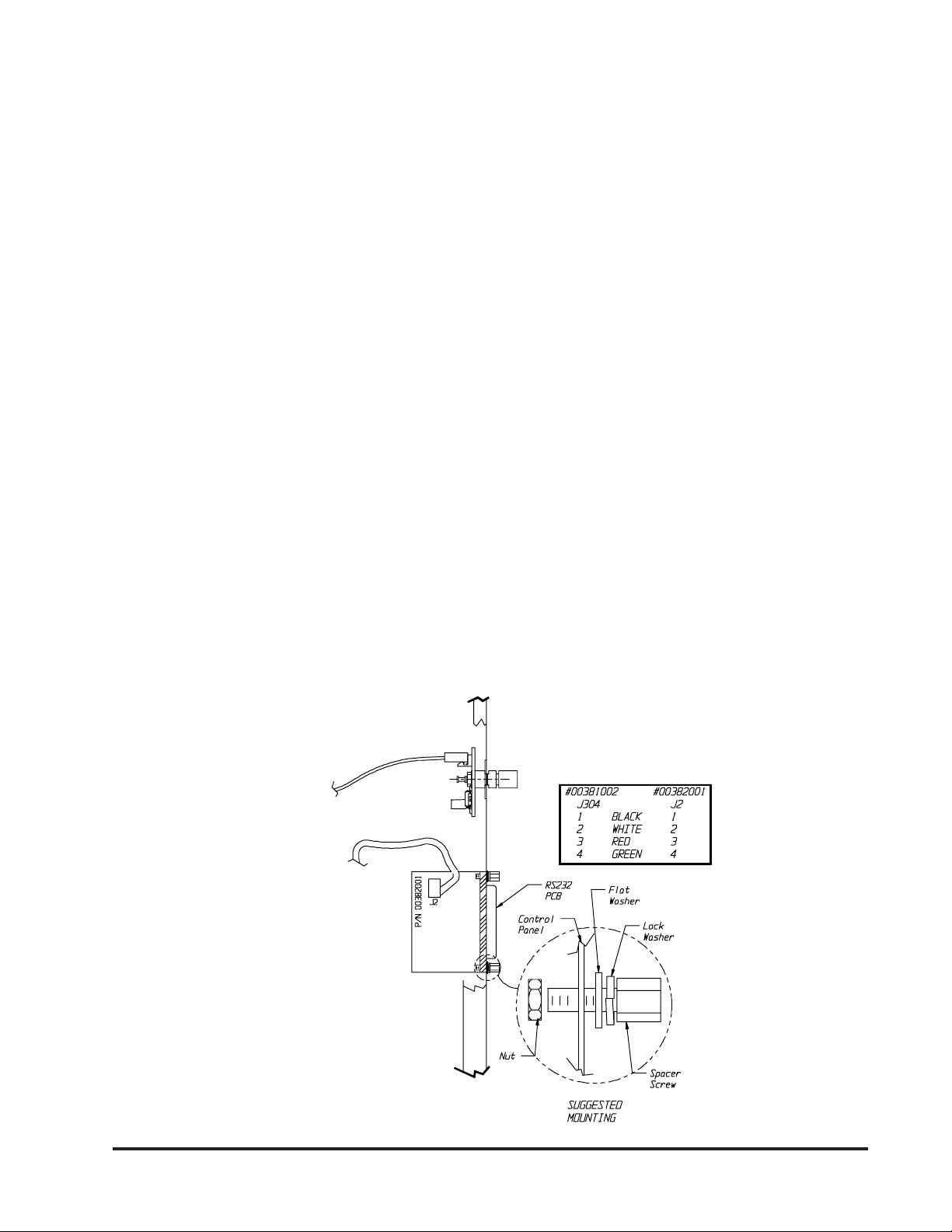
1. Remove the eight (8) screws securing the
control panel. There are four (4) on the top
and 2 on each of the sides. Then remove the
cover by sliding it towards the front of the
incubator.
2. Slide open the auxiliary panel door and locate
the mounting area of the RS232 board as
shown on page 4.
3. Mount the RS232 printed circuit board
assembly using the screws or standoffs
provided. See Figure below.
4. Connect one end of the cable to J304 located
on the left edge of the left printed circuit board
(p/n 34381002). Be careful of alignment.
5. Connect the other end of the cable to the cable
connector on the RS232 PCB assembly (see
sketch).
6. Replace the control panel and secure with the
eight (8) screws.
The RS232 PCB provides a bi-directional
communication port that will allow the user to
monitor the performance or the change the
operating valves of the incubator from a remote
computer. RS232 Communication will require a
communication program such as a modem
program installed in your computer which will allow
the storage of data within your files.
The RS232 PCB utilizes one of the users computer
serial ports, such as COM1 or COM2. The
communication software must be configured to the
selected port. The serial port is an IBM PC AT-
style port. The cable that connects to it must end
in a DB-25 (25-pin) male connector. The cable is
a one-to-one wiring format. The pin assignments
for the serial port are:
PIN SIGNAL DESCRIPTION
2 TXD Serial Transmitted Data
3 RXD Serial Received Data
7 GND Signal Ground (O V)
TOP VIEW OF CONTROL PANEL
To J304
Assy, PCB, 815 CPU
#34381002

14
Setting up the Incubator for Communications
Your Incubator will require the selection of 3
parameters for communications:
A) Baud Rate - This is the speed of
communication between the incubator and
computer. Whatever is selected for the
incubator must also be selected in the
communication software that is planned to be
used.
B) Status Update Time Interval - This is the time
between information being sent from the
incubator to the computer.
C) Status Display Type - Selection of format of
data that is sent to your computer.
Please read the following steps before performing
any of them. It will allow you to familiarize yourself
with the procedure and to determine the values
you want beforehand.
Please note: In the following setup mode there is
a five (5) second time out feature that is active
following each entry. If the five (5) seconds has
been exceeded, the unit will return to the normal
operation mode. If the time out occurs before the
value was entered, start over.
1. With the incubator ON, simultaneously press
and hold the UP and DOWN keys, then press
the ENTER key. The letters will be shown in
the display. A number other than 96 might be
shown in the display:
Choose the number appropriate for the Baud
Rate desired.
3 = 300
6 = 600
12 = 1200
24 = 2400
48 = 4800
96 = 9600
Press the UP or DOWN key until the display
reads your selection. Press ENTER. The baud
rate has been entered.
2. The display should change to the following.
Again, the number in the display might be
different than 0.1, but it will have a decimal
point.
Choose the number appropriate for the Status
Update Time Interval desired.
0.0 Minutes No report
0.1 Minutes Between reports
0.5 Minutes Between reports
1.0 Minutes Between reports
2.0 Minutes Between reports
5.0 Minutes Between reports
10.0 Minutes Between reports
30.0 Minutes Between reports
60.0 Minutes Between reports
Press the UP or DOWN key until the setpoint
display reads your selection. Press ENTER.
The value is entered.
3. The display should have changed to the
following. Again, the number in the display
might be different than 1. This selection is for
Status Display Type.
Listed are the numbered selections with
explanations and examples of the values
displayed on your computer’s monitor when
the incubator transmits information.
0 = Used for a raw, one-line status output
suitable for importing into a spreadsheet.
1 = Used for a multi-line format with English
headings with continuous screen.
2 = Used for the format as “1” but preceded
by a clear screen command used by terminals
or computers running terminal software. This
mode overwrites the previous transmission.
With Status Display Type = 0:
10 -5.0 0

15
Where:
10 = Actual Temperature
-5.0 = Setpoint Temperature
0 = Normal
With Status Display Type = 1 or 2:
Actual Temperature: 10
Setpoint Temperature: -5.0
Alarm Status: Normal
LOW
HIGH
4. Allow the setup to time out.
The incubator is now ready to communicate with
your computer.
Setting up the computer:
Your communications software will most likely have
a setup routine to set the parameters listed below.
These are the values the incubator is using, so
you must match your computers software
parameters accordingly. Also, you will probably
have to select the “COM” serial port you chose
when you connected the cable from your computer
to the incubator. The software may ask what format
the data is in. You should choose “ASCII”.
Parameter Settings
Baud Rate: Baud Rate value selected
earlier in Step 1.
Parity: None (0)
Data Bits: Eight (8)
Stop Bits: One (1)
COM Port: Selected by user
Format: ASCII
Using the Communications:
The incubator transmits information on its RS232
Port as long as the status update time interval is
not “0.0.”
If you start your communication software with the
incubator on, most likely you will see the error(s)
messages as follows:
ERR
? VALUE IS READ ONLY
? ILLEGAL COMMAND
Wait for the Status Update Time duration you
selected to complete, and the communications will
correct itself.
Besides having the incubator transmit information
in one of the three formats, the user can monitor
other values or even change some of these from
their computer.
The following table lists the available commands
for monitoring or controlling your unit.
To View Data: If Status Update Time is “0.0” no
data will automatically be displayed. To view data
within a particular command code, type that
command code followed by the question mark (?)
symbol and then ENTER (Return).
Example: To view Setpoint Temperature type:
T? <CR>
View
Command: Description: Unit: Range: Change
Command
A? Actual Temperature Degrees -10 to 50 Read Only
T? Setpoint Temperature Degrees -10 to 50 T10 thru T50
R? Baud Rate -0 - 5 R0 thru R5
S? Status Update Time -0 - 8 S0 thru S8
V? EPROM Version Number -Current Rev. Read Only
D? Status Display Type -0 - 2 D0 thru D2
O? Display the Alarm Status -0 - 2 Read Only

16
To Change Data: To change the value within the
command type the command code followed by the
new value and ENTER (Return).
Example 1: To change Setpoint Temperature to
25.0°C type:
T25.0 <CR>
Example 2: To change Setpoint Temperature to -
.8°C type:
T-.8<CR>
(A) Actual Temperature: The actual
temperature within the incubator.
(T) Setpoint Temperature: The temperature at
which the user has selected the incubator
to operate.
(R) Baud Rate: The rate at which data is
transmitted between the incubator and your
computer
0 = 300 Baud
1 = 600 Baud
2 = 1200 Baud
3 = 2400 Baud
4 = 4800 Baud
5 = 9600 Baud
(S) Status Update Time Interval: The time
between data messages sent from the
incubator to your computer
0 = 0 Minutes, No report
1 = 0.1 Minutes (6 seconds)
2 = 0.5 Minutes (30 seconds)
3 = 1.0 Minutes
4 = 2.0 Minutes
5 = 5.0 Minutes
6 = 10.0 Minutes
7 = 30.0 Minutes
8 = 60.0 Minutes
(V) EPROM Version Number: The incubator
software version level.
(D) Status Display Type: Selection of format
that data is sent to your computer
0 = Used for a raw, one-line status output
suitable for importing into a spreadsheet
1 = Used for a multi-line format with English
headings
2 = Used for the format as “1” but preceded
by a clear screen command used by
terminals or computers running terminal
software.
(O) Display the Alarm Status: The alarm
has thee (3) possible values:
0 = Normal, no alarms
1 = Low alarm
2 = High alarm
Table of contents
Other Precision Accessories manuals


