POL-EKO SMART ILP 53 User manual

Laboratory incubators
with a cooling system based on Peltier effect
models: ILP 53, ILP 115, ILP 240, ILP 750
Before using the equipment, please read carefully this instruction manual!
Version 1.25
Issued 18.01.2022
Instruction manual SMART

Instruction manual ILP SMART
2
Manufacturer's address:
POL-EKO-APARATURA sp. j.
ul. Kokoszycka 172 C
44-300 Wodzisław Śląski
Country of origin: Polska
As a manufacturer, we inform you that we took the necessary measures to ensure that this device fully meets your
expectations and is reliable for a long period of use. Due to the continuous improvement of our products, as well as the
expansion of our offer, any suggestions regarding additional functions and equipment functioning are welcome. Visit
our homepage www.pol-eko.com.pl/home-en/
Equipment disposal
This equipment is marked with the crossed out wheeled bin symbol to indicate that this equipment must not be dis-
posed of with unsorted waste. Instead it's your responsibility to correctly dispose of your equipment at lifecycle -end by
handling it over to an authorized facility for separate collection and recycling. It's also your responsibility to
decontaminate the equipment in case of biological, chemical and/or radiological contamination, so as to protect from
health hazards the persons involved in the disposal and recycling of the equipment. For more information about where
you can drop off your waste of equipment, please contact your local dealer from whom you originally purchased this
equipment.
By doing so, you will help to conserve natural and environmental resources and you will ensure that your equipment is
recycled in a manner that protects human health.
Thank you!

Instruction manual ILP SMART
3
Contents:
1. INTENDED USE AND IMPORTANT INFORMATION FOR THE USER.........................................................5
2. PACKAGE CONTENTS..................................................................................................................................6
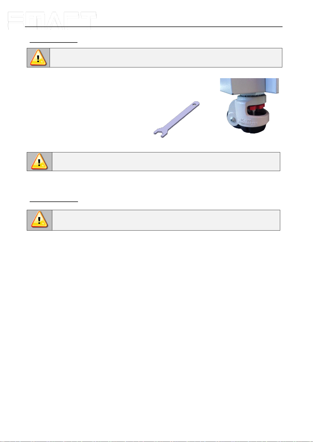
3. BEFORE THE FIRST USE..............................................................................................................................6
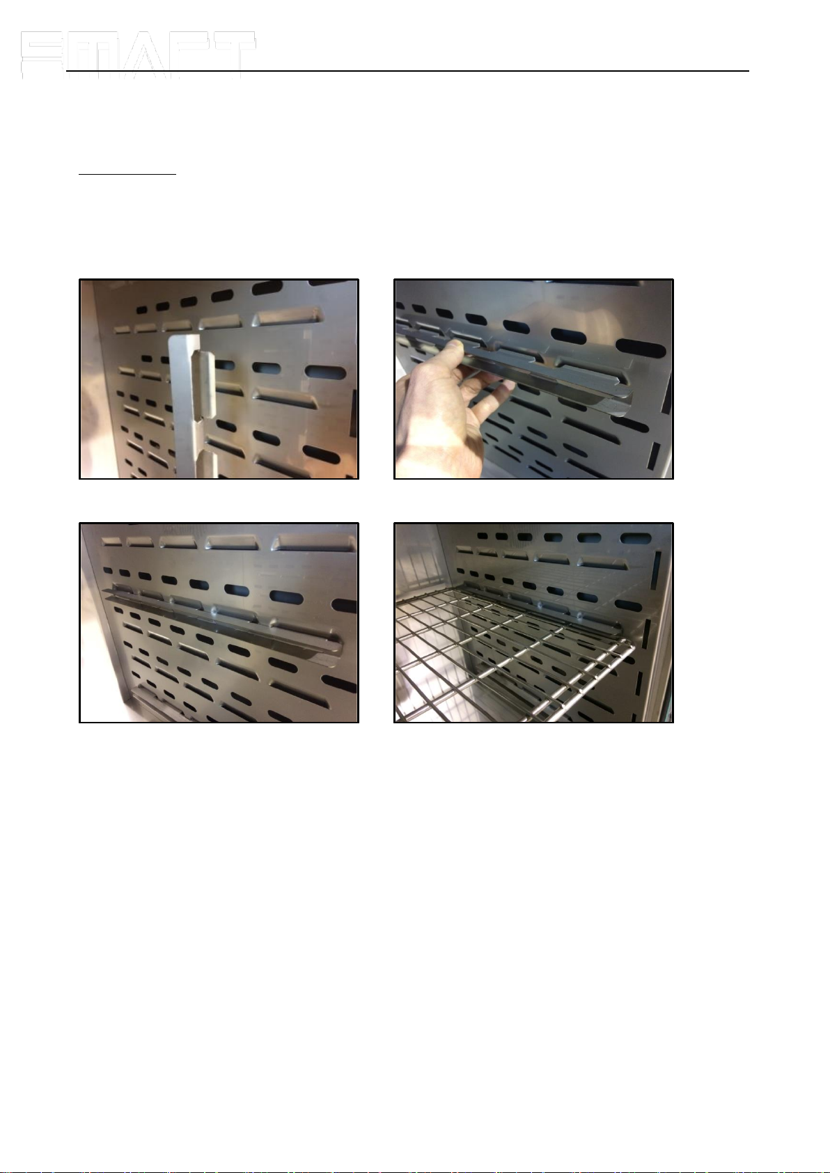
3.1. Installation of shelves .............................................................................................................................8
3.2. Condensation in the chamber.................................................................................................................9
3.3. Remarks on the placement of samples...................................................................................................9
3.4. Closing chamber door.............................................................................................................................9
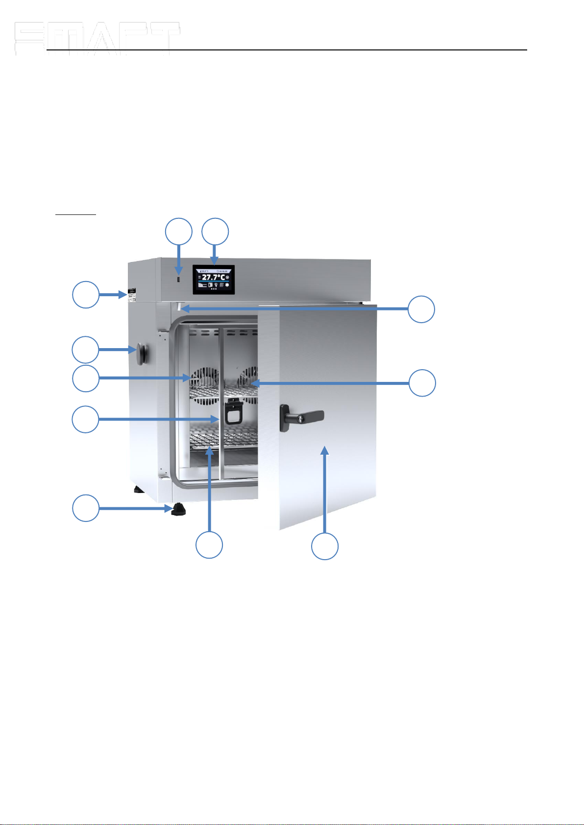
4. DESCRIPTION OF THE DEVICE..................................................................................................................10
4.1. Design of ILP devices...........................................................................................................................10
5. DEVICE EQUIPMENT (standard and optional)..........................................................................................12
5.1. Internal glass door (standard)...............................................................................................................12
5.2. External door with viewing window (optionally).....................................................................................12
5.3. Internal socket (optionally)....................................................................................................................12
5.4. Door lock (standard).............................................................................................................................13
5.5. Access port for external sensor (standard)...........................................................................................13
5.6. Open door alarm (standard) .................................................................................................................13
5.7. Internal LED light (optionally)................................................................................................................14
5.8. USB port (standard)..............................................................................................................................14
5.9. Display battery backup (optionally).......................................................................................................15
6. DEVICE OPERATION...................................................................................................................................15
6.1. External memory (USB flash drive).......................................................................................................15
6.2. First boot...............................................................................................................................................15
6.3. Main screen.................................................................................................................................16
6.3.1. Information panel..............................................................................................................................17
6.3.2. The meaning of icons and symbols..................................................................................................20
6.3.3. Upper menu......................................................................................................................................21
6.3.4. Alarm bar..........................................................................................................................................23
6.4. Quick Program......................................................................................................................................23
6.5. Programs.....................................................................................................................................25
6.5.1. Creating / editing a program.............................................................................................................26
6.5.2. Segments edition..............................................................................................................................27
6.5.3. Summary of segments......................................................................................................................28
6.5.4. Protection class................................................................................................................................29
6.5.5. Temperature protection (option).......................................................................................................29
6.5.6. Priority..............................................................................................................................................30
6.5.7. Loop .................................................................................................................................................30
6.5.8. Defrosting program...........................................................................................................................30
6.6. Starting the program.............................................................................................................................31
6.6.1. The first way.....................................................................................................................................31
6.6.2. The second way...............................................................................................................................32
6.7. Quick Change of parameters................................................................................................................33

Instruction manual ILP SMART
4
6.7.1. Quick change of set temperature .....................................................................................................33
6.7.2. Quick change of set time..................................................................................................................34
6.8. Statistics ......................................................................................................................................35
6.9. Data record..................................................................................................................................36
6.10. Event log .....................................................................................................................................37
6.11. Info ..............................................................................................................................................39
6.12. User settings panel......................................................................................................................40
6.12.1. Unlocking the touch screen..............................................................................................................41
6.13. Time ............................................................................................................................................41
6.14. Alarms.........................................................................................................................................42
6.14.1. Mute option.......................................................................................................................................43
6.15. Network.......................................................................................................................................44
6.16. Corrections...................................................................................................................................45
6.17. Archives.....................................................................................................................................45
7. INTERFACE..................................................................................................................................................46
7.1. MODBUS TCP......................................................................................................................................46
8. TEMPERATURE PROTECTION...................................................................................................................47
8.1. Temperature protection class ...............................................................................................................47
9. CONNECTING THE DEVICE TO A COMPUTER.........................................................................................47
10. OPERATION OF THE COOLING SYSTEM..................................................................................................47
11. CLEANING AND MAINTENANCE OF THE DEVICE...................................................................................48
11.1. Exterior cleaning...................................................................................................................................48
11.2. Interior cleaning....................................................................................................................................48
11.3. Cleaning the touch screen....................................................................................................................49
11.4. Consumables........................................................................................................................................50
12. ADVICE ON HOW TO SAFELY STORE THE DEVICE................................................................................50
13. TROUBLESHOOTING..................................................................................................................................50
13.1. Possible defects....................................................................................................................................51
14. WARRANTY CONDITIONS..........................................................................................................................52
15. RATING PLATE............................................................................................................................................53
16. TECHNICAL DATA.......................................................................................................................................54
17. DECLARATION OF CONFORMITY .............................................................................................................55

Instruction manual ILP SMART
5
1. INTENDED USE AND IMPORTANT INFORMATION FOR THE USER
ILP incubators are laboratory devices designed for incubation and storage of samples at temperature range from 0°C
to +70°C (maximum 20°C below ambient temperature). Incubators have both heating and cooling system based on
Peltier modules and forced air convection.
The meaning of information symbols
This symbol means that failure to follow the instructions could endanger people's health or life, or
damage the device. The manufacturer is not liable for damages resulting from non-compliance with
the instructions contained in the manual.
This symbol indicates helpful tips.
To guarantee your security and the longevity of the unit, please comply with the following rules:
1.
The unit cannot be installed:
•outside,
•in damp places or places which can be easily flooded,
•near flammable or volatile substances,
•near acids or in corrosive environments.
2.
It is forbidden to:
•store inflammable or volatile substances inside the unit,
•touch live parts of the unit,
•operate the unit with wet hands,
•put water vessels on the unit,
•climb on the unit,
•overload the shelves (the maximum load is described in technical data).
3.
You should:
•place samples in such a way to provide proper air circulation in the chamber,
•open the door for the shortest period of time to reduce temperature fluctuations,
•secure samples from being blown out by the chamber fan e.g powdery samples,
•always check that the doors are closed correctly,
•use only mains with earth to avoid electric shocks,
•unplug the power cable holding the protective cover and not the cable itself,
•disconnect the unit from the mains before undertaking any repairs or maintenance work (in order to not
lose the warranty during its duration, all repairs should be carried out by an authorized service),
•protect the power cable and the plug from any damage,
•disconnect the power plug before moving the unit,
•disconnect the power plug if the device will not be used for a long period of time,
•disconnect the unit and protect it from reconnecting if it has any visual fault.
Failure to comply with the above recommendations may result in damage to the device or deterioration of
technical parameters, as well as loss of warranty.

Instruction manual ILP SMART
6
2. PACKAGE CONTENTS
Incubators with Peltier modules (ILP) in SMART version are delivered with:
3. BEFORE THE FIRST USE
The manufacturer sends the device protected by cardboard profiles and foil. The device should be transported in an
upright position and the package should be secured against sliding during transport.
After transporting the device at a temperature below 10°С, wait at least 2 hours before connecting it
to the mains.
On the surface of unit’s components made of stainless steel, slight discoloration may occur. It is a result of the
technologies used in the production of metal sheet in accordance with the requirements of PN-EN 10088-2 standard
and it is not a defect of the unit.
The place of installation of the unit should meet the following conditions:
•ambient temperature +10°C...+28°C, for models with glass door +10°C...+25°C,
•recommended relative humidity of the ambient air up to 60%,
•the unit has not been designed to work in highly dusty environments,
•ensure proper ventilation in the room,
•the device should be placed on a hard and stable surface,
•the unit should be placed at least 100mm away from the walls,
•the height of the room must be at least 300mm greater than the height of the unit,
•the unit is not designed to be built-in,
•the place of installation of the device should be equipped with a socket with parameters suitable for the
device.
If you don’t comply with the above recommendations, the unit may get broken or it may worsen the technical
parameters such as:
•temperature fluctuation,
•temperature variation,
•power consumption,
and may result in loss of warranty.
Device
ILP
Capacity
53
115
240
750
Shelves [pcs.]
2
2
3
5
Slides [pcs.]
4
4
6
10
Power cord [pcs.]
1
1
1
1
Rubber cap [pcs.]
1
1
1
1
Key for door lock [pcs.]
2
2
2
2
Wrench (13mm) for wheels adjustment [pcs.]
x
x
x
1
Quality Control Certificate [pcs.]
1
1
1
1
After receiving the device, visually assess its condition and equipment in the presence of the
person delivering the goods. A courier company is responsible for any damage caused during
transport.

Instruction manual ILP SMART
7
Wheels / leveling feet
The device has been equipped with wheels or leveling feet. After placing the unit at its destination,
secure the device against movement by locking the wheels. In the case of feet, after placing the
device in the destination, they should be leveled.
If the device is equipped with wheels, they must be locked and leveled (wheels in ILP
750 can be leveled). For this purpose use the red knob mounted in the wheel housing.
At the beginning, the knob can be turned by hand, if it encounters resistance, use a 13
size wrench.
If the device is to be placed on a table (option) or base (option) which is equipped with the wheels with a lock, the
wheels MUST be locked after placing the table / base in its final destination.
Electric installation
Power supply of the equipment is indicated on a rating plate on the unit. Connect the device to a
socket with ground in order to avoid electric shocks in case of the unit’s failure.
The installation should be protected by a 16A slow-blow fuse and equipped with a residual current device.
Leveling wheels are ONLY for positioning the device at its destination. They can not be used to
transport the device!

Instruction manual ILP SMART
8
3.1. Installation of shelves
In the ILP models
To install the shelf or to change its position, follow these steps:
Install the shelf slide at the selected height by inserting it into perforations on the wall of the device. Do the same with
the slide on the opposite wall.
Slide the shelf into the installed shelf slides. Now, the shelf is correctly installed!
To remove a shelf, perform the above steps in reverse order.

Instruction manual ILP SMART
9
3.2. Condensation in the chamber
If the set temperature is much lower than the ambient temperature, condensation may occur, which will cause
accumulation of the water at the bottom of the chamber. The amount of accumulated water depends on the following
factors:
•the difference between the ambient temperature and the temperature in the chamber,
•frequency of door openings,
•temperature of the samples.
Too high relative humidity in the chamber can cause icing of the cooling element, and thus reduce the
cooling efficiency and increase power consumption.
Cartons, sponges and other hygroscopic materials should not be used to store samples, as they may increase the
humidity in the chamber.
3.3. Remarks on the placement of samples
To provide proper air circulation and stable conditions in which the samples are stored in the chamber, it is necessary
to keep the following rules:
•the max height of the samples should not exceed 1/3 of the space between the shelves,
•approx. 1/3 of the width and depth of the shelf should remain empty, while the distances between the
samples, as well as between the samples and the wall should be approximately equal.
The picture below is an example of the placement of samples in the chamber.
Hmax
H
Hmax
a
uv w
xy z
b
u+v+w > 1/3 a
x+y+z > 1/3 b
Hmax = 2/3H
u v w
x y z
H
≅
≅ ≅
≅
Front view
Top view
Shelf
Following the above rules will provide best optimal parameters of temperature fluctuation and variation.
3.4. Closing chamber door
All ILP incubators have been equipped with a gasket and open door sensor. If the door has not been closed properly,
an audible and visual alarm will start. You can set delay door alarm by: 30s, 1 min, 2 min, 5 min or 10 min (see Section
6.14).
If water accumulates at the bottom of the chamber, wipe the bottom of the chamber with a dry cloth.

Instruction manual ILP SMART
10
4. DESCRIPTION OF THE DEVICE
SMART models are equipped with a PID microprocessor temperature controller and a 4.3 inch colour touch screen with
a resolution of 800x480.
4.1. Design of ILP devices
Below there’s a picture of ILP 53 model (exemplary photo) with a description of the important components of the
device.
Front view
1) rating plate
2) access port ø30mm for external
sensor
3) temperature sensor
4) internal glass door
5) adjustable feet
6) inox wire shelf
7) external solid door
8) Peltier module chamber fan
9) open door sensor
10) touch control panel
11) USB port
2
5
6
8
11
7
4
3
10
9
1

Instruction manual ILP SMART
11
Rear view
1) main switch
2) spacer frame
3) external fans of the Peltier module
4) LAN port
5) fuse
6) main power socket c20
6
5
4
3
2

Instruction manual ILP SMART
12
5. DEVICE EQUIPMENT (STANDARD AND OPTIONAL)
5.1. Internal glass door (standard)
Internal glass door is a standard equipment in ILP cooled incubators. To open and
close the door use the plastic handle attached to the glass.
During operation, when the temperature inside the chamber is high, do not touch the internal
components and glass doors, as there is a risk of burns. Use protective gloves to protect yourself
against the effects of burns from hot components.
5.2. External door with viewing window (optionally)
The external door with a viewing window is an optional equipment for ILP cooled incubators.
During operation, when the temperature inside the chamber is high, do not touch the internal
components and glass doors, as there is a risk of burns. Use protective gloves to protect yourself
against the effects of burns from hot components.
5.3. Internal socket (optionally)
An internal socket with grounding and IP44 protection is an optional equipment
for ILP incubators. The internal socket (depending on the model: 230V 50Hz /
230V 60Hz / 115V 60Hz) is intended for EU plugs or plugs type B. The socket
can be used to connect electrical devices inside the device.
We do not recommend installing and removing internal glass door. Incorrect assembly or disassembly may
result in damage to the glass and injury to the User.
The maximum permissible load of all sockets inside the device (max. 3 pcs.) is 200 [W].

Instruction manual ILP SMART
13
Always make sure that the safety rules for working with electrical devices are followed!
5.4. Door lock (standard)
All devices have a key lock. The key lock is situated in the door handle. Two keys are supplied with the device (hung
on the back of the device).
5.5. Access port for external sensor (standard)
A Ø30 mm access port can be used to insert an external temperature sensor for independent temperature control
inside the device. The access port has been secured with a rubber plug. The plug should cover the access port while
the unit is operating. If multiple cables have been inserted through the access port and it is not possible to use the plug,
secure the access port with adhesive tape. If you leave the access port open, it may affect temperature fluctuation and
variation inside the chamber.
5.6. Open door alarm (standard)
All units have been equipped with an open door sensor. If you open the door, the icon: will appear (the number
above the icon presents open door counter. Press the icon to cancel the counter. The counter is also cancelled by
turning of the device). If the door remains open longer than the time set by the user (30s, 1 min, 2 min, 5 min, 10 min)
an acoustic signal, red pulsating alarm bar and „open door” alarm with active status will appear.
Open door sensor

Instruction manual ILP SMART
14
5.7. Internal LED light (optionally)
All ILP incubators can be optionally equipped with LED interior lighting integrated with an open door sensor (Philips
Corepro LEDspot 3.5-35W GU10 827 36D). When the light switches on, the icon . will appear on the display. For
devices with door with viewing window, pressing the icon allows you to turn the LED light ON or OFF (the light-
ing is not integrated with the open door sensor).
5.8. USB port (standard)
The USB port on the front panel is used only to transfer data from the device's internal memory to the flash drive. To do
this insert the flash drive into the USB port on the front panel and then:
•go to the main menu ,
•go to the data record ,
•press and choose type of the file: *.csv, or *.plkx.
•press . Data has been copied.
After copying the data to the USB flash drive, before removing it from the USB socket, it should be unmoun-
ted by pressing the icon in the top drop-down list (Figure 1). If the pendrive is not unmounted after
connecting to the computer, a message about pendrive damage may be displayed with a repair proposal,
when actually the pendrive is not damaged
Figure 1 Unmounting USB flash drive

Instruction manual ILP SMART
15
Data saved in the * .csv file can be opened in a spreadsheet. Data saved as * .plkx can be opened in the Lab Desk
program (additionally paid option). This program allows, among others, for data preview in the form of a table or a
graph. It also allows you to prepare a statistic report for a selected range of data. For more information see Section 6.1.
5.9. Display battery backup (optionally)
Units in the SMART version can be optionally equipped with a battery backup of the display. The power loss and
switching to the battery backup display mode is signaled by a pulsating red frame around the display and a sound
signal (if it is turned on). In the battery backup display mode, all parameters are displayed, ie temperature. Other
alarms, e.g. exceeding the temperature range, are also signaled.
In order to extend the battery life, the display is dimmed all the time. Batteries are automatically charged in AC mode.
6. DEVICE OPERATION
This symbol means that a given window can be moved in the direction shown in the picture.
6.1. External memory (USB flash drive)
The external memory (USB flash drive) allows to copy: instruction manual, data record, event log and service log from
the device memory. Before first use the USB flash drive should be formatted in the FAT 32 file system. Insert the
device in the USB slot on the front of the device next to the display. Wait a few seconds, the correct reading is
indicated by the message „USB flashdrive connected” at the bottom of the screen.
6.2. First boot
During the first boot, the screen (Figure 2) will display information about saving the "Download" folder (with instruction
manual in pdf format) on the USB flash drive. In order to do it, insert the USB flash drive and wait a second to detect
the hardware, then press .
If you press you quit downloading the folder. The window will appear again during the next boot. You can tick
„Don’t show again” so that the window will not be displayed after switching on the device. You can always download
the „Download”folder in the Info submenu. More information Section 6.11.
After copying the data to the USB flash drive, before removing it from the USB socket, it should be unmoun-
ted (see Section 5.8.).
USB slot is used to connect only a flash memory –a pendrive or a card reader with a memory card.
Connecting any other device (e.g. external hard drive) without consultation is not authorized by the
manufacturer and may damage the USB slot.

Instruction manual ILP SMART
16
Figure 2 Downloading files
6.3. Main screen
After switching on the device, the main screen (Figure 3) appears. It contains the information about the device status.
After starting the program, additional information appears on the screen (Figure 4).
Figure 3 Main screen

Instruction manual ILP SMART
17
Figure 4 Main screen –running program
6.3.1. Information panel
There are two different windows in the information panel. Switching between them is done by swiping the finger left or
right.
Figure 5 Information panel
The icon indicates information about which window is active.
current
temperature
in the
chamber
(main sensor)
side-scrolling
information
panel
alarm bar
set
temperature
main
menu
start/stop
program
turning off alarm
sound
segment
duration time
program
status
active
panel
current
date/hour

Instruction manual ILP SMART
18
6.3.1.1. Alarms panel
The icon which is on the second page of the information panel, allows you to go to the alarms panel.
Figure 6 Icon: Alarms panel
In the alarms panel (Figure 7) there’s a list with active alarms or the alarms that have occurred but have not been con-
firmed. When the alarm is active, the alarm bar is red and the alarm event is displayed in the list with the status "active".
When the alarm event stops, the state changes to "inactive".
•“delete” button – confirms and removes the alarm from the list (only inactive alarms can be deleted),
•“confirm” button – confirms an alarm,
•“details” button – displays a preview of all instances of selected alarm (Figure 8).
Figure 7 Alarms panel
Figure 8 Alarm details

Instruction manual ILP SMART
19
The icon which is on the second page of the information panel, allows you to go to the status panel.
Figure 9 Icon: Status panel
The status of the device is indicated also by description.
Figure 10 Status –description
6.3.1.2. Status panel
program name
the name of running program
current segment
currently running segment / total number of segments in the program
priority
of time or parameters
time set
set time of running segment
time elapsed
elapsed time since the segment has started
time remaining
remaining time until the end of the segment
current loop
currently performing cycle/ total number of cycles to perform
protection class
over temperature
under temperature
information about the protection temperature of a running or completed program. The
protection parameters can be set in the program parameters. Information about protection
classes
upper alarm temp
lower alarm temp
information about set alarms, separately for upper and lower alarm temperature. Setting of
the alarms

Instruction manual ILP SMART
20
6.3.2. The meaning of icons and symbols
The icon allows you to go to the main screen.
Automatic return to the home screen. Factory setting: disabled.
The icon allows you to go to the main menu.
Automatic screen lock. Factory setting: disabled.
Unmounting the USB flash drive before removing it from the USB socket.
Internal light is switched on. The icon appears when the incubator is optionally
equipped with internal light (OWW). Light switched off –icon is inactive. By clic-
king the icon on the status panel you can manually turn on / off the light
(applies to devices with the door with viewing window).
Closed door, open door. The number above the icon presents open door counter.
Press the icon to cancel the counter. The counter is also cancelled by turning of
the device.
Fan icon. Rotating icon means that the program is active. If it is not rotating –the
program is inactive.
Ramp status: Chamber is currently heating up or cooling down.
Set temperature is reached.
The program will start on the given date / time.
Start delay activated.
Icon is visible only when the chamber is cooling down.
Icon is visible only when the chamber is heating up.
Available when the program is running Clicking the icon allows you to quickly
change the set temperature (Quick Change function).
When the program is running, click the icon to quickly change the time of
program duration (Quick Change function).
Indicates the time that has elapsed from the program start.
Countdown of the time remaining to the end of the program.
.
The arrow icon allows navigation between: segments, program parameters and
summary.
Other manuals for SMART ILP 53
1
This manual suits for next models
3
Table of contents
Other POL-EKO Accessories manuals