Precision WRDLW484K30L User manual

2
Table of Contents
Safety Information.....................................................2
Warranty.....................................................................2
Pre-Installation..........................................................3
Planning Installation ..............................................3
Tools Required .......................................................3
Hardware Included.................................................3
Package Contents ..................................................3
Junction Box Installation ..........................................4
Keyhole Installation...................................................6
Care and Cleaning .....................................................9
Troubleshooting .........................................................9
Safety Information
WARNING: Carefully read and understand this manual
before beginning the assembly and installation. Failure
which could be hazardous or even fatal.
WARNING: Before beginning the installation,
disconnect the power to the circuit by turning off the
circuit breaker or removing the fuse.
WARNING:
requires a person familiar with the construction and
IMPORTANT:
approved by the party responsible for compliance could
void the user’s authority to operate the equipment.
NOTICE: This equipment has been tested and found to comply with
the limits for a Class B digital device, pursuant to Part 15 of the FCC
Rules. These limits are designed to provide reasonable protection
against harmful interference in a residential installation. This equipment
generates, uses and can radiate radio frequency energy and, if not
installed and used in accordance with the instructions, may cause
harmful interference to radio communications.
However, there is no guarantee that interference will not occur in a
particular installation. If this equipment does cause harmful interference
to radio or television reception, which can be determined by turning
the equipment off and on, the user is encouraged to try to correct the
interference by one or more of the following measures:
�Reorient or relocate the receiving antenna.
�Increase the separation between the equipment and the receiver.
�Connect the equipment into an outlet on a circuit different from
that to which the receiver is connected.
�Consult the dealer or an experienced radio/TV technician for help.
Warranty
WHAT IS COVERED
products used in normal use and service. If this product is found to be defective, the manufacturer’s only obligation,
and your exclusive remedy, is the repair or replacement of the product at the manufacturer’s discretion, provided
mishandling.
WHAT IS NOT COVERED
This warranty shall not apply to any product that is found to have been improperly installed, set-up, or used in any
way not in accordance with the instructions supplied with the product. This warranty shall not apply to a failure of
the product as a result of an accident, misuse, abuse, negligence, alteration, faulty installation, or any other failure
product, such as surface and/or weathering, as this is considered normal wear and tear.
liability and shall not be liable for any consequential or incidental loss or damage, including but not limited to any
labor / expense costs involved in the replacement or repair of said product.
Contact the Customer Service Team at 1-877-527-0313 or visit www.HomeDepot.com.
FCC responsible party :
Precision Consumer Products Group, LLC.
11024 Balboa Boulevard Suite 1710 Granada Hills, CA 91344
1-866-237-9983
3
Pre-Installation
PLANNING INSTALLATION
Before beginning assembly, installation, or operation of the product, make sure all parts are present. Compare parts
with the package contents list. If any part is missing or damaged, do not attempt to assemble, install, or operate the
product. Contact customer service for replacement parts.
NOTE: Keep your receipt and these instructions for proof of purchase.
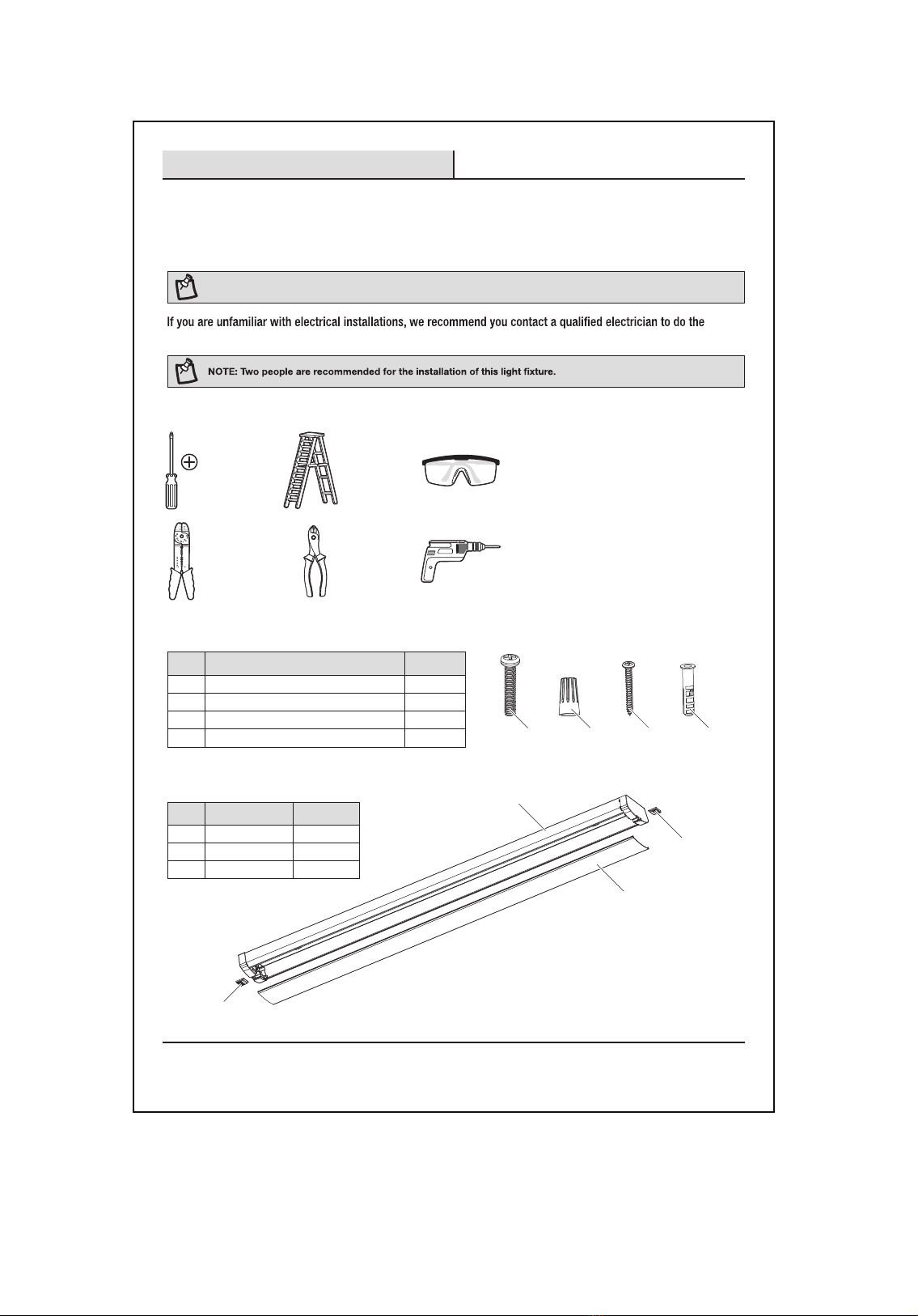
installation.
TOOLS REQUIRED
Phillips
screwdriver Ladder Safety
glasses
Wire
strippers
Wire
cutters
Power drill
with drill bits
HARDWARE INCLUDED
Part Description Quantity
AA BB CC DD
AA Phillips head junction box machine screws 2
BB Wire nuts 1
CC Phillips head wood screws 4
DD Dry wall anchors 4
PACKAGE CONTENTS
Part Description Quantity
A Fixture 1
B Lens 1
C Lens access tabs 2
A
B
C
C

4
Pre-Installation (continued)
before drilling.
WARNING: RISK OF ELECTRIC SHOCK. Ensure the electricity to the wires you are working on is shut off. Either remove the fuse or
CAUTION: Before beginning installation turn off the circuit breaker and light switch.
Junction Box Installation
1 Installing the screws
�Install the two screws (AA) into the junction
box (1).
NOTE: Leave 1/4" of screw thread exposed to
AA
1
2 Removing the lens
�
sliding the lens access tabs (C) out from the end
�Gently lift and remove the lens (B) from where
the lens access tab was removed.
A
B
C
3 Removing the knockout
�
cables through the knockout hole.
A1
5
Junction Box Installation (continued)
4 Wiring the fixture
�Before wiring, temporarily connect the male
and female quick connectors (1) to determine
the placement of the black and white power
supply wires. Then, separate the quick
connectors. At the junction box, push the
black power supply wire into the connection
slot on the male quick connect on the side
that will marry to the black side of the female
quick connect. Push the white wire into the
remaining slot.
�
from the end of the green wires in order to
expose the copper wires. Twist the green wire
to the corresponding ground wires (GREEN to
GREEN) in the junction box and secure using
the included wire nut (BB).
�Reconnect the male and female quick
�OPTIONAL: Wrap connected wire nuts with
electrical tape.
BB
A
1
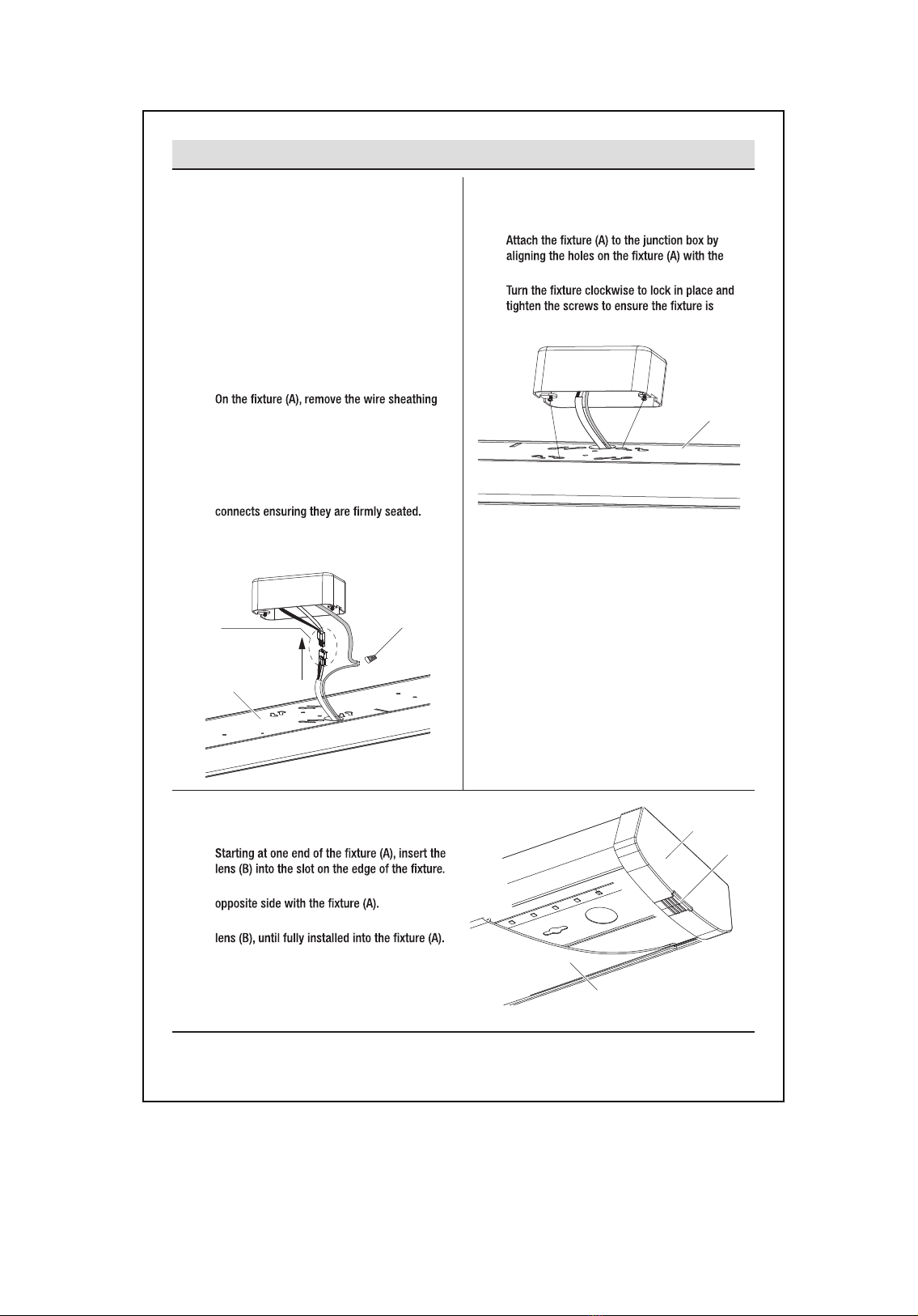
5 Attaching the fixture
�
screws on the junction box.
�
secure and will not move.
A
6 Attaching the lens
�
�Carefully squeeze the lens (B) to engage the
�Continue this action down the length of the
�Replace the lens access tabs (C).
A
C
B
6
Keyhole Installation
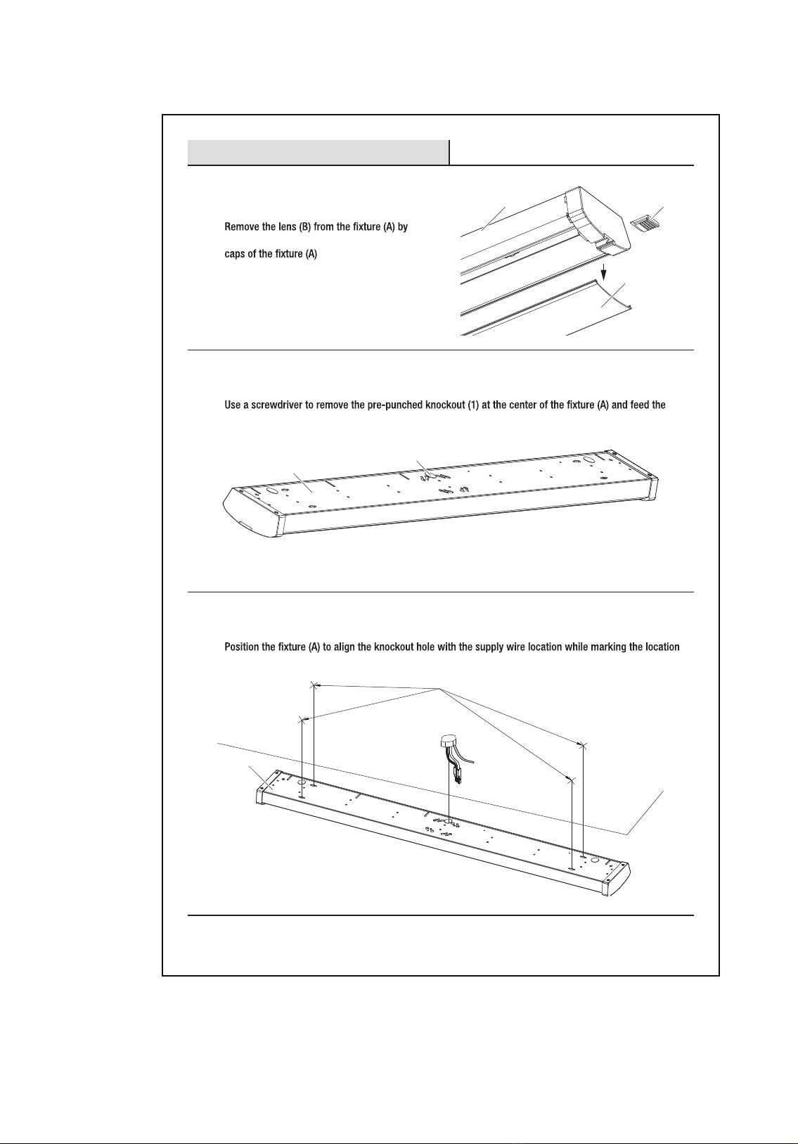
1 Removing the lens
�
sliding the lens access tabs (C) out from the end
�Gently lift and remove the lens (B) from where
the lens access tab was removed.
A
B
C
2 Removing the knockout
�
cables through the knockout hole.
A1
3 Positioning the fixture
�
of the four keyhole slots at each end of the housing.
Mark these locations
(mounting surface)
A

7
Keyhole Installation (continued)
4 Mounting the fixture through
drywall
�If the mounting holes go through drywall
without a stud, drill a small pilot hole with
1/8” drill bit (not included) and install wall
anchors (DD) into the holes with a hammer
(not included). Install the four wood screws
(CC) into the mounting surface, leaving an
approximate 3/8” gap between the screw head
and the mounting surface.
Drywall
DD
CC
5 Mounting the fixture to a wall
stud
�If the mounting holes align with wall studs,
drill a pilot hole using a 5/32” drill bit (not
included) for the wood screws (CC).
�Install the four wood screws (CC) into the
mounting surface leaving an approximate 3/8”
gap between the screw head and mounting
surface.
Wall stud
CC
6 Connecting the wires
�Before wiring, temporarily connect the male
and female quick connectors (1) to determine
the placement of the black and white power
supply wires. Then, separate the quick
connectors. At the junction box, push the
black power supply wire into the connection
slot on the female quick connect on the side
that will marry to the black side of the male
quick connect. Push the white wire into the
remaining slot.
�
from the end of the green wires in order to
expose the copper wires. Twist the green wire
to the corresponding ground wires (GREEN to
GREEN) in the junction box and secure using
the included wire nut (BB).
�Reconnect the male and female quick
�OPTIONAL: Wrap connected wire nuts with
electrical tape.
BB
A
1

8
Keyhole Installation (continued)
7 Attaching the fixture
�Hide the wires in the junction box and guide the heads of the four wood screws (CC) into the keyhole
slots.
�
�
to the mounting surface.
CC
8 Attaching the lens
�
�
�
�Replace the lens access tabs (C).
A
C
B

9
Model Specification Brand
CTCL-153PLUTRON 120V,60Hz,150WCFL/LED,600W/Incandescent
DVCL-153PLUTRON 120V,60Hz,150WCFL/LED,600W/Incandescent
MACL-153PLUTRON 120V,60Hz,150WCFL/LED,600W/Incandescent
LG-600PLUTRON 120V,60Hz,600W/Incandescent
TG-600PLUTRON 120V,60Hz,600W/Incandescent
DV-600PLUTRON 120V,60Hz,600W/Incandescent
S-600PLUTRON 120V,60Hz,600W/Incandescent
These fixtures are fully dimmable using a standard household LED rated dimmer.
THEY DO NOT REQUIRE A SPECIAL 0-10V DIMMER. If connecting a dimmer,
please use the instructions provided with that device.
Compatible standard dimmers
Operation
�Turn on power at the circuit breaker or fuse box.
�
Care and Cleaning
�
�Do not use any cleaners with chemicals, solvents, or harsh abrasives. Use only a dry, soft cloth to dust or wipe carefully.
Troubleshooting
Problem Solution
The light will not turn on. Ensure the power supply is on.
Test or replace the wall switch.
Check the wiring.
The fuse blows or circuit breaker trips when the light is turned on. Check the wire connections.

This manual suits for next models
1
Table of contents
Popular Lighting Equipment manuals by other brands


Federal Signal Corporation
Federal Signal Corporation ILSFFVHL-CH08 installation instructions

IDEAL INDUSTRIES
IDEAL INDUSTRIES CREE LIGHTING DOT Series quick start guide

Star Headlight & Lantern
Star Headlight & Lantern Contour S-Link System 9100DLED DUAL-COLOR... manual

Eaton
Eaton Crouse-hinds series Operating instruction

Satco
Satco NUVO 67-102 Installation and safety instructions

lap
lap 50697 Installation and safety instructions