PRECITEC CHRocodile C User manual
1
CHRocodile C
Compact sensor for non-contact distance and thickness measurement
Operation Manual

2
Imprint
This documentation is under the copyright of Precitec Optronik GmbH.
It may not be reproduced or used in a manner contrary to the company’s legal interests without prior
written approval of Precitec Optronik GmbH. It is strictly intended for use in the context of service
operations. Any other use is impermissible. Any sharing of this documentation with third parties
requires the prior, expressed written approval of Precitec Optronik GmbH.
Changes in the technical details from the descriptions, data and figures in this documentation are
reserved.
Printed in the Federal Republic of Germany.
Responsible for Contents
Original Edition
Precitec Optronik GmbH
Schleussnerstrasse 54
63263 Neu-Isenburg / Germany
Telephone: 0049 (0)6102 / 36 76 –100
Telefax: 0049 (0)6102 / 36 76 –126
e-mail: info@precitec-optronik.de
Website: http://www.precitec.de/en/precitec-group-start-page/
Representatives
Please visit our website to know the current addresses of our representatives.
PRECITEC OPTRONIK's regional contacts for the Optical Measuring Technology can be found here:
http://www.precitec.de/en/contact/precitec-worldwide/

3
Version Control
Version –
Manual
Date
Type of Change
1.0.0.0
2016/09/20
Original edition

4
Table of Contents
Table of Contents ........................................................................................................... 4
Basic Safety Instructions ................................................................................................ 7
1.1 Warranty and Liability ...................................................................................... 7
1.2 Safety Symbols .................................................................................................. 7
1.3 Proper Use ......................................................................................................... 8
1.4 Duty of Operator and Personnel....................................................................... 9
1.5 Safety Measurements in Normal Operation ..................................................... 9
1.5.1 Protection from Electronic Shock............................................................................................9
1.5.2 Protection from Optic Radiation / Eye Safety .......................................................................9
1.5.3 Grounding the device ............................................................................................................. 10
1.6 Medical or safety-relevant usage ................................................................... 10
1.7 Storage and Transport .................................................................................... 10
1.8 Emergency Procedures ................................................................................... 10
Product Description....................................................................................................... 11
2.2 General Description ......................................................................................... 11
2.3 Measuring principle..........................................................................................12
2.3.1 Optical principle ..................................................................................................................... 12
2.4 Sensor Functionalities......................................................................................14
2.5 Typical applications (Overview)......................................................................16
2.6 List of Deliverables ..........................................................................................17
2.7 Connections and Interfaces ............................................................................ 18
2.7.1 Power supply jack ................................................................................................................... 18
2.7.2 Ethernet connector ................................................................................................................. 18

5
2.7.3 Trigger Input/Output and RS422 serial communication ...................................................... 18
2.7.4 External analogue converter box connection.......................................................................20
2.7.5 Status LED................................................................................................................................ 21
2.8 Sensor Characteristics .................................................................................... 22
2.8.1 Sensor unit characteristics .....................................................................................................22
2.8.2 Optical probes characteristics ...............................................................................................23
2.9 Optical Head Specifications definitions......................................................... 24
2.10 CHRocodile C performance specifications: ................................................... 26
Operational Start up..................................................................................................... 28
3.1 Connections and Interfaces ............................................................................ 28
3.2 CHRocodile Explorer and Drivers installations ..............................................30
3.3 Communication with CHRocodile C................................................................30
Measurements Start Up ................................................................................................ 32
4.1 Calibration Table ............................................................................................ 32
4.2 Dark Acquisition .............................................................................................. 32
4.3 Mechanical interfacing ................................................................................... 33
4.4 Basic Settings Configuration........................................................................... 34
4.5 Data measurement Training ........................................................................... 35
Appendix 1: Advanced Configuration .......................................................................... 37
1. Commands List.................................................................................................... 37
2. Detailed Commands Description........................................................................ 42
2.1 CTN Command ........................................................................................................................42
2.2 DRK Command ........................................................................................................................42
2.3 ENC Command ........................................................................................................................42
2.4 ETR Command ........................................................................................................................43
2.5 IPCN Command .......................................................................................................................52

6
2.6 LAI Command..........................................................................................................................52
2.7 NOP Command........................................................................................................................53
2.8 SCA Command.........................................................................................................................53
2.9 SEN / SENX Command ............................................................................................................53
2.10 SHZ Command.........................................................................................................................54
2.11 SODX Command ...................................................................................................................... 55
2.12 SSU Command.........................................................................................................................60
2.13 STA Command.........................................................................................................................60
2.14 STO Command ........................................................................................................................ 61
2.15 THR Command ........................................................................................................................ 61
2.16 TRE Command ........................................................................................................................62
2.17 TRG Command ........................................................................................................................62
2.18 VER Command ........................................................................................................................63
Appendix 2: Mechanical Plans...................................................................................... 64
1. Optical probe mechanical plans ........................................................................ 64
2. CHRocodile C unit mechanical plans ................................................................. 66
3. CHRocodile C unit mechanical interface plans................................................. 67
Appendix 3: Trouble Shooting......................................................................................68
1.1 Power off ............................................................................................................68
1.2 Communication error: ........................................................................................68
1.3 Distance Measurement:......................................................................................68
1.4 Thickness measurement: ................................................................................... 69
Appendix 4: Technical support .................................................................................... 70

7
Basic Safety Instructions
This operation manual contains the most important instructions for the safe operation of the product.
Observe all instructions and guidelines in this documentation.
Moreover, the locally applicable regulations and codes for accident
prevention at the use site must be observed.
1.1 Warranty and Liability
The general terms and conditions of delivery for products and services in the electronics industry
along with the amendments and restrictions deriving from the general terms and conditions of delivery
for Precitec Optronik GmbH apply to all of our products.
We reserve the right to make any changes to the device’s construction for reasons of improving quality
or expanding the possible applications as well as any made for production-related reasons.
Dismantling the device voids all warranty claims. The exception to this is the replacement of parts that
are subject to wear and tear and require maintenance or calibration, to the extent that these are
expressly identified in this documentation.
Changes made to the device on own authority render liability claims void.
1.2 Safety Symbols
The following terms and symbols for hazards and instructions are used in the operation manual.
WARNING
This symbol indicates a possibly dangerous situation. Failure to heed
these instructions can result in minor injuries or cause property damage.
WARNING
High voltage hazard –indicates a hazard from electrical shock and
warns of immediate or impending danger to the life and health of
persons or of extensive property damage.

8
WARNING
Do not touch –indicates that touching the contact/optics surface can
cause damage/destruction of the component.
IMPORTANT
Information which the user must pay attention to/ be aware of in order to
avoid disruptions in the course of processing/ in product use.
TIP
Provides information that the user needs in order to achieve the
intended result of an action most directly and without difficulty.
PREREQUISITE
Describes all components as well as all conditions that must be present/
be fulfilled in order to the action to be successfully completed.
ADDITIONAL INFORMATION
Informs the user whenever there is additional information about a
context being described.
1.3 Proper Use
The optical sensor is intended as a stand-alone device or as part of a measurement apparatus for
measuring distance, thickness and surfaces for quality and dimensional control.
Only use the optical sensor in a dry environment. The device may only be operated within the
specifications given in the technical data.
Any use deviating from the intended and proper use is considered
improper. The user assumes liability for the consequences in these
cases.
Electromagnetic
Compatibility (EMC)
Both as an individual device and in combination with the devices
designated in this documentation, the optical sensor fulfils the
requirements of the standards DIN EN 61326-1:2013-07 and DIN EN
61010-1:2011-07, and therefore corresponds to the EU-Directive
2014/35/EU and 2014/30/EU. This declaration is valid for all units with
the CE label on it, and it loses its validity if a modification is done on
the product.
When customer-supplied devices or cables are used this can mean
that these Norms may not be fulfilled. For this reason, you should only

9
use the original devices and replacement parts and observe the
instructions for EMC-compliant installation in the handbooks that
come with them.
If the optical sensor is operated inside a facility with other devices, the
entire facility must comply with the provisions in the EC-Guidelines in
the demands of the general operating permit.
1.4 Duty of Operator and Personnel
The operator of the device is obligated only to allow persons to work on the device who:
are familiar with the basic regulations concerning workplace safety and accident prevention and
who have been instructed in the operation of the device
have read and understood the safety chapter of this operation manual and have confirmed this with
their signature.
The personnel must be trained in compliance with the regulations and safety instructions and must
have been informed of possible hazards.
1.5 Safety Measurements in Normal Operation
When it is assumed that the device can no longer be operated safety, the device or the plant must be
taken out of operation. The device must be secured against unintended use. Unauthorized
interventions will void your rights to assert warranty claims.
Any attempt to copy or analyze the software will lead without fail to the voiding of all rights to assert
warranty claims.
1.5.1 Protection from Electronic Shock
Please make sure that the live components are uncovered after
opening the housing or removing components. Touching these
components presents a potentially lethal hazard.
When service- and repair work is performed on opened devices and
modules, the main power supply must be reliably shut off (mains cable
unplugged).
1.5.2 Protection from Optic Radiation / Eye Safety
When performing service and maintenance work, make sure that you
10
do not look directly into the LED’s light. The light can harm your eyes.
1.5.3 Grounding the device
Make sure that the device is grounded in compliance with
regulations. Please make sure that the optical sensor is supplied
with power via a grounded main power input line (cold device
plug).
1.6 Medical or safety-relevant usage
If the CHRocodile Line Sensor is used in medical or safety-relevant
applications, the operator must ensure that the CHRocodile Line
Sensor is qualified for the specific application. This includes the
optical characteristics of the measured sample as well as the
influence of temperature and vibrations to the CHRocodile sensor.
Furthermore the user has to check the CHRocodile Line Sensor for
correct measurements and for exceeding the specified measuring
uncertainty.
1.7 Storage and Transport
In order to avoid damages in storage and transport, the following ground rules are to be observed:
Maintain the storage temperature range allowed in the technical specifications
Take suitable measures to avoid any damage from humidity or moisture, vibrations or impact
Do not store in or near magnetic fields (e.g. permanent magnet or alternating electrical field)
1.8 Emergency Procedures
Disconnect the plant from the main power supply
Extinguish any flames with a Class B fire extinguisher

11
Product Description
2.2 General Description
The CHRocodile C is a single-point compact optical sensor dedicated to non-contact surface
measurement. This sensor is based on confocal chromatic principle and offers high precision distance
and thickness measurement.
The CHRocodile C has an original architecture, with no optical fibers, which consists in all elements
embedded in one optoelectronic unit. PRECITEC is the first company to propose this unique
architecture for confocal chromatic sensor, which allows to overcome the device integrating
constraints met in industrial environment.
With its robust and integrated design, the CHRocodile C is ideally suited for industrial inline use and
easily integrable into any kind of inspection machine.
The CHRocodile C can accommodate different types of optical probes. The optical probes
interchangeability is straight forward, as the operator just need to exchange optical probes and move
to the right calibration table. Finally, data transmission is carried out by Ethernet communication up to
4000 measurements per seconds. CHRocodile C characterisctics are described in Section 2.7.
The extraordinary high dynamic range and the outstanding signal-to-noise ratio of the CHRocodile
sensors ensure the best measuring results on any kind of surfaces.
Thanks to its compact dimensions and excellent performance/price ratio, CHRocodile C is the ideal
alternative to classical laser triangulation sensors.
Fig 2-1: CHRocodile C 3D view:

12
2.3 Measuring principle
2.3.1 Optical principle
For most industrial applications the chromatically coded distance detection method turned out to be
very well suited. CHRocodile C is based on this method and more precisely on the Confocal
Chromatic principle. This principle combines the properties of confocality and axial chromatism.
Axial Chromatism:
That method takes advantage from a lens optical error commonly known as axial chromatic aberration:
the axial position of the focal point depends on the wavelength (color) of the light to be focused. For
example, in the visible spectral range, the focal distance for blue light is shorter than for red light. The
focal points of intermediate wavelengths are located in between according to a continuous axial
position variation. Thus, considering white light passing through an optical objective provided with
axial chromatic aberration, a continuum of color along the optical axis is generated, as an axial
rainbow.
Confocality:
That method also takes advantage from confocal opto-mechanical configuration. A confocal optical
system uses illumination point source and a pinhole in an optically conjugate plane in front of the
detecting system to eliminate out-of-focus signal. As only in focus light can be detected, the image's
optical lateral and axial resolution is improved. Consequently the pinhole act as a spatial filter which
block light which is out of focus or light which come from an external light source.
Confocal Chromatic Imaging:
Considering both confocality and axial chromatism properties, a white light illumination point is imaged
through the chromatic objective on a target object. Depending on the distance of the target from the
focusing chromatic objective, light of just a very narrow wavelength bandwidth is perfectly focused on
the target’s surface. All other spectral components of the light source are out of focus. In the back
path, from the target’s surface to the detector, the reflected light passes through the chromatic
objective, the optically conjugate pinhole which is in front of the spectrometer. The pinhole filters all
wavelengths except the narrow bandwidth which is in focus. The spectrometer analyses the spectrum
of the light reflected back by the target’s surface, and only a chromatic peak is observed
corresponding to the narrow wavelength bandwidth perfectly in focus. The analysis and the barycenter
calculation of this chromatic peak allow to determine the distance of the target surface from the
chromatic objective. (Cf. Fig. 2.2)

13
Fig. 2-2: Chromatic Confocal Imaging principle (point sensor)
14
2.4 Sensor Functionalities
The CHRocodile C can transmit two different data: distance and thickness measurements. The
principle of these two applications are explained hereafter.
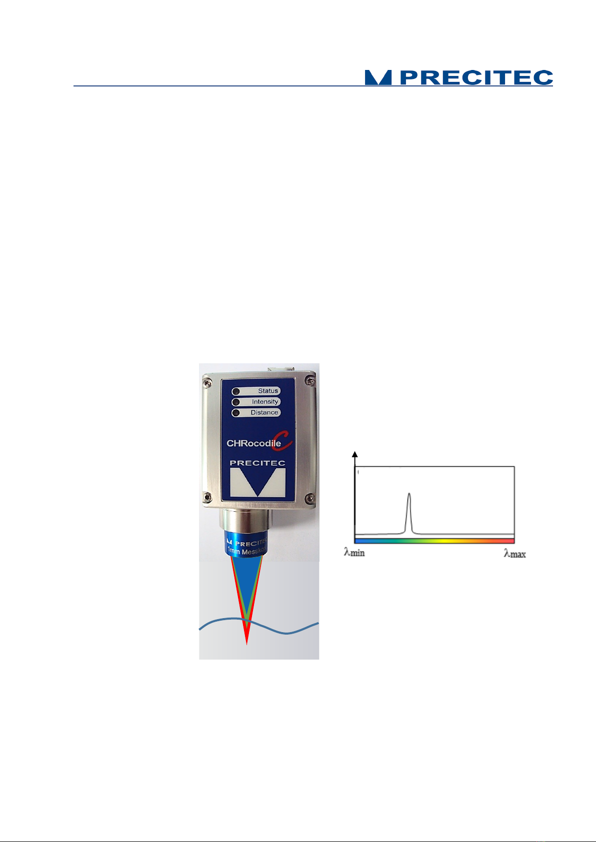
Application type 1
Chromatic distance measurement
Topographic, profile or roughness measurements are performed with
distance data measurement. With single-point sensors, i.e. CHRocodile
C, one spot is focused on the surface of the measured object using an
optic with a known chromatic aberration. The reflected light is more
intense for the wavelength in focus on the surface. Reflected light is
spectrally analyzed and the spectral response is a peak centered on
focused wavelengths. The spectral peak positions determine the distance
to the surface information. The distance is calculated and transmitted to
host computer at up to 4KHz frequency See Fig. 2-3.
Fig. 2-3: Chromatic measurement principle, distance measurement
Intensity
Chromatic
optical probe
Spectral signal
Target

15
Application type 2
Chromatic thickness measurement
Thickness measurements can be performed when thickness data is
selected. If a transparent material is within the measurement volume of
the chromatic optical probe, the white light spot is focused on both the
two surfaces of the measured object. The reflected light is more intense
for the two wavelengths in focus on the two surfaces. Reflected light is
spectrally analyzed and the spectral response is constituted of two peaks
centered on focused wavelengths. Considering the refractive index of the
object, one can determine the thickness of the object at the spot light
location. This thickness data is calculated and transmitted to host
computer at up to 4KHz frequency. See Fig. 2-4.
Fig. 2-4: Chromatic measurement principle, thickness measurement
Target
Chromatic
optical probe
Intensity
Spectral signal

16
2.5 Typical applications (Overview)
A broad range of possible applications is available to this highly precise sensor.
The CHRocodile C is the most compact sensor based on confocal chromatic imaging principle. This
sensor is perfectly suitable for demanding measuring tasks, like non-contact measurement of
microtopography, layer thickness measurements. It could be used both on various reflecting and
scattering surfaces.
The PRECITEC confocal chromatic compact sensor is very well adapted to industrial environment, as
no optical cable are connected to the CHRocodile C unit. The absence of optical cables, promotes
robustness and compactness of the measuring device, and also facilitates the integration and use on
a motorized moving system, such as a coordinate measuring machine (CMM). Then this new type of
sensor overcomes the industrial constraints induced by fiber optic cables that are known to deteriorate
when the measuring device is subject to high accelerations and / or rotational movements.
The CHRocodile C offers the ability to perform fast and accurate metrological control of production, by
being built on automatic or semi-automatic inspection machines, or by being directly integrated on
production line for 100% inspection of manufactured parts. In this, this new technology fully meets the
current needs of the industry as it is suitable for many applications:
- The measurement of wafer in the field of semiconductor and generally microelectronics,
- The measurement and online control of mechanical or optical parts,
- Or even the measurement and control of glass or plastic film thickness.
Other fields of applications exist, the common point is to seek a cost effective measurement system
going, more and more compact, as flexible as possible, and highly accurate. It is the case in laboratory
environment and even more in industrial environment. It appears clearly here that the CHRocodile C
unit of measurement meet these different needs.
Optical Head
Application
Probe
200µm
Probe
1mm
Probe
4mm
Probe
10mm
Electronics
Micro-Electronics
Mechanics
Micro-Mechanics
Optics
Micro-Optics
Shape
Flatness
Roughness
Plastic and glass thickness
Thin film thickness
Coating thickness
Table 2.1: Sensor applications
17
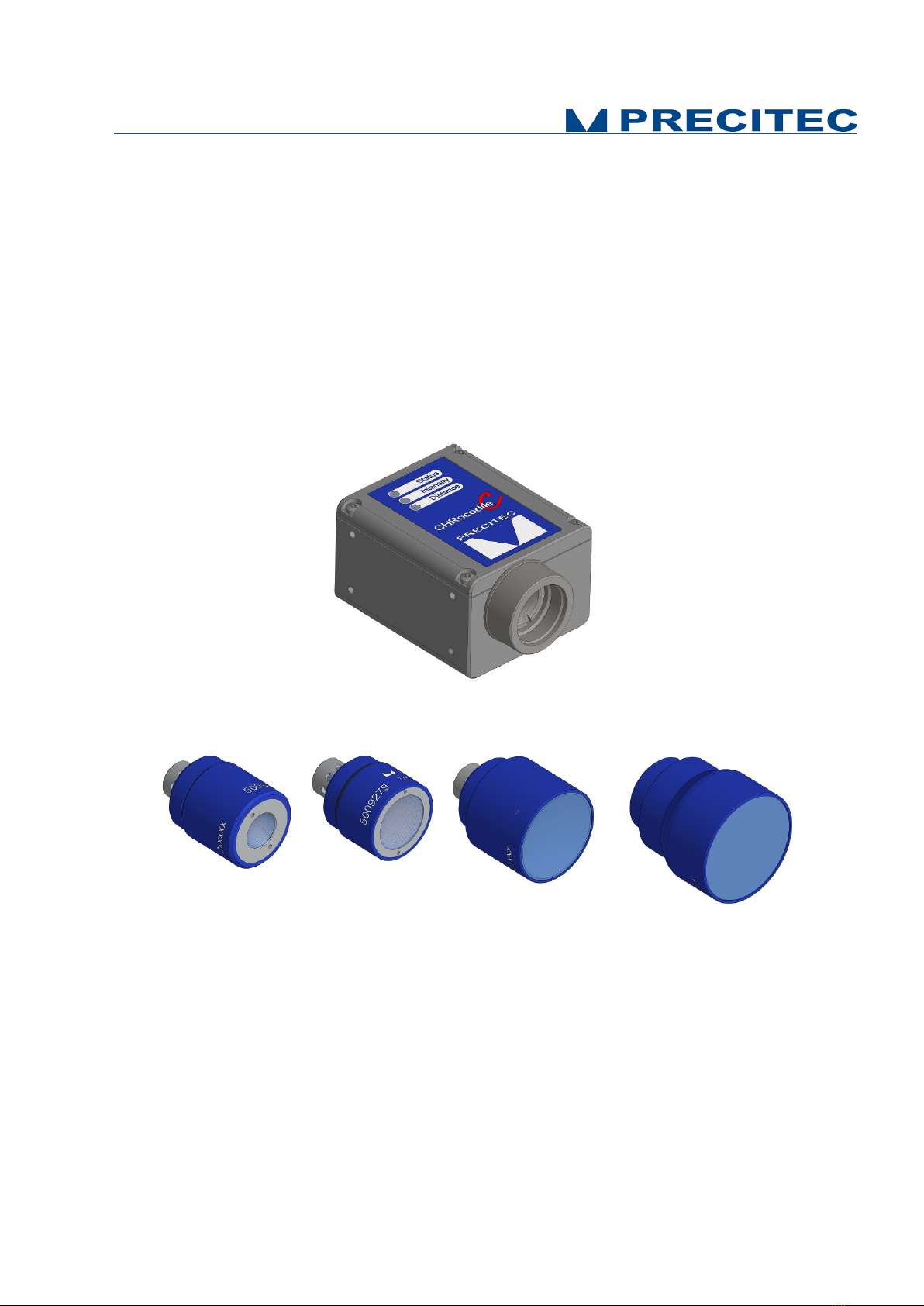
2.6 List of Deliverables
- One operational confocal chromatic unit (see Fig. 2-5),
- One operational optical probe (see Fig. 2-6),
- Power Supply Adapter (100-240VAC to 24VDC +/-10%),
- Ethernet cable,
- A CD with DLL and firmware,
- Software user guide,
- Operation Manual,
- Calibration report.
Fig 2-5: CHRocodile C unit 3D view:
Fig 2-6: Optical Head 3D view: a- 0.2mm b- 1mm c- 4mm d- 10mm
18
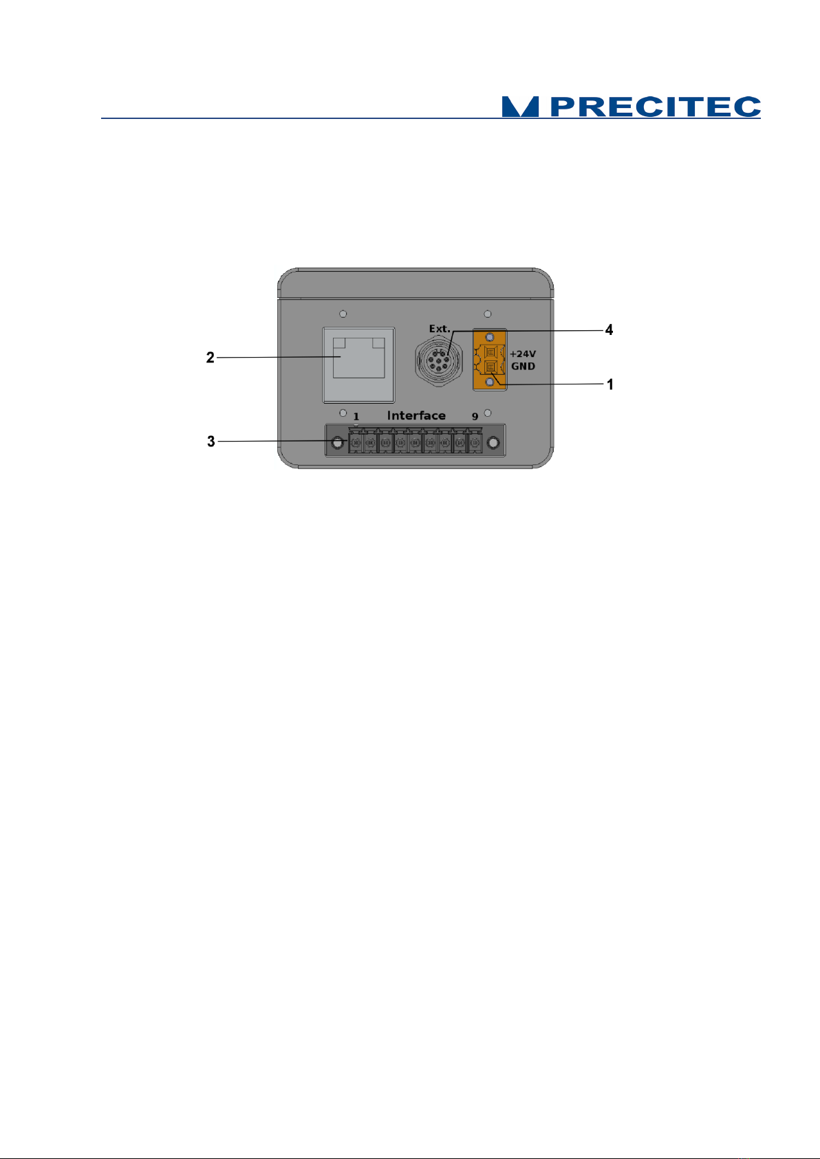
2.7 Connections and Interfaces
All of the connection ports for the sensor unit are located at the rear of the system (see Fig 2-7):
1. Power supply jack,
2. Ethernet interface, RJ45 port
3. 9-PINS Multipoint interface connector (Trigger / Serial communication)
4. 8-PINS round connector (analog converter module connection)
Fig. 2-7: CHRocodile C rear panel: Connections
2.7.1 Power supply jack
The CHRocodile C has two pluggable screw terminal for power supply with 24VDC +/-10%.
Connect the set of power cable supply associated to the Power Supply Adapter (100-240VAC to
24VDC +/-10%) delivered with the CHRocodile C unit.
2.7.2 Ethernet connector
The CHRocodile C has a RJ45 standard connector for Ethernet communication.
Connect the isolated RJ45 standard connector from the CHRocodile C unit to an Ethernet network
(PC). Ethernet supports the data transfer and can also be used for setting configuration by using $
command protocol (Cf. command SODX in Appendix 1), or for loading Calibration Table (Cf. command
TABL in Appendix 1). Ethernet communication allows to transmit a maximum of 16 data values at 4
KHz.
2.7.3 Trigger Input/Output and RS422 serial communication
The Trigger input/output use a multipoint connector interface (9 pins). This connector is used for
trigger Input / Output and for RS422 serial communication (Cf. Table 2-2 and Table 2-3).
The trigger options make the lighting cycle externally controllable and the synchronization between
e.g. a scanning system cycle and the CHRocodile C measurement rate. This means that external
triggering is possible for every measurement up to the full measurement rate of 4000Hz.

19
The interface contains the connection points for the synchronization and RS422 or RS232 serial
communication.
The serial RS232/RS422 is interfaced on the multipoint connector interface (9 pins). Serial
communication are mostly used for sending command as a hyper-terminal, and can also support data
transfer. The maximum transfer rate RS232/RS422 is 1843200 Bd.
PIN
SIGNAL
1
RS232 TX / RS422 TX-
2
RS232 RTS / RS422 TX+
3
RS232 CTS / RS422 RX-
4
RS232 RX / RS422 RX+
5
GND
6
Sync In
7
Sync Out
8
Reserve
9
GND
Table 2.2: Multipoint connector PIN / Signal correspondence
Signal
Function
Description
RS422
RS422
Interface
RS422 (differential signaling) Interface, internally terminated,
no handshaking
RS232
RS232
interface
RS232 interface, RTS/CTS handshaking possible
Sync In
Sync. Input
Positive slope from 0V to 5-24V causes according to the
settings of the sensor:
starts the continuous measurement, if the command
wait for trigger was received first (TRG Command)
starts the single measurement in mode trigger each
(TRE Command)
When in TRW mode, a positive slope starts continuous
measuring, a negative slope stops the measurement
the input has an internal 10 kΩ pullup-resistor to 5 V.
Sync Out
Sync. Output
Sync Output
Positive slope 0 V to 5 V with the start of each measurement.
Table 2.3: Interface

20
Remark: As the Sync-input has a weak pull-up to 5V, your trigger source definitely needs to be able to
sink that current in order to pull the input down to Gnd. So as a trigger source, you can use an open
collector transistor output, that pulls to ground or a push pull output. The input can support 24V, but
the trigger threshold is always at approximately 2V. The trigger occurs on the rising edge, that means
when the external pulldown transistor releases the input or when the pushpull drives to 5V.
Wait for trigger –signal characteristics to Analog Out
The sensor stops after the current data telegram is transmitted and
goes into a standby mode.
The last transmitted analog value persists until the next exposure
(also see TRG command).
2.7.4 External analogue converter box connection
The 8 pins round connector is used for external analogue converter box connection. This option can
be added to the CHRocodile C in order to obtain an analogue output. Also it is possible to add up to 2
encoder-input using this external analogue converter box connection.
The incremental encoder-input makes it possible to precisely assign the measurement point and axis
position without additional hardware. The CHRocodile C can manage with 2-axis encoders if the
optional analogue converter box is connected to the CHRocodile C 8-pins mini-DIN connector.
For an exact distance measurement it is necessary for every measurement value to be assigned to the
exactly correct spatial coordinates. This data must be recorded in the system and transferred to the
evaluation processing unit over the internal interface. To accomplish this, the sensor must be
equipped with the analogue box accessory.
Table of contents


