Preco S Series Quick start guide

1
FLIGHT CONVEYOR
S, SL and SB series
ASSEMBLY AND OPERATIONAL
MANUAL

2
Content
INTRODUCTION.................................................................................................................................................................... 4
EU DECLARATION OF CONFORMITY............................................................................................................................ 5
SAFETY INSTRUCTION........................................................................................................................................................ 6
General safety.................................................................................................................................................................... 6
Electrical safety ................................................................................................................................................................. 7
Security stickers................................................................................................................................................................ 7
STANDARD EQUIPMENT ................................................................................................................................................... 8
Standard equipment for S type.................................................................................................................................. 8
Standard equipment for SL type................................................................................................................................ 9
Standard equipment for SB type .............................................................................................................................10
CONVEYOR SUPPORT.......................................................................................................................................................11
LIFTING CONDITIONS.......................................................................................................................................................12
ASSEMBLY OF FLIGHT CONVEYOR..............................................................................................................................13
Tension unit .....................................................................................................................................................................14
Drive unit...........................................................................................................................................................................14
Overflow membrane.....................................................................................................................................................15
Top cover dismantling .................................................................................................................................................15
Tension unit, extensions and drive unit.................................................................................................................16
Chain assembly...............................................................................................................................................................17
Chain tension...................................................................................................................................................................18
Top cover assembly ......................................................................................................................................................18
Double-sided inlet assembly.....................................................................................................................................19
Inlet assembling .............................................................................................................................................................20
Outlet assembling..........................................................................................................................................................20
ACCESSORIES.......................................................................................................................................................................21
Cover of inner-floor ......................................................................................................................................................22
Enclosed double-sided inlet ......................................................................................................................................23
Slide assembly.................................................................................................................................................................24
Motor cover assembly..................................................................................................................................................25
Slide cover assembly ....................................................................................................................................................25
Support truss...................................................................................................................................................................26
Shaft speed monitor.....................................................................................................................................................27

3
ELECTRICAL ASSEMBLY....................................................................................................................................................27
STARTING UP THE FLIGHT CONVEYOR .....................................................................................................................28
MAINTENANCE....................................................................................................................................................................28
TROUBLESHOOTING .........................................................................................................................................................29
MAINTENANCE PERIODIC TABLE.................................................................................................................................30

4
INTRODUCTION
The assembly and operating manual contains information about flight conveyor technical
specifications, main parts, accessories, assembly, general and electrical safety instructions.
Preco flight conveyors are ideal for product transportation horizontally or at an angle up to
45 degrees. Available in various models and sizes, depending on required capacity. Preco conveyors
are made in an industrial performance that guarantees safety in operation.
Conveyor is designed for indoor and outdoor use in temperatures from -25℃to + 40℃.
The conveyor must be connected to a three-phase AC power source with a current frequency
of 50Hz, 380V voltage, grounding and safety switch.
IMPORTANT!
•Read this assembly manual carefully before starting the installation and start-up
operations
•Electrical installation work may be carried out only by a qualified electrician / electro
engineer
•Always disconnect conveyor from the power source before installation, maintenance
and repair of the conveyor
•Keep the manual in an accessible place.
CE label:
The label is located on the tension section and is proof that the machine is manufactured in
accordance with EU directives and safety regulations.
A –Manufacturer
B –CE marking
C –Conveyor type / model
D –Conveyor serial nr.
E –Year of production
B
A
C
D
E

5
EU DECLARATION OF CONFORMITY
Manufacturer: Ltd. “PRECO”
Address: Dravnieku Street 16, Lielvārde, Lielvārdes reg.,
LV-5070, Latvia
Tel.: +371 650 71 850
We declare that
Equipment: Flight conveyors
Equipment models: S40, S80, S100, S150, S200, S300, S500 /
S40B, S80B, S100B, S150B, S200B, S300B, S500B /
S40L, S80L, S100L, S150L, S200L, S300L, S500L
Year of production:
Are designed and manufactured in accordance to following directives and standard regulations:
•MK Nr.195 - 2008.03.25. (2006/42/EU) Machinery Directive
TP TC 010/2011 Technical Regulation of the Customs Union
•MK Nr.209 - 2016.04.12. (2014/35/EU) The Low Voltage Directive
TP TC 004/2011 and TP TC 020/2011 Technical Regulation of the Customs Union
•ATEX 2014/34/EU Zone 21, category II 2D/0D Safety of machinery. Equipment and
protective systems intended for use in potentially explosive atmospheres.
•LVS EN ISO 12100:2010 Safety of machinery. General principles for design - Risk
assessment and risk reduction
•LVS EN ISO 13857:2008 Safety of machinery. Safety distances to prevent hazard zones
being reached by upper and lower limbs.

6
SAFETY INSTRUCTION
General safety
The manual must be freely available to assembly personnel, electricians, service engineers and
equipment operators at any time. Incorrect assembly and/or operation may lead to personal injury
or damage to the equipment. It can also cause malfunctions or a reduction in capacity. Carefully read
the assembly and operational manual before assembly, electrical equipment connection,
maintenance or operation start. If any part of these instructions is not understandable, please contact
with manufacturer for assistance.
WARNING!
•Disregarding warnings given in this instruction may cause serious personal injury or death.
•Ignoring the instructions given may cause damage to the equipment.
•Ensure that everyone responsible for assembly, electrical connection, maintenance and
operation of the conveyor has read and understood the instructions and safety information.
•Wear protective gloves, head protection, steel-toed boots, ear protection, protective goggles
and high visibility vest when carrying out assembly, electrical connection, maintenance and
operation of conveyor.
IMPORTANT!
•For drive and tension section maintenance whose supports are located at the height of
more than 2 m from the floor it is required to assemble service platforms with handrails.
The service platforms must comply with local government laws and regulations.
•Conveyor supports are not included in standard delivery. It is customer responsibility
to arrange supports for the conveyor. Maximum distance between them must not
exceed 6 m.
•All rotating parts must be safely secured and protected. Do not operate with safety
guards removed.

7
Electrical safety
WARNING!
•Stop the conveyor and turn off electric power before attempting any type of assembly,
electrical or maintenance work
•Do not start the conveyor with removed or damaged safety covers.
•All electrical connections must be mounted properly and fully enclosed. Electrical installation
must be performed by Qualified electrician.
•Conveyor usage is forbidden without electrical grounding.
INFORMATION!
•If the conveyor is assembled outdoors, it must be fitted with a motor cover.
•If a short circuit occurs, ensure that the electrical equipment is in working order before
continuing an operation.
•Ensure that the electrical equipment is kept free from dirt, dust, moisture and electrostatic
charge.
Safety stickers
1.
Read instruction carefully before
use!
2.
High voltage! Electric shock risk
3.
Warning for rotating drum
4.
Warning for rotating drive shaft
5.
Electrical grounding (on the side
of the conveyor)

8
STANDARD EQUIPMENT
Flight conveyor is manufactured from galvanized sheet metal (275 g/m2) in accordance with
the EU Machinery Directive 2006/42/EC, EU Low Voltage Directive 2006/95/EC and designed in
accordance with EN ISO 12100 part 1-2 which guarantees machinery safety. Intended for horizontal
or elevated transportation up to 45° angle. Model capacity for grain with 750 kg/m3density and 15%
moisture content. Transporting beans or peas conveyor capacity needs to be reduced by half using
a slide or a flow regulator. Please take note that every 1% increase in moisture content above 15 %
decreases capacity by 3-4 %.
Standard equipment for S type
Model
S40
S80
S100
S150
S200
S300
S500
Capacity, t/h
25
60
80
120
150
250
500
30
80
100
150
200
300
50
60
Capacity, m³/h
33-91
58-124
110-159
174-226
238-303
343-440
584-723
Chain speed, m/s
0.31-
0.92
0.47-
0.93
0.64-
0.79
0.62-
0.94
0.66-
0.88
0.71-
0.86
0.57-
0.76
Chain type, FV
63-63
90-100
90-100
112-125
140-160
180-160
250-160
180-160
250-160
315-160
315-160
400-160
400-160
Thickness, mm
side/floor
2/2
2/2
2/2
3/3
3/3
4/5
4/5
*On-demand performance of other models ** Capacity for wheat 0.75 t/m3, 15% moisture
1. Drive unit
2. Tension unit
3. Extensions in various standard lengths
4. Inlet in respective angle
5. Outlet in respective angle

9
Standard equipment for SL type
Model
S40L
S80L
S100L
S150L
S200L
S300L
S500L
Capacity, t/h
25
60
80
120
150
250
500
30
80
100
150
200
300
50
60
Capacity, m³/h
27-84
54-112
110-139
158-202
202-267
294-440
528-667
Chain speed, m/s
0.28-
0.83
0.44-
0.86
0.60-
0.75
0.70-
0.87
0.61-
0.81
0.62-
0.81
0.57-
0.70
Chain type, FV
63-63
90-100
90-100
112-125
140-160
180-160
250-160
180-160
250-160
315-160
315-160
400-160
400-160
Thickness, mm
side/floor
2/2
2/2
2/2
3/3
3/3
4/5
4/5
*On-demand performance of other models ** Capacity for wheat 0.75 t/m3, 15% moisture
1. Drive unit
2. Tension unit
3. Extensions in various standard lengths
4. Outlet in respective angle
5. Bend section in respective angle

10
Standard equipment for SB type
Model
S40B
S80B
S100B
S150B
S200B
S300B
S500B
Capacity, t/h
25
60
80
120
150
250
500
30
80
100
150
200
300
50
60
Capacity, m³/h
28-84
54-112
110-139
158-202
202-267
294-440
528-667
Chain speed, m/s
0.28-
0.83
0.44-
0.86
0.60-
0.75
0.70-
0.87
0.61-
0.81
0.62-
0.81
0.57-
0.70
Chain type, FV
63-63
90-100
90-100
112-125
140-160
180-160
250-160
180-160
250-160
315-160
315-160
400-160
400-160
Thickness, mm
side/floor
2/2
2/2
2/2
3/3
3/3
4/5
4/5
*On-demand performance of other models ** Capacity for wheat 0.75 t/m3, 15% moisture
1. Drive unit
2. Tension unit
3. Double-sided inlet
4. Outlet in respective angle
5. Bend section in respective angle
6. Extensions in various standard lengths

11
CONVEYOR SUPPORT
Flight conveyor must be placed on a stable and even surface. We recommend to use support
feet. The maximum free span distance in the picture below. Conveyor support feet are not included
in standard delivery.
WARNING!
The conveyor must be level widthwise and centered lengthwise.
12
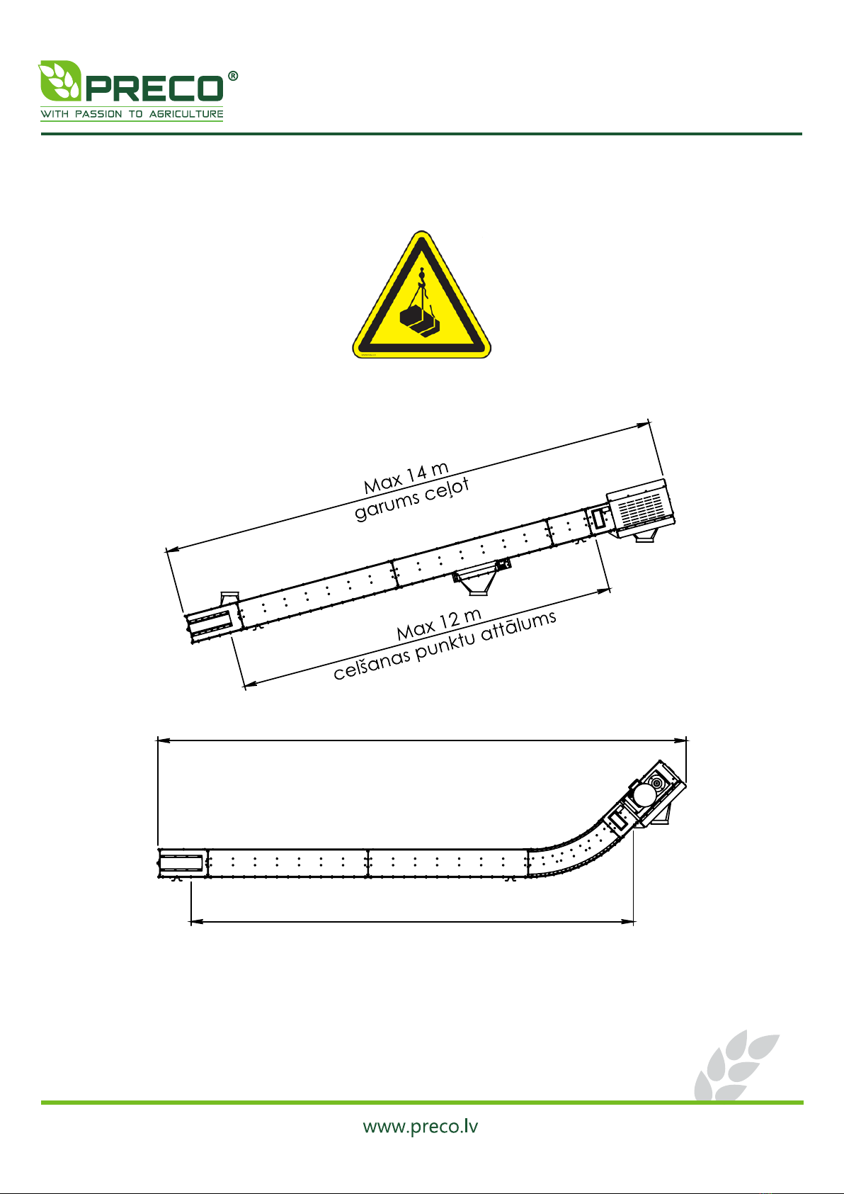
LIFTING CONDITIONS
Lifting equipment must meet technical requirements and it shall be able to lift conveyor and
its parts.
Attention! Lifted load! Always make sure that no one is standing under lifted load.

13
ASSEMBLY OF FLIGHT CONVEYOR
Please check that there is enough space for conveyor assembly. The conveyor can be
assembled directly in the place or assembled separately and then lifted in the place. Find out location
of inlet and outlet before starting the assembly. Conveyor consists of tension section, intermediate
sections, bend section, drive section, chain, overloading membrane, inlet and outlet. Manufacturer
provides various type of inlets and outlets, weather cover for motor, reversible drive unit, shaft speed
monitor with cover, inline and lateral outlet slides
INFROMATION!
Bolt tightening must be done according to maintenance instructions.
Bolt torque table (Nm)
Bolt size
Bolt strength grade
8.8
10.9
12.9
M4
3.2
5
6
M5
6.4
9
11
M6
11
16
19
M8
27
39
46
M10
53
78
91
M12
92
135
155
M16
230
335
390
M20
460
660
770
M24
790
1150
1300
M30
1600
2250
2650
M36
2780
3910
4710
M42
4470
6290
7540

14
Tension unit
Delivered assembled and fitted with threaded rods (1) for chain tensioning.
Drive unit
Drive unit is complete with gearbox motor (1) and fitted with overloading membrane (2).
For motor maintenance and overloading membrane manual, please see the attached supplier
information.

15
Overflow membrane
MOLLET MFE-EE is assembled by manufacturer. For overflow membrane regulation, please
see the attached supplier manual.
Top cover dismantling
Before you start to assemble tension unit, extensions and drive unit, you have to dismantle
top covers (1) and connection plates (2), please see picture below. Dismantled bolts and nuts you
will need when top covers will be assembled back to conveyor.

16
Tension unit, extensions and drive unit
Standard drive unit is equipped with a pair of inspection windows. Standard extension lengths
are 0.3 m, 0.6 m, 1.2 m and 2.4 m. Bend section is available in 15, 30 or 45 degrees. By combining
multiple extensions it’s possible to acquire the desired conveyor length.
Connect sections using connecting plates. Bolt them together with included bolts and nuts.
INFROMATION!
If you have a conveyor with more than one extension, connect it first and assemble drive
section in the end.

17
Chain assembly
Pull the chain into the conveyor. Shorten if necessary. Connect the chain with chain
connections, as it is shown in the picture below. Arrow shows chain direction. Assemble chain and
tighten it with tighten bolts on the tension section.

18
Chain tension
Check the chain tension by pressing it down between the two chain return pulleys. It is
tensioned correctly if it can be pressed down to 3-5 mm and max 30 mm on the tension pulley, as
it is shown in the picture. Adjust the chain tension on regular basis.
Top cover assembly
When assembling top covers use hermetic sealant between mating surfaces.

19
Double-sided inlet assembly
Dismantle connection plates from extensions. Assemble extensions with double-sided inlet.
Bolt them together with included bolts and nuts. Mount covers and connection plates.
Remove all screws from the end of the double-sided inlet. Connect two inlets using the
removed screws as shown in the image below.

20
Inlet assembling
Attach inlet flange to the extension’s cover,
cut the hole for inlet and drill the holes for bolt
assembling (inlet flange should be used as stencils),
as it is shown in the picture below. Minimum
distance is 1000 mm from the end of tension unit.
Then mount the inlet flange using included bolts
and nuts. Use hermetic sealant supplied for sealing.
Outlet assembling
Mount outlet flange to drive
unit using bolts and nuts, as shown
in the picture.
Other manuals for S Series
1
This manual suits for next models
23
Table of contents
Other Preco Accessories manuals


Popular Accessories manuals by other brands


Leviton
Leviton Provolt ODC05-UDW installation instructions

Panasonic
Panasonic AG-BS300E operating instructions

Huawei
Huawei Airbridge cBTS3612 Maintenance manual

Ashcroft
Ashcroft GC35 Installation and Maintenance

HoMedics
HoMedics Aroma ARMH-590 instruction manual

FARMDROID
FARMDROID FD Base Station V2.0 Original user manual


