PREFORMED LINE PRODUCTS POWER RAIL P8 User manual

Assembly InstructIons
step-by-step
assembly and installation
Assembly InstructIons
Version 2, Rev A
SP3412-1 PCN 021317-1
POWER RAILTM P8

Assembly Instructions, Power Rail P8 (Version 2, Rev A) 1
The Power Rail P8 conforms to ANSI/UL
UL2703 (2015) Standard for Safety First
Edition: Mounting Systems, Mounting Devic-
es, Clamping/Retention Devices, and Ground
Lugs for Use with Flat-Plate Photovoltaic
Modules and Panels.
Electrical
Note: Electrical installations must be in
accordance with the National Electric
Code ANSI / NFPA 70. Contact your
local Authorities Having Jurisdiction
(AHJ) for additional details.
Max Overcurrent Protective Device (OCPD)
Rating: 25A
Equipment Grounding Conductor Sizing
Module Fuse
Rating Copper Wire Size
<15 AMPS #14 AWG 90°C
<20 AMPS #12 AWG 90°C
20-60 AMPS #10 AWG 90°C
Splice Plates
Slice Plates have been tested per UL2703
Bonding & Grounding requirements without
the use of Bonding Jumpers.
See assembly procedures for proper
assembly.
Module Clamps
Module clamps have integrated grounding
and have been tested to UL 2703
See Module Compatibility List for list of
approved modules.
Module Orientation: Portrait or Landscape
Power Rail
TM P8 Ratings
Fire Class Resistance Rating
The system re class rating is only valid when
the installation is conducted in accordance with
this manual.
Meets the requirements of Class A Steep Slope
Flush-Mounting Applications when using Type 1,
Listed Photovoltaic Modules.
Testing conducted with a 5” Gap (distance be-
tween roof covering and PV module frame) per
UL1703 allows the system to be installed with
any gap per manufacturer’s instructions.
Steep Slope refers to roofs with slopes greater
than or equal to 2:12.
Structural Certication
Mechanical Load Rating: Meets the minimum
design load rating of UL2703 section 21.4
(10 psf downward, 5 psf upward, and 5 psf
downslope) load. Actual system structural ca-
pacity dened by PE review.
Marking
Product markings identied per UL2703 are to
be located in a location that is readily accessible
for inspection.

2 Assembly Instructions, Power Rail P8 (Version 2, Rev A)
About the product
The Power Rail top-clamping PV module
mounting system is engineered to reduce in-
stallation costs and provide maximum strength
for parallel-to-roof or tilt up mounting applica-
tions.
Designed with the professional PV solar in-
staller in mind, the top-clamping rails utilize a
single tool with a revolutionary RAD™ Fasten-
er for faster bolt placement. The unique shape
of the RAD provides an anti-rotation feature,
locking the bolt in the proper orientation when
installed. The high strength rigid rails also in-
clude an integral wiring channel for securing
cables and providing a professional nish.
The Power Rail Mounting System features
the industry’s broadest selection of mounting
supports, designed for secure and water tight
attachments to any roof style.
For recommendations on a specic installa-
tion, please:
Visit www.DPWSolar.com and select the Pow-
er Rail Conguration Design Tool.
Contact us by Phone: 800-260-3792
Send an Email request: info@DPWSolar.com
About these instructions:
• They do not include any information on the
selection or installation of attaching hard-
ware to be mounted to the roof substrate.
For information on compatible attaching
hardware, see our publication titled “Pow-
er Rail Design Guidelines”.
• They begin after all roof mounted attach-
ing hardware has been installed and se-
cured to the roof substrate.
• They show the Power Rail Mounting Sys-
tem being installed on the “Power Rail PV
Flash” roof attachment system.
Power Rail P8
WARNING
Follow the pro-
cedures and
precautions in
these instructions
carefully.
• These instructions are intended to be used
by individuals with sufcient technical skills
for the task. Knowledge and use of hand
tools, measuring devices and torque values
is also required.
• These instructions include various precau-
tions in the forms of Notes, Cautions, and
Warnings. These are to assist in the as-
sembly process and/or to draw attention to
the fact that certain assembly steps may be
dangerous and could cause serious personal
injury and/or damage to components. Follow-
ing the step-by-step procedures and these
precautions should minimize the risk of any
personal injury or damage to components
while making the installation not only safe but
an efcient process.
Periodic Inspection
Periodic re-inspection is a recommended system
maintenance procedure to check for any loose
components and any corrosion. If any loose com-
ponents and any corrosion is found, the affected
components are required to be replaced immedi-
ately, with the original mounting system manufac-
turer’s component parts.
Required Tools
o1/2 inch wrench or socket for 5/16 inch
module clamp hardware
oTorque wrench
oRatchet wrench
oRatchet extension bar
oTape Measure
oSquare
Assembly Instructions, Power Rail P8 (Version 2, Rev A) 3
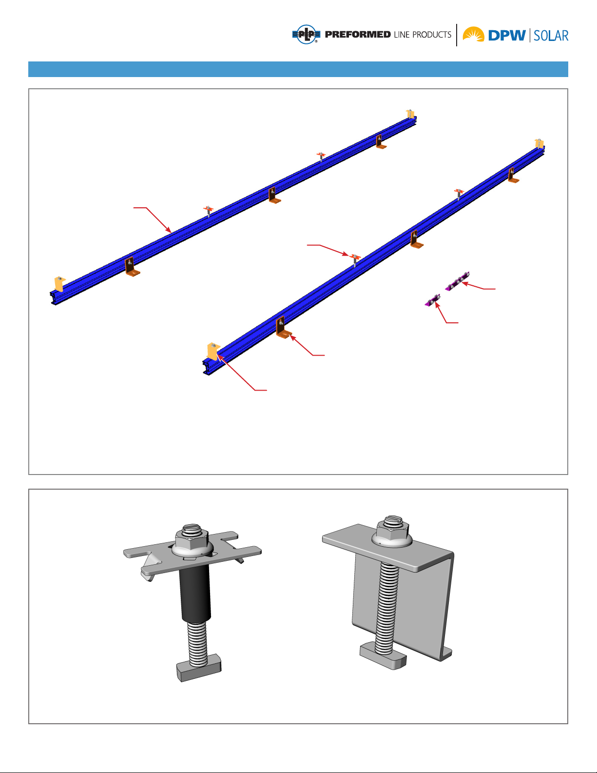
Power Rail P8 Main Components
There are ve main components and attaching hardware.
RAD End
Clamp
“L” Foot
AMPTM Clamp
Bonding Clamp
P8 Power Rail
Splice Plate
(two hole)
Splice Plate
(four hole)
Factory Assembled
AMP Clamp
Bonding Clamp
Factory Assembled
(patented) RAD
End Clamp
4 Assembly Instructions, Power Rail P8 (Version 2, Rev A)
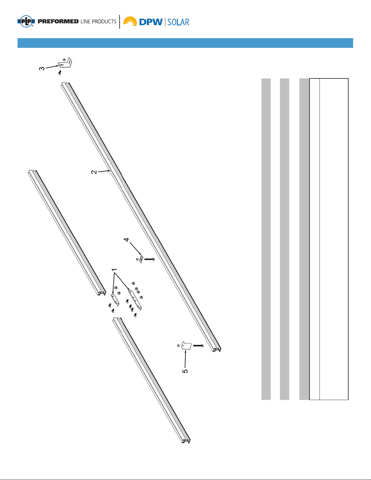
Power Rail P8 Parts Identication
Item Description Qty
1Splice Plate, two or four hole, (5/16” x 3/4”) turn bolts, ange nuts 1 per Rail Joint
2 Power Rail P8 2 per Rail Set
3“L” Foot, (5/16” x 3/4”) turn bolt, ange nut Refer to Power Rail Design Guidelines
4AMP Clamp, (5/16” x *) RAD bolt, ange nut 2 per 3/8” gap between modules
5RAD End Clamp, (5/16” x *) RAD bolt, ange nut 4 per Rail Set
* 2”, 2-1/4”, 2-1/2”, or 2-3/4” bolt. Length is dependent on depth of PV Module frame
Notes:
1. Install Mid Clamp with AMP Clamp RAD bonding Mid Clamp.
2. Option to install Universal End Clamp, End Clamp with carriage bolt or RAD End Clamp.
Assembly Instructions, Power Rail P8 (Version 2, Rev A) 5
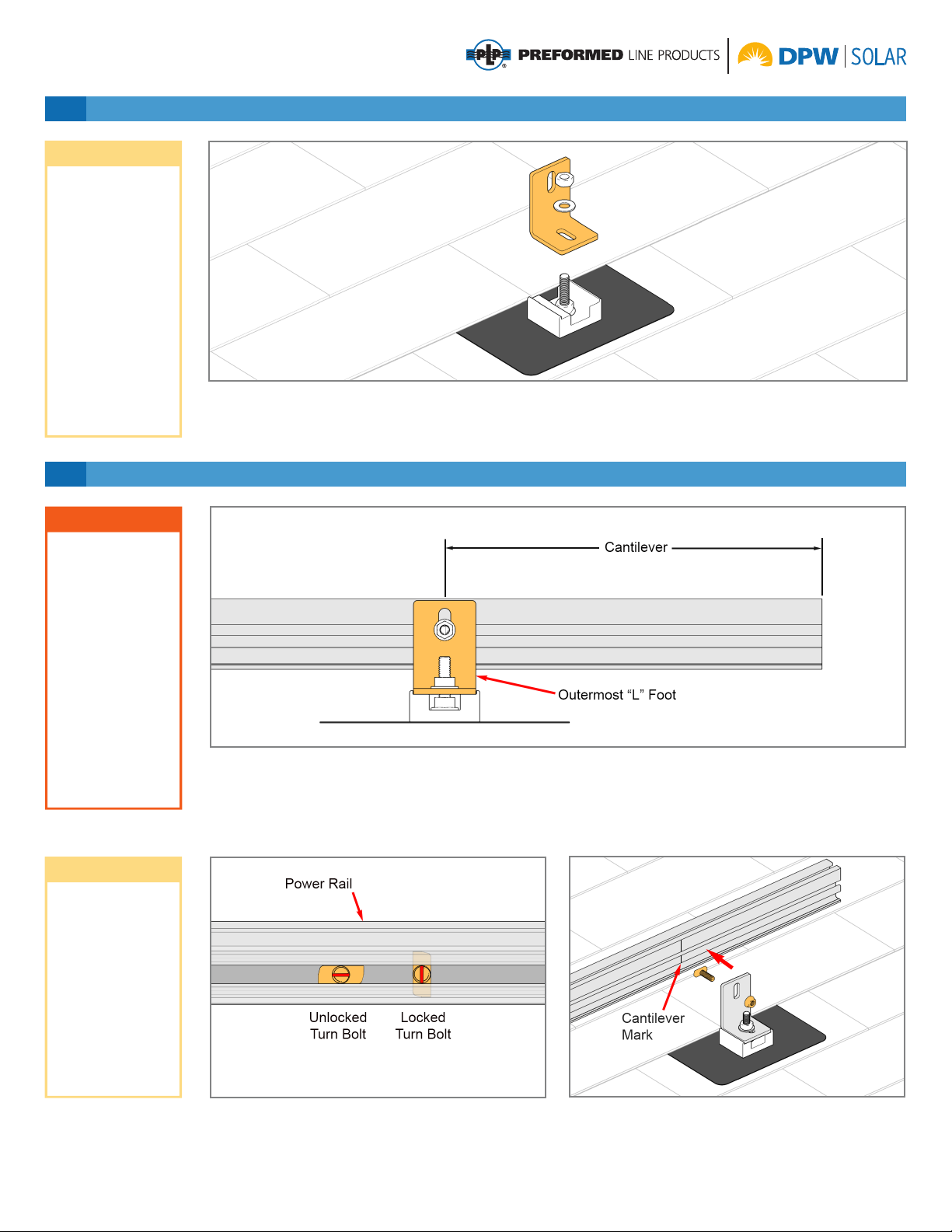
2 Attach Power Rail to “L” Feet
The Power Rail overhangs beyond the outermost
“L” Foot. This overhang is referred to as “cantilever”,
or abbreviated as “C’ver”. The distance between
adjacent “L” Feet is referred to as “span”. The length
of both the cantilever and the span are dependent on
1 Install the “L” Feet
Secure “L” foot to appropriate anchoring device per
the manufacturers instructions. Above is shown using
the Power Rail PV Flash and attaching hardware.
Position “L” foot on compression block and secure
with 5/16” Hex Nut and Flat Washer. Torque to 14-16
ft.-lbs.
CAUTION
NOTE
NOTE
Cantilever and
span dimensions
are a design spec-
ication. Consult
the design manual
to match these
dimensions to site
conditions. It’s im-
portant to use the
unique cantilever
and span dimen-
sion specic to the
install. Failure to do
so could lead to ex-
cessive deection
and/or premature
system failure.
L feet can be
attached directly to
the roof substrate
with the proper
hardware. See
Power Rail Design
Guidelines for more
information.
Information on
appropriate
anchoring
hardware is
available on an
individual product
basis.
several factors, unique to each installation and are
determined by the system design.
Measure and mark the cantilever dimension supplied
by the design manual onto the Power Rail.
Insert 5/16” x 3/4” Turn Bolt into Power Rail and
rotate 90-degrees, locking Turn Bolt in place. On the
outermost “L” Feet align center of the “L” Foot with the
cantilever mark on the Power Rail. Secure Power Rail
to “L” Foot with 5/16” Flange Nut. Torque to 14-16
ft.-lbs.
Turn bolts must
be locked into
the channel by
rotating clockwise
90-degrees. Use
the indicator slot on
the threaded end
to identify whether
or not the bolt has
been locked.
6 Assembly Instructions, Power Rail P8 (Version 2, Rev A)
CAUTION
This is a two per-
son activity.
In addition to the
difculties associat-
ed with working on
a sloped rooftop,
PV Modules are
heavy. One person
should hold and
align the modules
while a second per-
son secures mod-
ules with clamping
hardware. Failure
to do so could lead
to serious personal
injury and/or dam-
aged components.
4 Install the Modules
Splice Plates come in two congurations, 2-hole or
4-hole (above is a 4-hole). Insert 5/16” x 3/4” Turn
Bolts into Power Rail and rotate 90-degrees to lock
Turn Bolts in place. Align Splice Plate with center of
splice and secure to Power Rail with 5/16” Flange
Nuts. Torque to 14-16 ft.-lbs.
3 Splicing Power Rail with Splice Plates
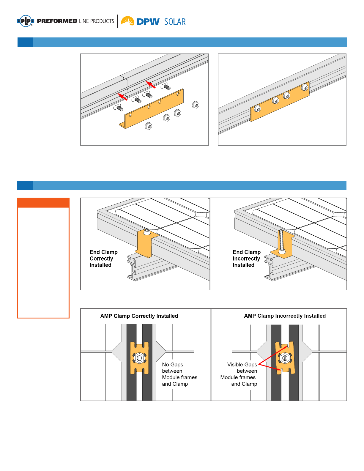
End Clamps must be installed as shown above left, not upside down as shown to the right.
AMP Clamp bonding Mid Clamps must be installed as shown at above left and not as shown to the right. There
cannot be any visible gaps between the bonding Mid Clamps and module frames.

Assembly Instructions, Power Rail P8 (Version 2, Rev A) 7
RAD End Clamps are used on the outer Modules.
Insert the 5/16” RAD Bolt into Power Rail and rotate
90-degrees clockwise to lock the RAD Bolt within the
Power Rail. Secure with 5/16” Flange Nut. Torque to
14-16 ft.-lbs.
AMP Clamp bonding Mid Clamps are inserted into the
Power Rail and positioned between adjacent Modules.
Insert the 5/16” RAD Bolt into Power Rail and rotate
4 Install the Modules (cont.)
90-degrees clockwise to lock the RAD Bolt within the
Power Rail. Push Modules against AMP Clamp. Tight-
en 5/16” Flange Nut. Torque to 14-16 ft.-lbs.
NOTE
The RAD bolts
used in the AMP-
Clamps and End
Clamps must
be locked into
the channel by
rotating clockwise
90-degrees. Use
the indicator slot on
the threaded end
to identify whether
or not the bolt has
been locked.

8 Assembly Instructions, Power Rail P8 (Version 2, Rev A)
Grounding/Bonding Path

Assembly Instructions, Power Rail P8 (Version 2, Rev A) 9
Compatible Modules - these modules meet the UL2703 standard
Manufacturer Frame
Thickness Model
Canadian Solar 40 mm CS6P‐250P, CS6P‐255P, CS6P‐260P, CS6P‐260P‐SD, CS6P‐265P, CS6P‐265P‐SD, CS6P‐270P
Heliene 40 mm 60P‐MIM
Kyocera 46 mm KU250‐6BCA,KU255‐6BCA, KU260‐6BCA, KU265‐6BCA
LG
35 mm LG300N1C‐G3, LG305N1C‐G3, LG310N1C‐G3
36 mm LG365N2W‐B3, LG375N2W‐B3
40 mm LG320N1C‐G4, LG325N1C‐G4, LG 335N1C‐G4, LG340N1C‐G4
46 mm LG375N2W‐G4
REC Solar
35 mm REC265TP, REC270TP, REC275TP, REC280TP, REC285
38 mm REC240PE, REC245PE, REC250PE, REC255PE, REC260PE, REC265PE, REC270PE
Silfab 38 mm SLA260M, SLA265M, SLA270M, SLA275M, SLA280M, SLA285M, SLA290M, SLA295M, SLA300M
Solar World
31 mm SW280 31mm
33 mm SW280, 285, 290, 295, 300 33 mm, SW 320 XL 33mm FR, SW 325 XL 33mm FR, SW 330 XL 33mm FR,
SW 335 XL 33mm FR, SW 340 XL 33mm FR, SW 345 XL 33mm FR, SW 350 XL 33mm FR
Suniva 38 mm OPT‐275‐60‐4‐100, OPT‐280‐60‐4‐100, OPT‐285‐60‐4‐100, OPT‐290‐60‐4‐100, OPT‐295‐60‐4‐100,
OPT‐300‐60‐4‐100
Sunpower 46 mm SPR‐327NE‐WHT‐D, SPR‐333NE‐WHT‐D, X21‐335‐BLK, X21‐345‐BLK
Suntech 50 mm STP270‐24/Vd, STP275‐24/Vd, STP280‐24/Vd, STP285‐24/Vd, STP290‐24/Vd, STP295‐24/Vd,
STP300‐24/Vd, STP305‐24/Vd
Topoint Solar 35 mm JTM185‐72M, JTM190‐72M, JTM195‐72M, JTM200‐72M
Trina 40 mm TSM‐290PD14, TSM‐295PD14, TSM‐300PD14, TSM‐305PD14, TSM‐310PD14, TSM‐315PD14,
TSM‐320PD14, TSM‐325PD14

Corporate Headquarters
660 Beta Drive
Mayfield Village, OH 44143
Telephone: 440.461.5200
Web Site: www.preformed.com
E-mail: [email protected]
Albuquerque Office
1700 Louisiana Blvd., Suite 130
Albuquerque, NM 87110
Telephone: 800.260.3792
Fax: 505.889.3548
Web Site: www.DPWSolar.com
E-mail: info@dpwsolar.com
© 2017 Preformed Line Products
PCN 021317-1 Version 2, Rev A
SP3412-1
Table of contents
Popular Inverter manuals by other brands


Solplanet
Solplanet ASW S Series user manual

Dometic
Dometic TEC29 EV AUS installation manual

Leroy-Somer
Leroy-Somer LSA 49.1 4P Installation and Maintenance

Mitsubishi Electric
Mitsubishi Electric 700 Series instruction manual

Endress
Endress ESE 2000I operating manual

Siemens
Siemens SINAMICS V20 Inverter Compact operating instructions


