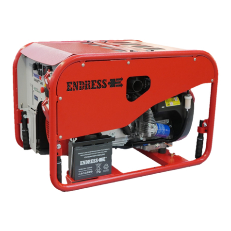
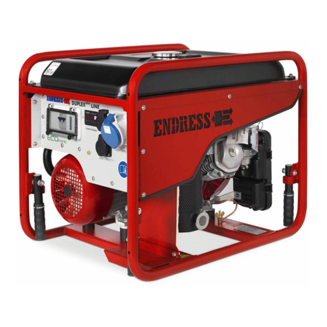
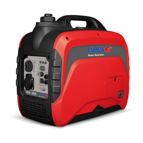
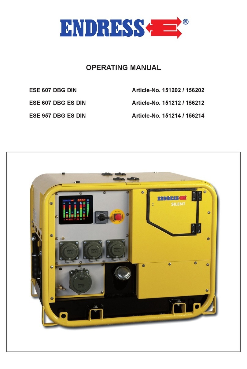
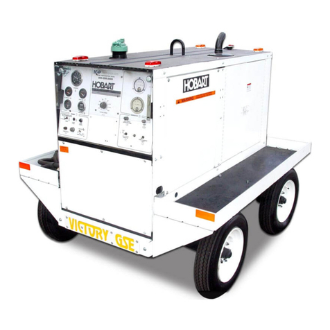
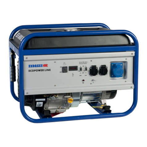
Endress ESE 2000I User manual

Operating Manual
Power Generators
ESE 2000I
Article No. 110 005
EN

Issuer ENDRESS Elektrogerätebau GmbH
Neckartenzlinger Straße 39
D-72658 Bempflingen, Germany
Email: info@endress-stromerzeuger.de
WWW: http://www.endress-stromerzeuger.de
Publication date March 2019
Copyright © 2014, ENDRESS Elektrogerätebau GmbH
This documentation, including all of its parts, is protected by copyright. Any
use or modification beyond the restrictions of the Copyright Act is forbidden
and subject to penalty without the consent of ENDRESS Elektrogerätebau
GmbH.
This applies in particular to copies, translations, microfilming, as well as
storage and processing in electronic systems.

3
Table of Contents
Overview / first steps ...............................................................................................................6
Intended use ............................................................................................................................6
Scope of delivery .......................................................................................................................6
Safety ........................................................................................................................................7
General safety warnings ...........................................................................................................7
Control elements......................................................................................................................9
Components of the electric generator .......................................................................................9
Components of the electric generator .....................................................................................10
Functioning and mode of operation.....................................................................................12
Operation ................................................................................................................................13
Transporting the generator ......................................................................................................13
Refuelling ................................................................................................................................15
Starting the generator............................................................................................................18
Connecting/disconnecting consumers................................................................................20
Charging batteries..................................................................................................................22
Deactivating the electric generator ......................................................................................24
Cleaning the electric generator.............................................................................................25
Storing/decommissioning the generator .............................................................................26
Maintenance ...........................................................................................................................27
Maintenance plan ....................................................................................................................27
Motor oil ..................................................................................................................................28
Air filter ....................................................................................................................................29
Cleaning the spark arrester .....................................................................................................32
Troubleshooting .....................................................................................................................33
Table of Contents

4
Technical specifications........................................................................................................34
Warranty conditions...............................................................................................................38
Environmental protection......................................................................................................40
List of illustrations
Figure 1: Scope of delivery................................................................................................................6
Figure 3: Labels on the generator ..................................................................................................... 9
Figure 4: Operating panel................................................................................................................10
Figure 5: Generator components..................................................................................................... 11
Figure 6: Refuelling ......................................................................................................................... 15
Figure 7: Filling in the oil.................................................................................................................16.
Figure 8: Wire rope hoist................................................................................................................. 19
Figure 9: Protective contact sockets................................................................................................20
Figure 10: Checking the motor oil....................................................................................................28
Figure 11: Air filter............................................................................................................................30
Figure 12: Spark plug...................................................................................................................... 30
Figure 13: Electrode gap................................................................................................................. 31
Figure 14: Cleaning the spark arrester............................................................................................ 32
Table of Contents
5
General note: The illustrations in these operating instructions do not always
comply completely with the actual design, in particular with
regard to the colour, and are to be considered a representation
of basic principles.
Table of Contents

6
Overview / first steps
Before operating the generator, read this manual thoroughly,
especially its safety instructions.
This manual instructs you on basic work with the generator and
helps you prevent hazards, repairs and defects.
Intended use
The generator is for producing 230V alternating current at
a frequency of 50 Hz and a nominal load of 1600 watts (for cos
phi = 1; also see p. 34).
Included in delivery
First inspect the delivery (see Fig. 1):
1. Generator
2. Tool kit
3. Oil filling funnel
4. 12V charging cable
Is the delivery complete?
Is there visible transport damage?
If so, always contact your dealer. If there is transport damage, do
not operate the device.
Figure 1: Included in delivery
Overview / first steps
Intended use

7
Safety
Safety
This section describes the basic safety regulations for operating
the generator.
DANGER!
High risk!
Failure to comply can cause injury or death.
CAUTION!
Moderate risk!
Failure to comply can cause property damage.
BEWARE!
Mild risk!
Instructions that must be observed when using the device.
General safety instructions
- Keep the operating manual at hand during operation.
- Always keep children and pets away from the power generator.
- Operate the device only on a level, non-skid surface. If
necessary, secure the device further.
- Keep at a minimum safety distance of one metre from
buildings or objects.
- It is forbidden to make technical changes.
- Repairs must be made only by a professional workshop.
(Safety-related components must be replaced only with
original replacement parts!)
- Do not operate the generator if it is visibly damaged.

8
DANGER! DANGER TO LIFE!
Shock hazard!
- Protect the device from dampness and moisture.
- Operation is only allowed when the device is dry. If the device
becomes damp or wet while running, stop it immediately.
- Operation with existing power supply networks is prohibited.
- Do not grasp the electrical plug with wet hands.
- Make sure that the power supply cable does not come into
contact with hot components of the generator and that the
insulation is not damaged in this way.
DANGER! DANGER TO LIFE!
Asphyxiation hazard!
- Operation in closed rooms is prohibited.
- Always make sure there is adequate ventilation.
FIRE / EXPLOSION HAZARD!
The generator becomes very hot during operation.
- It is forbidden to fuel the generator during operation or while it
is still hot.
- Keep away from direct sunlight. Beware of petrol odours
- Wipe up spilled fuel completely before you restart the device.
- Allow the device to cool after use.
- Always make sure there is adequate ventilation.
- Use safety gloves.
Safety

9
Operating elements
Operating elements
Components of the electric generator
1 6
2
3
4
5
Figure 3: Labels on the generator
No. Sign Name No. Sign Name
1Nameplate 4Caution: fire
hazard
2Read the operating
manual 5Caution: hot
surfaces
3Mind the noise level 6
Warning of
dangerous
electrical
voltage

10
Components of the electric generator
2
1
5
6
7
4 3
8
11
10
9
Figure 4: Control panel
1 Red LED oil warning 7 Protective contact socket, 230V/~
2 230V green LED (230V outlet has voltage) 8 Choke
3 Red overload LED (230V outlet, no voltage) 9 12V circuit breaker =
4 ECOtronic On/Off 10 12V = outlet
5 On/Off switch 11 Potential equalization (only for special
applications, specialist electrician required)
6 Fuel valve
Operating elements

11
Operating elements
1
2
3
4
5
6
Figure 5: Components of the power generator - 2
1 Recoil starter 4 Spark plug (behind side panel)
2 Tank cap with air-release valve 5 Air filter (behind side panel)
3 Exhaust 6 Oil filling (behind side panel)

12
Function and mode of operation
The power generator makes use of inverter technology.
The generator generates a higher frequency voltage that is
then rectified and electronically turned into an AC voltage of
230V/50Hz by the inverter.
This measure makes it possible to generate an output voltage
with a constant frequency and voltage regardless of the engine
speed.
In ECOtronic mode, it is possible to specify a load-dependent
engine speed. The RPM varies between approx. 3500-4600 min-1
in this case.
The ECOtronic system can be deactivated for consumers with
high switch-on currents (pumps, cut-off grinders, compressors,
etc.). The engine speed is then approx. 5000 min-1.
Function and mode of operation

13
Operation
Operation
Transporting the generator
Requirements • The generator is turned off
• On/Off switch in “Stop” position, Figure 4, No. 5
• Fuel tap in “Off” position, Figure 4, No. 6
• Fuel tank lid ventilation in “Off” position, Figure 5, No. 2
• The generator has cooled down
• Connection lines are disconnected.
DANGER!
The device may cause severe injury if it falls or slides away.
• Bear in mind that the device weighs approx. 21 kg.
• Place the device on a non-skid floor and secure it further (such
as with tension straps).
DANGER!
Beware of petrol odours.
• If the generator contains motor oil or petrol, it must be
transported only in upright position.
• Heat can vaporize the petrol in the carburettor and become an
explosive gas.
• Intense shocks (during transport) can make petrol overflow
into the carburettor.
• Carefully wipe up leaking fuel.
Carrying the device 1 Grip the device by the support handle.
2. Lift the generator.
3. Carry generator to place of use.
4. Set down the generator.
5. Let go of the handle.
✓The generator has been carried to its work site.

14
Notes
Notes

15
Refuelling
Refuelling
Requirements • the device must be shut off.
• a cooled down generator
• sufficient air supply/ventilation
DANGER!
Escaping petrol can burn or explode.
• Prevent petrol from escaping.
• The generator is switched off.
• The generator has cooled down.
• Avoid open flames and sparks.
CAUTION!
Escaping petrol can contaminate soil and groundwater.
• Do not fill the tank completely.
• Use a filling aid.
CAUTION!
Using the wrong fuel will destroy the engine.
• Only use lead-free ROZ 95 premium petrol.
top, max filling
level bottom
Figure 6: Refuelling
Refuelling the device 1. Set the fuel cock to the “OFF” position, Figure 4, No. 6
2. Unscrew tank cover.
3. Checking the fill level
4. Use the filling aids
5. Fill in petrol, no more than to the red marking (ring)
6. Screw on fuel cap.
✓The device has now been refuelled.

16
Fill the generator with motor oil
Requirements • the device must be shut off.
• a cooled down generator
BEWARE!
The generator is always delivered without motor oil.
• If the oil level is too low, the device cannot be started.
CAUTION!
Leaking engine oil can contaminate soil and groundwater.
• Do not fill the crankcase to the maximum (check the fill level
with the dipstick).
• Use a filling aid.
CAUTION!
Using the wrong motor oil will destroy the motor.
Use SAE10W-40.
Do not mix any commercial additives into the oil, and do not mix
different types.
1 2 3
Figure 7: Refilling with oil
Refuelling

17
Refuelling
Fill the device with motor oil 1. Unscrew the side panel
2. Unscrew the sealing plug.
3. Insert the filling funnel into the filler opening.
4. Pour in oil (0.4l SAE10W-40) to right below the edge of the oil
filling port.
5. Remove the filling funnel.
6. Repeat the filling process if the oil level is too low.
7. Screw the sealing plug in again.
✓The device has now been filled with motor oil.

18
Starting the generator
Requirements The following requirements must be fulfilled:
• Disconnect the appliance, and do not start the generator
under load.
• There must be fuel in the tank.
• The oil level must be adequate (otherwise the oil warning light
will come on and starting will not be possible).
• Sufficient ventilation must be available
• The power generator is located outdoors and on a flat and
firm surface.
DANGER!
Operating fluids can burn or explode.
• Prevent motor oil and fuel from leaking.
• Do not use starting aids.
• Avoid open flames and sparks.
Starting the motor 1. Set the motor switch to “ON”, Figure 4, No. 5
2. Turn the fuel cock to the “OFF” position, Figure 4, No. 6
3. Turn the vent valve of the tank lid to the “ON” position,
Figure 5, No. 2
4. Set the ECOtronic switch to the “OFF” position, Figure 4, No. 4
5. Pull the choke lever out, Figure 4, No. 8
• Pull the choke lever out completely if the engine is cold.
• If the engine is already warm, leave the choke lever in the
home position or pull it out slightly.
6. Start the engine using the rope handle (one hand on the
rope handle, other hand on the carrying handle of the power
generator).
✓The engine starts.
Starting the generator

19
Starting the generator
Wait until the engine runs smoothly. Depending on the external
temperature, slowly bring the choke back to home position.
✓Now the motor will run stably.
Note Don’t just let go of the starting cord after starting — guide it by
hand into its original position.
Figure 8: Wire rope hoist

20
Connecting / disconnecting appliances
Proceed as follows to connect up consumers to the generator.
Requirements • Completed warm-up phase
• If possible, turn the appliance off before connecting.
Figure 9: Protective contact socket
DANGER!
Electric shocks cause injury or death.
• The alternator may neither be connected to other energy
distribution systems (e.g. public power supply) nor to other
energy generation systems (e.g. other alternators).
All ordinary appliances with 230 V AC current (50 Hz) and
a maximum output of 1,600 W can be used.
Connecting appliances Appliances can be connected with a safety plug (230 V AC).
1. Switch the ECOtronic switch to the “ON” position.
Connecting / disconnecting appliances
Table of contents
Other Endress Inverter manuals
Endress
Endress ESE 608 DHG ES DI DUPLEX User manual

Endress
Endress ESE Installation instructions

Endress
Endress ESE Series Operational manual

Endress
Endress ESE 607 DBG ES DIN User manual

Endress
Endress ESE 30YW/RS Installation instructions

Endress
Endress ESE 604 DHG DIN Quick guide

Endress
Endress Ecopower Series User manual

Endress
Endress ESE Series Installation instructions

Endress
Endress ESE Series User manual

Endress
Endress ESE 406 HG-GT ES DUPLEX User manual