Darfon H5001 User manual

INSTALLATION MANUAL
H5001 HYBRID INVERTER

INSTALLATION MANUAL H5001 HYBRID INVERTER
Rev.1 ©2018 Darfon Electronics Corp. 2| Page
TABLE OF CONTENTS
IMPORTANT SAFETY WARNINGS....................................................................................................3
INTRODUCTION ...................................................................................................................................4
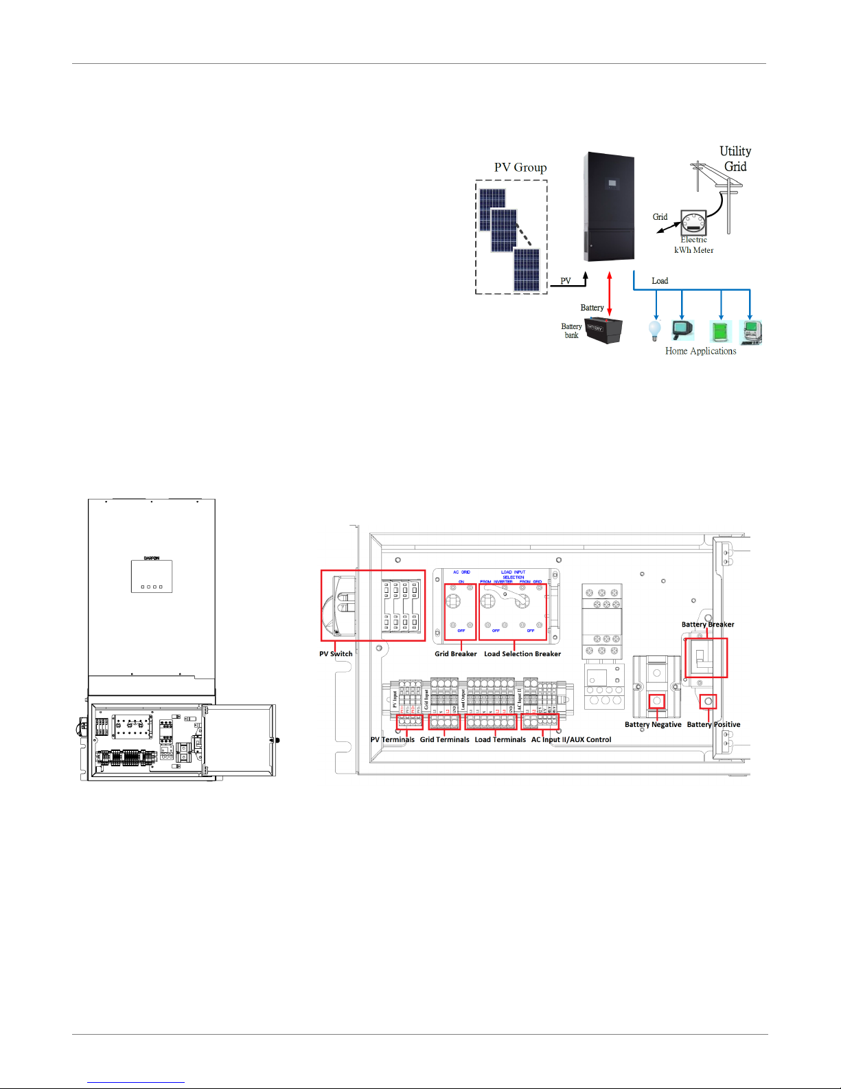
Product Overview................................................................................................................................ 4
MOUNTING THE INVERTER...............................................................................................................5
Installing the Inverter onto the Wall ............................................................................................... 5
PV MODULE (DC) CONNECTION .....................................................................................................6
Connecting the PV Arrays ................................................................................................................ 6
GRID (UTILITY) CONNECTION ..........................................................................................................7
Connecting to the Grid/Utility ...........................................................................................................7
BATTERY CONNECTION AND CHARGING REQUIREMENTS....................................................8
Connecting the Batteries .................................................................................................................. 8
Battery Charging Requirements...................................................................................................... 9
LOAD (AC OUTPUT) CONNECTION ...............................................................................................11
Connecting to the Load.....................................................................................................................11
OPERATION AND DISPLAY PANEL ...............................................................................................12
Display Panel Overview....................................................................................................................12
Starting the System............................................................................................................................12
Stopping the System .........................................................................................................................12
LCD Screen – Icons and Pages .....................................................................................................13
Mode Rule Definition.........................................................................................................................14
System Settings ..................................................................................................................................15
Warning and Fault Definition........................................................................................................... 17
GENERATOR [OPTIONAL] ................................................................................................................19
Generator Sizing.................................................................................................................................19
Automatic Start Generator...............................................................................................................19
Generator Application Schematic..................................................................................................19
CONFIGURING THE HARDWARE ..................................................................................................20
Connecting to the hardware ..........................................................................................................20
USE APPLICATION SOFTWARE MODIFIES PARAMETERS..................................................... 22
Preparation..........................................................................................................................................22
Connecting to the application software and modifies parameters .....................................22
Parameters setting tables ...............................................................................................................25
MAINTENANCE & CLEANING........................................................................................................ 26.
Wiring Diagram ..................................................................................................................................26
SPECIFICATIONS .............................................................................................................................. 27
GRID SUPPORT PARAMERTERS ................................................................................................... 28
5-YEAR LIMITED WARRANTY ........................................................................................................ 30

INSTALLATION MANUAL H5001 HYBRID INVERTER
Rev.1 ©2018 Darfon Electronics Corp. 3| Page
IMPORTANT SAFETY WARNINGS
PLEASE READ ALL INSTRUCTIONS AND CAUTIONARY MARKINGS ON THE UNIT AND THIS MANUAL BEFORE USING THE
INVERTER. AND, STORE THIS USER MANUAL WHERE IT CAN BE ACCESSED EASILY.
This manual is for qualified personnel. The tasks described in this manual may be performed by qualified personnel only.
Safety Symbols
WARNING. This indicates the risk of electric shock. The presence of high voltage levels may constitute a risk of injury or death to users
and/or installers.
CAUTION. This indicates important information where failure to comply may result in safety hazards or cause damage to this product.
CAUTION. This indicates the risk of a hot surface. The surface may reach a temperature high enough to cause serious burn injuries.
General Precautions
CAUTION. Before installing and using this inverter, read all instructions and cautionary markings on the inverter and all appropriate
sections of this guide. Installing this inverter by licensed electricians only.
CAUTION. Normally grounded conductors may be ungrounded and energized when a ground fault is indicated.
CAUTION. This inverter is heavy. It should be lifted by at least two persons for the safety.
WARNING. Authorized service personnel should reduce the risk of electrical shock by disconnecting AC, DC and battery power from the
inverter before attempting any maintenance or cleaning or working on any circuits connected to the inverter. Turning off controls will not
reduce this risk. Internal capacitors can remain charged for 5 minutes after disconnecting all sources of power.
WARNING. Do not disassemble this inverter yourself. It contains no user-serviceable parts. Attempt to service this inverter yourself may
cause a risk of electrical shock or fire and will void the warranty from the manufacturer.
WARNING. To avoid a risk of fire and electric shock, make sure that existing wiring is in good condition and that the wire is not
undersized. Do not operate the Inverter with damaged or substandard wiring.
CAUTION. Under high temperature environment, the cover of this inverter could be hot enough to cause skin burns if accidentally
touched. Ensure that this inverter is away from normal traffic areas.
WARNING. To avoid a risk of the inverter damage, make sure that the working areas no metal particle and keep clean around the
working areas.
WARNING. Use only recommended accessories from installer. Otherwise, not-qualified tools may cause a risk of fire, electric shock, or
injury to persons.
CAUTION. To reduce risk of fire hazard, do not cover or obstruct the cooling fan.
CAUTION. Do not operate the Inverter if it has received a sharp blow, been dropped, or otherwise damaged in any way. If the Inverter is
damaged, call for an RMA (Return Material Authorization).
CAUTION. This inverter is not allowed to operate in parallel. Do not parallel connect more than one unit in AC output connector.
Otherwise, it will damage this inverter.

INSTALLATION MANUAL H5001 HYBRID INVERTER
Rev.1 ©2018 Darfon Electronics Corp. 4| Page
INTRODUCTION
The H5001 hybrid inverter provides power to the essential
load by utilizing power from PV panels, the utility and
batteries. When the PV panels (two string input) generates
enough power, the inverter supports the essential load,
feeds back to the grid and charges the batteries, all at the
same time. When the energy generated by the PV panels is
not sufficient to support the essential load, the inverter takes
power from the utility.
To accommodate various power situations, the H5001 is
designed to handle continuous power from PV panels,
batteries and the utility. When the MPP input voltage from
the PV panels is within the acceptable range, between 250
and 430VDC, the inverter is able to feed the grid and charge
the batteries. This inverter is only compatible with single
crystalline and polycrystalline PV panels, and any other type of PV panels cannot be used.
Notes: When PV input voltage is lower than 250V, the power of the inverter will de-rate. This hybrid inverter has two PV
input.
Product Overview
Distribution Box
A wiring subpanel is pre-assembled at the factory. It consists of breakers, disconnects and batteries paralleled
circuits.
BASIC HYBRID PV STORAGE SYSTEM OVERVIEW

INSTALLATION MANUAL H5001 HYBRID INVERTER
Rev.1 ©2018 Darfon Electronics Corp. 5| Page
MOUNTING THE INVERTER
Before installation, make sure nothing inside the package is damaged. You should have received the following
items in the package: H5001 hybrid inverter, backplate, brackets, screws and this installation manual.
The following considerations must be taken into account before selecting where to install.
•The unit cannot be mounted on flammable construction materials.
•The unit must be mounted to a solid surface.
•The unit should be installed at eye level in order to easily read the LCD display at any time.
•Allow 20cm (8in) of clearance to the sides and 50cm (20in) to the top and bottom of the unit for proper air
circulation to dissipate heat.
•The ambient temperature must be between 0 and 50°C and relative humidity must be between 5 and 85% to
ensure optimal operation. Do not operate where the temperature and humidity are beyond the specified limits.
•The unit has a Pollution Degree rating of PD2. The unit must be mounted in a protected area that is dry, free of
excessive dust and has adequate air flow.
•The unit was designed with an IP20 protection rating and is for indoor applications only.
CAUTION. This inverter is heavy (87lb/40kg). Be carefully while lifting and mounting the unit. Installation should be
handled by two people. Do not hang or place additional weight onto the inverter.
Installing the Inverter onto the Wall
Step 1. Use the backplate as a
template, and install
anchors as needed.
Note: If installing onto
drywall, Unistrut needs to
be mounted and secured to
two studs in the wall. The
backplate and inverter’s
brackets are secured to the
Unistrut using Unistrut lugs.
Step 2. Mount the backplate onto the wall.
Note: Use at least two screws, one on
the left the other on the right.
Step 3. Install the brackets onto each
side of the inverter.
Step 4. Hang the inverter onto the
backplate.
Step 5. Secure the brackets on
inverters to the wall.
Note: Use at least two screws,
one on each side of the
inverter.

INSTALLATION MANUAL H5001 HYBRID INVERTER
Rev.1 ©2018 Darfon Electronics Corp. 6| Page
PV MODULE (DC) CONNECTION
There is a DC (PV) circuit breaker in the distribution box. This system can connect to two strings of PV modules with
MPPT control. Configure each PV input as recommended in the table below. Vmp is a PV panel’s max power point
voltage. The PV charging efficiency is maximized when the PV system’s voltage is close to Best Vmp.
TERMINAL MARK
PV INPUT POWER
TYPICAL AMPERAGE
CABLE SIZE
TORQUE
BEST VMP
VMP RANGE
PV input 1
3.25kW
13A
12 AWG
1.4 - 1.6 Nm
360V
250V - 430V
PV input 2
3.25kW
13A
12 AWG
1.4 - 1.6 Nm
360V
250V - 430V
WARNING. Because this inverter is non-isolated, only two types of PV modules are acceptable: single crystalline and poly
crystalline with only Class A-rated. To avoid any malfunction, do not connect any PV modules with possibility of leakage
current to the inverter. For example, non-grounded PV modules will cause leakage current to the inverter.
CAUTION. To reduce the risk of damage due to surge, Darfon recommends surge protection between the modules and
the inverter.
CAUTION. To reduce the risk of injury, use the proper cable size for PV module connection.
CAUTION. Exceeding the maximum input voltage can destroy the unit. Check the PV string voltage before wiring the
connection.
Connecting the PV Arrays
Step 1. For each PV input string, make sure the input voltage is between
250VDC and 430VDC, and the maximum current is 13A.
Note: The inverter can still be installed if you are only using
one PV input string.
Step 2. Make sure the circuit breaker is off.
Step 3. Strip 15mm(0.6in) of insulation from each PV cable (PV1+, PV1-, PV2+
and PV2-).
Step 4. Insert the PV cables into the PV quick connect terminals. Make sure
the polarity for each connection is correct; positive to positive and
negative to negative.
WARNING. Never touch the terminals of the inverter directly. It
will cause lethal electric shock.
WARNING. The final connection for DC strings should be done
at the array not at the inverter.
DC CABLE FOR PV CONNECTIONS
CONNECTING TO PV MODULE

INSTALLATION MANUAL H5001 HYBRID INVERTER
Rev.1 ©2018 Darfon Electronics Corp. 7| Page
GRID (UTILITY) CONNECTION
There is an AC (Grid) circuit breaker in the distribution box. This will ensure the inverter can be safely disconnected
during maintenance and is fully protected from overcurrent of AC input.
AC GRID
UTILITY
TYPE
USA: 240V/120V SPLIT-PHASE SYSTEM
EURO: 230V SINGLE PHASE SYSTEM
GRID CONNECTION
WIRING REQUIREMENTS
GRID RATED POWER
NOMINAL VOLTAGE
WIRE SIZE
TORQUE
5KW
230/240 VAC
8 AWG
0.82 Nm
WARNING. To reduce the risk of injury, use the recommended wire size above. It is very important for system safety and
efficient operation to use the appropriate wire for grid (utility) connection.
WARNING. To prevent the risk of electric shock, make sure the ground wire is properly earthed before operating this unit
whether the grid is connected or not.
Connecting to the Grid/Utility
Step 1. Check the grid voltage and frequency with an AC voltmeter. It
should be within the operation AC voltage range of the product’s
specifications.
Step 2. Make sure the circuit breaker is off.
Step 3. For each AC wire, strip 15mm(0.6in) of isolation.
Step 4. Connect the AC wires to the inverter according to the labels
indicated on the terminal block or your grid utility type.
Note: The PE protective conductor (Ground) should be the
first to be connected.
CONNECTIN G TO AC UTILITY TERMINAL
AC WIRE FOR GRID CONNECTION

INSTALLATION MANUAL H5001 HYBRID INVERTER
Rev.1 ©2018 Darfon Electronics Corp. 8| Page
BATTERY CONNECTION AND CHARGING REQUIREMENTS
There is a DC (Battery) circuit breaker in the distribution box. Before connecting the batteries, please have the
battery specifications on hand.
Notes: 1. For lead acid batteries, Flooded, Gel or AGM can be used. Please check maximum charging voltage and current
when first using this inverter.
2. If using Lithium batteries, consult with the battery manufacturer for details.
BATTERY POWER
TYPICAL AMPERAGE
BATTERY CAPACITY
CABLE LENGTH
CABLE SIZE
TORQUE VALUE
5KW
104A
200 to 600AH
< 3m (one-way)
2 AWG
2 to 3Nm (18 to 26 in-lb)
WARNING. To reduce the risk of injury, use the recommended cable size above. It is very important for system safety and
efficient operation to use the appropriate cable for battery connection.
Connecting the Batteries
Step 1. Make sure the circuit breaker is off.
Step 2. Make sure the nominal voltage for the batteries is 48VDC.
WARNING. Shock Hazard. Installation must be performed with
care due to high battery current.
Step 3. Strip 15mm(0.6in) of insulation from each battery cable and insert it
into a ring lug.
Step 4. Connect the battery ring lugs to the battery terminals. Make sure the polarity for each connection is correct; positive to
positive and negative to negative.
RED cable to the positive terminal (+);
BLACK cable to the negative terminal (-).
CAUTION. Before making the final DC connection or closing DC
breaker, make sure the connections have the correct polarity.
CAUTION. Do not apply anti-oxidant substance on the terminals
before terminals are connected tightly.
CAUTION. Do not place anything between the flat part of the inverter terminal and the ring terminal. Otherwise,
overheating may occur.
Step 5. Update AP registers as needed. Please refer to the remote setting (Page 28).
CABLES FOR BATTERY CONNECTION
CONNECTING TO BATTERY TERMINAL

INSTALLATION MANUAL H5001 HYBRID INVERTER
Rev.1 ©2018 Darfon Electronics Corp. 9| Page
Battery Charging Requirements
The default charging parameters are shown below. Use this as a reference to make sure the battery selected is
compatible with H5001 inverter. It is recommended that you use a deep cycle battery when the mode of operation
is not set as one of the two back-up modes. If you want to change battery charging parameters, please refer to the
remote setting on page 25.
1. Lead-Acid Battery Charging Characteristics(include non-conmunication batteries)
Charging Parameter
Default Value
Max. Charging Current 60A
Floating Charging Voltage
54Vdc
Absorption Charging Voltage 56Vdc
Charging process based on default setting.
The three stages:
First - charging voltage increases to 56V.
Second- charging voltage will maintain at 56V until charging current is down to 2 Amp.
Third- go to floating charging at 54V.
Bulk FloatingAbsorption
time
U
time
I
Bulk Voltage
Float Voltage

INSTALLATION MANUAL H5001 HYBRID INVERTER
Rev.1 ©2018 Darfon Electronics Corp. 10 | Page
2. Lithium Battery Charging Characteristics
Charging Parameter
Default Value
Max. Charging Current
60A
Golden Crown Battery Charging Voltage 56Vdc
Darfon Battery Charging Voltage
57.4Vdc
Panasonic Battery Charging Voltage 52Vdc
Charging process based on default setting.
The three stages:
First - charging voltage increases to Charging voltage.
Second- charging voltage will maintain until battery SOC is 99%.
Third- stop charging after 1 hour.
Bulk Absorption
time
U
time
I
Bulk Voltage
Float Voltage

INSTALLATION MANUAL H5001 HYBRID INVERTER
Rev.1 ©2018 Darfon Electronics Corp. 11 | Page
CONNECTING TO AC LOAD
LOAD (AC OUTPUT) CONNECTION
There are two AC circuit breakers inside the distribution box for the load connection; one for the load and the other
for grid bypass. These two breakers are interlocked (to ensure only one breaker will be active at a given time).
Note: If the inverter needs to be repaired, please turn on the AC breaker (from Grid), the Grid can continue to supply the load
when the inverter has been taken off.
AC LOAD
CONNECTION
TYPE
USA: 240V/120V SPLIT-PHASE SYSTEM
EURO: 230V SINGLE PHASE SYSTEM
AC OUTPUT MAX POWER
NOMINAL VOLTAGE
WIRE SIZE
TORQUE
5KW
230/240 VAC
8 AWG
0.82 Nm
WARNING. To reduce the risk of injury, use the recommended cable size above. It is very important for system safety and
efficient operation to use the appropriate cable for AC connection.
Connecting to the Load
Step 1. Make sure the circuit breaker is off.
Step 2. For each AC wire, strip 15mm(0.6in) of isolation.
Step 3. Connect the wires according to the labels indicated on the terminal
block or your grid utility type.
Step 4. Be sure to connect PE protective conductor first.
CAUTION. Make sure the AC Load and AC Grid are properly
connected. Misconnecting them will damage to this product.
AC WIRE FOR LOAD CONNECTION

INSTALLATION MANUAL H5001 HYBRID INVERTER
Rev.1 ©2018 Darfon Electronics Corp. 12 | Page
OPERATION AND DISPLAY PANEL
Display Panel Overview
The display panel consists of four function keys and an LCD screen. The display panel will be used to manage and
monitor the system.
Starting the System
Step 1. Make sure all the connections have been completed and
properly installed.
Step 2. Turn/set the PV Switch, Grid Breaker and Battery Breaker to
the on position.
Step 3. Turn on the Main Switch (located on the left side of the
inverter).
Step 4. If the inverter has multiple sources of power or just a PV or
grid connection, the inverter will start automatically. If the
battery is the only power source, then press the enter key for
3 seconds until two beeps are heard to start the inverter.
Step 5. Check AC output voltage: L-L 240Vac / L-N 120Vac. /L-N
230Vac
Step 6. Turn on Load Breaker in the distribution box.
Stopping the System
Step 1. Turn off the Main Switch (Located on the left side of the inverter).
Step 2. Turn off all power switch and breakers.
ICON
FUNCTION
DESCRIPTION
Enter
Confirm the selection in setting mode or
enter setting mode.
ESC
Exit Exits setting mode.
Left
Go to previous page, move or decreasing
all Number.
Right
Go to next page; move; to increase all
Number.

INSTALLATION MANUAL H5001 HYBRID INVERTER
Rev.1 ©2018 Darfon Electronics Corp. 13 | Page
LCD Screen – Icons and Pages
The LCD screen will display three different pages: “Power Flows”, “Power Information” and “System Settings”. Use
the ←or →keys to toggle between the various pages. The screen will default to the “Power Flows” page.
POWER FLOWSPAGE
POWER INFORMATION PAGE
SYSTEM SETTINGS PAGE
ICON
DESCRIPTION
Represents the PV Array
Represents the Battery Pack
Represents the Utility
Represents the Load
Represents the Hybrid Inverter
Indicates the Connection to a PC
Indicates the Error and error codes
Indicates an overload has occurred
Represents the System Mode Setting
Represents the System Time Setting
Represents the System Information
Today’s
Time

INSTALLATION MANUAL H5001 HYBRID INVERTER
Rev.1 ©2018 Darfon Electronics Corp. 14 | Page
Mode Rule Definition
This hybrid inverter has six modes of operation for backup, residential and time of use. Each mode assumes a set of
conditions and prioritizes the consumption of PV, Grid or batteries accordingly to optimize energy flow.
Note: *1 The default feed-in power is 3000W.
PRESET MODES
PV USE PRIORITY
LOAD PRIORITY
CHARGE FROM
FEED GRID FROM
BATTERY DOD
Load Batt. Grid PV Grid Batt. PV Grid PV
Batt.
(No PV)
On-Grid Off-Grid
1. Back-up (default)
2
1
3
1
2
3
Ye s
Ye s
Ye s
No
40%
0%
2. Residential
1
2
3
1
3
2
Ye s
No
Ye s
No
40%
0%
3. Back-up w/o Feed-in
2
1
X
1
2
3
Ye s
Ye s
No
No
40%
0%
4. Residential w/o Feed-in
1
2
X
1
3
2
Ye s
No
No
No
40%
0%
5. TOU w/o Batt.
Feed-in
Low electricity cost
2
1
3
1
2
3
Ye s
Ye s
Ye s
No
40%
0%
High electricity cost
1
2
3
1
3
2
Ye s
No
Ye s
No
40%
0%
6. TOU w/ Batt.
Feed-in
Low electricity cost
2
1
3
1
2
3
Ye s
Ye s
Ye s
Ye s
40%
0%
High electricity cost
1
3
2
1
3
2
Ye s
No
Ye s
Ye s
40%
0%
PRESET MODES
DESCRIPTION
1. Back-up (default)
Keep the battery full and discharge the battery only if power outage happens.
2. Residential
Reduce power consumption from the Grid. Use the power from PV and battery first.
3. Back-up w/o Feed-in
Operate as Back-up mode but will not feed-in power back to the Grid.
4. Residential w/o Feed-in
Operate as Residential mode but will not feed-in power back to the Grid.
5. TOU w/o Batt.
Feed-in
Low electricity cost
Operate as Back-up mode.
High electricity cost
Operate as Residential mode.
6. TOU w/ Batt.
Feed-in
Low electricity cost
Operate as Back-up mode.
High electricity cost
*1Operate as Residential mode and will feed-in constant power back to the Grid.
Backup mode
in off-grid
operation
Backup mode
in grid-tied
operation
Residential mode
in grid-tied
operation
Primary
route
Secondary
route
TOU mode during
peak period
TOU mode during
off-peak period

INSTALLATION MANUAL H5001 HYBRID INVERTER
Rev.1 ©2018 Darfon Electronics Corp. 15 | Page
System Settings
In the display panel, use ←or →keys to get to the System Setting Page. System settings are divided into two parts,
“Mode” and “Time Setting.” Click to enter the System Setting Page and click ESC to exit.
A. Selecting/Changing Modes
Step 1.
In the System Setting Page,
press twice to enter the
page to select Mode.
Step 2.
Enter the password 9999. Use
the ←or →keys to change the
number, and then to set it.
If you get an incorrect password
message, please confirm you have
the correct password and try again.
Step 3.
Use the
←
or
→
keys to
toggle between modes and
to select it. (See mode
definitions on page 14)
Step 4.
For modes “Time of Use” or “Time of Use with Battery Feed-in”, enter the
start/end times for “High Price Duration” in 24-hour notation. Use the ←
or →keys to change the number, and then to set it. Once the value
for the last time field is set, press the key.
Step 5. Settings are being updated.
Please wait for next
massage.
Step 6. Press any key and manually
restart with the main switch
located on the leftside of the
inverter.
If you get a setting fail message, press
any key. Please re-turn on the main
switch
and re-setting the mode again. I
f still get a
setting fail message, please contact your
Darfon representative.
Start Time
End Time

INSTALLATION MANUAL H5001 HYBRID INVERTER
Rev.1 ©2018 Darfon Electronics Corp. 16 | Page
B. Setting System Time
In the System Setting Page, press →to select “Time Setting”, and then press .
The date format is DD/MM/YYYY, and the time format is hh:mm:ss.
Use the key to toggle between the date fields and the ←or →
keys to select the values. Once the value for the last date field is set,
press the key. You will then be prompted to enter the password.
Go see password section on page 15 for details.
YEAR RANGE
MONTH RANGE
DAY RANGE
HOUR RANGE
MINUTE RANGE
SECOND RANGE
2010 to 2100
1 to 12
1 to 31
0 to 23
0 to 59
0 to 59
C. Setting Battery Type.
Step 1.
In the System Setting Page,
press to enter the page
and select to select
Battery Type.
Step 2.
Enter the password 1111. Use the
←or →keys to change the
number, and then to set it.
If you get an incorrect password
message, please confirm you have
the correct password and try again.
Step 3.
Use the
←
or
→
keys to
select Battery Type and
to select it.
Step 4.
Use the
←
or
→
keys to Press any key and manually
toggle between battery types restart with the main switch
and press to select it. located on the leftside of the
(See Battery Type definitions inverter.
on page 25)

INSTALLATION MANUAL H5001 HYBRID INVERTER
Rev.1 ©2018 Darfon Electronics Corp. 17 | Page
Warning and Fault Definition
On the Power Flows Page, the icon will flash when an error has occurred. Listed below are the error codes
and their solutions.
CODE
FAULT E VEN T
ALARM
SOLUTION
01
DC bus voltage exceeds the upper threshold
Non-action
1. Shut down the system completely.
2. Restart the system to see if it’s ok.
3. If error message still remains, please contact your installer.
02
Arc occurs on PV
Non-action
03
DC bus voltage falls below the lower threshold
No-action
04
A relay fault event is detected
No-action
05
Battery discharging current exceeds the upper
threshold
ON – 1sec
OFF – 1sec
07
Battery charging current exceeds the upper
threshold
ON – 1sec
OFF – 1sec
08
Short circuit on PV1 input
No-action
09
Short circuit on PV2 input
No-action
10
Short circuit on inverter output
Always ON
11
Leakage current CT fault
No-action
12
DC/DC OP Current Sensor fault
No-action
13
Inverter OP Current Sensor fault
No-action
14
PV OP Current Sensor fault
No-action
15
EEProm read failure
No-action
16
Over temperature fault
ON – 1sec
OFF – 1sec
4. The internal temperature is higher than specified temperature.
5. Leave system to be cooled to room temperature.
6. If the error message still remains, please contact your installer.
17
PV input voltage exceeds the upper threshold
No-action
7. Check if the open circuit voltage of PV modules is higher than
500VDC.
8. If PV open circuit voltage is less than 500VDC and the error message
remains, pelase contact your installer.
18
Auxiliary power* failed
*Auxiliary power means switch power supply.
9. Turn off the system.
10. Then, restart the system.
11. If the error message still remains, please contact your installer.
19
PV insulation resistance is too low
No-action
12. Check if the impedance between positive and negative poles to
the ground is greater than 1MΩ.
13. If the impedance is lower than 1MΩ, please contact your installer.
20
Charging voltage is too high
No-action
14. Check if the connection between battery and inverter is well.
15. Make sure battery condition is ok.
16. Then, restart the inverter.
17. If error message remains, please contact your installer.
21
Fan fault
No-action
18. Please check if fans are runing ok.
19. If fans are runing ok, please shut down inverter first and then,
restart it.
20. If fans are stop runing or error message remains after restart the
inverter, please contact your installer.

INSTALLATION MANUAL H5001 HYBRID INVERTER
Rev.1 ©2018 Darfon Electronics Corp. 18 | Page
On the Power Flows Page, the icon will flash when an overload has occurred.
On the Power Flows Page, the icon will flash when there is a warning. Listed below are the warning codes
and their solutions.
CODE
FAULT E VEN T
ALARM
SOLUTION
22
Overload
ON – 0.25sec
OFF – 0.75sec
21. The output power is higher than 5500W.
22. If the output power is between 5500W and 7500W, the system will shut down
after 40 seconds and restart. If the system shut down 3 times it will not restart again.
23. If the output power is higher than 7500W, the system will shut down after 1
second but not restart.
23
PV Input Overpower
No-action
24. Shut downthe system completely.
25. Restart the system to see if it’s OK.
26. If error message still remains, please contact your installer.
CODE
WARNING
SOLUTION
51
Data saving fault.
27. Shut down the system completely.
28. Restart the system to see if it’s ok. If error message still remains, please
contact your installer.
52
Input PV is found lost.
53
PV input voltage reads low.
29. Check if the open circuit voltage of PV modules is higher than
500VDC.
30. If PV open circuit voltage is less than 500VDC and the error message
remains, pelase contact your installer.
54
Power island
31. Shut down the system completely.
32. Restart the system to see if it’s ok. If error message still remains, please
contact your installer.
55
Grid is disconnected.
56
Power grid voltage exceeds the upper threshold
57
Power grid frequency falls below the lower threshold
58
Power grid frequency exceeds the upper threshold
59
Power grid frequency falls below the lower threshold
60
DC injection fault
61
Battery voltage is too low.
33. The battery voltage is less than 42V.
34. Wait PV or Grid to charge up the battery.
62
Low battery
35. Battery capacity is < 30% or battery voltage is < 45.6V.
36. Wait for PV or Grid to charge the battery.
63
Battery is disconnected.
37. Shut down the system completely.
38. Check if the battery is connected firmly.
39. Restart the system to see if it’s ok. If error message still remains, please
contact your installer.
64
Inverter output OCP
40. Shut down the system completely.
41. Restart the system to see if it’s ok. If error message still remains, please
contact your installer.
Alarm Buzzer: ON – 1sec, OFF – 1sec
65
RS485 communication fault
42. Shut down the system completely.
43. Restart the system to see if it’s ok. If error message still remains, please
contact your installer.
66
Output de-rating
44. When system temperature is too high, the output power is de-rating.
45. Lower the load or lower the environmental temperature.

INSTALLATION MANUAL H5001 HYBRID INVERTER
Rev.1 ©2018 Darfon Electronics Corp. 19 | Page
GENERATOR [OPTIONAL]
The inverter can only work with “split-phase” generators that delivers clean 120/240Vac at 60Hz. Single-phase and
three-phase generators are not compatible with this inverter.
Note: Generators installed in a building should not have a bond between the neutral and ground connections. Installations in
North America are expected to bond the neutral and ground at the main electrical panel.
Generator Sizing
•Available generator power may be limited by ratings for circuit breakers and/or generator connectors. The
maximum allowed AC circuit breaker size is 40A.
•The generator should be sized to provide enough power and current for all loads. The minimum recommended
generator wattage is 6.25kW becuase many generators may not be able to maintain AC voltage or frequency
for long periods of time if they are loaded more than 80% of rated capacity.
Automatic Start Generator
The inverter can provide a start signal to control an automatic start generator. The generator must be an
electric-start model with two-wire start capability. For other start-up methods, additional equipment may be
required.
The 12V and Relay AUX terminals are used to start an automatic generator.
•The 12V AUX terminals are a switched 12Vdc power supply and can supply up to 0.25A.
•The Relay AUX terminals are “dry” contacts with no voltage and can conduct up to 7A and up to 250Vac.
Function Signal Description
UNIT
CONDITION
12VDC SOURCE
DRY CONTACT
Power Off
Unit is off and no output is powered.
0 Vdc
Open
Power On
Grid
Available
Battery voltage < Battery cut-off discharge voltage
0 Vdc
Open
Battery voltage > Battery re-discharging voltage
0 Vdc
Open
Grid
Unavailable
Battery voltage < Battery cut-off discharge voltage
12Vdc
Close
Battery voltage > Battery re-discharging voltage
0Vdc
Open
Generator Application Schematic
On AC input II Terminal, there are 6 pin for control Generator. Control port have defined as 1) Generator Power Line,
2) dry contact and 3) 12VDC source and. It could be used to remote control for external generator.

INSTALLATION MANUAL H5001 HYBRID INVERTER
Rev.1 ©2018 Darfon Electronics Corp. 20 | Page
CONFIGURING THE HARDWARE
Connecting to the hardware
Step1: Remove the eleven screws on the bottom sides of the inverter.
There are two PCB boards,
1. Left side: Communication board is used for parallel and display communication.
2. Right side: External RS485 board is used for master RS485 (communicated with battery) and slave RS485
(communicated with application software & data-logger).
FUNCTION DESCRIPTION
REMARKS
1.
AUX. PORT
FOR GENERATION FUNCTION
2.
EXTERNAL DISPLAY PORT
FOR H100/H200 CABINET USE
3.
PARALLELED COMMUNICATION PORT
FOR H5001 PARALLELED FUNCTION
4.
BOOT-LOAD AND COMMUNICATION JUMPER.
5.
USB PORT
6.
RS-485 SLAVE
FOR DATA LOGGER USE/REMOTE CONTROL USE
7.
RS-485 MASTER
FOR BMS USE
Communication board
External RS485 board
①
②
③
④
⑤
⑥
⑦
Other manuals for H5001
2
Table of contents
Other Darfon Inverter manuals

Darfon
Darfon HB51 User manual

Darfon
Darfon G320 User manual

Darfon
Darfon MIG240UL00 User manual

Darfon
Darfon MIG240 User manual

Darfon
Darfon MIG300 User manual

Darfon
Darfon H5001 User manual

Darfon
Darfon PVI5000 User manual

Darfon
Darfon G640 User manual

Darfon
Darfon H5001 User manual

Darfon
Darfon H5000 User manual