preis WRCS III User manual

WRCS III
User Manual 1.5
Preis Ingenieurbüro GmbH 18.08.2021 Page 1
WRCS III
Wide Range Current Sensor
User Manual
Version 1.5 –18.08.2020

WRCS III
User Manual 1.5
Preis Ingenieurbüro GmbH 18.08.2021 Page 2
Content
1 Block diagram.................................................................................................................................. 3
2 User Interface.................................................................................................................................. 4
2.1 Display ..................................................................................................................................... 5
2.2 Rotary encoder........................................................................................................................ 5
2.3 BNC Output Common .............................................................................................................. 5
2.4 BNC Output A, B, C .................................................................................................................. 5
2.5 Load current connection ......................................................................................................... 5
3 Menu navigation ............................................................................................................................. 6
3.1 Main menu .............................................................................................................................. 6
3.2 Menu “Filter”........................................................................................................................... 7
3.3 Menu “Output”........................................................................................................................ 8
3.4 Menu “Out Com”..................................................................................................................... 8
3.5 Menu “Out A”, “Out B”, “Out C” ............................................................................................. 9
3.6 Menu Protection ..................................................................................................................... 9
3.7 Menu Fuse............................................................................................................................. 10
3.8 Menu Screen Saver................................................................................................................ 10
3.9 Menu Version........................................................................................................................ 11
4 Function of “Common”-Output..................................................................................................... 12
5 Overcurrent protection ................................................................................................................. 13
6 Reverse polarity protection........................................................................................................... 13
7 Technical specification .................................................................................................................. 14

WRCS III
User Manual 1.5
Preis Ingenieurbüro GmbH 18.08.2021 Page 3
1Block diagram
12.8uA
Range: 1mA
Filter: 1ms
10A 10A 100A
Shunt
electronic
Switch
ADC
DSP
Filter
DAC
DAC
DAC
DAC
Isolation
Isolation
12V Power Supply
WRCS III
User Manual 1.5
Preis Ingenieurbüro GmbH 18.08.2021 Page 4
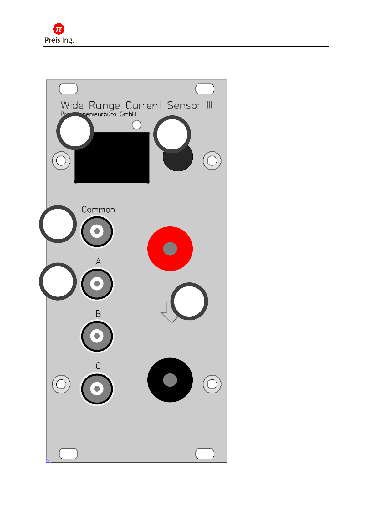
2User Interface
12.8uA
Range: 1mA
Filter: 1ms
10A 10A 100A
1
2
3
4
5

WRCS III
User Manual 1.5
Preis Ingenieurbüro GmbH 18.08.2021 Page 5
2.1 Display
The OLED display shows the actual current and settings.
2.2 Rotary encoder
Select the menu by pressing the knob.
Change settings by rotating the knob.
2.3 BNC Output Common
Current value from 0 .. 200A results in an output voltage of 0 .. 6.2V. Each decade from 1mA to 100A
is 1V on the output. For detailed curves see chapter Function of “Common”.
2.4 BNC Output A, B, C
Current value output as voltage from 0..1V or 0..10V. Configurable by Menu setting “Output”.
The voltage range of the analog digital converters is always 0 .. 10V. By using the 1V range, only 10%
of the analog range is used resulting in higher quantization noise. For better accuracy and better
signal to noise ratio use the 10V range. The 1V range only is implemented for compatibility to current
systems.
2.5 Load current connection
The load current has to flow through the pole terminals in direction of the arrow (from top/red to
bottom/black).
For continuous load currents >70A a minimum wire size of 35mm² is mandatory to avoid additional
heat input from the hot wires into the device.
The connection between the pole terminals is in a high impedance state, if the WRCS III is switched
off. The internal switch has a dielectric withstanding voltage of 55V.
WRCS III
User Manual 1.5
Preis Ingenieurbüro GmbH 18.08.2021 Page 6
3Menu navigation
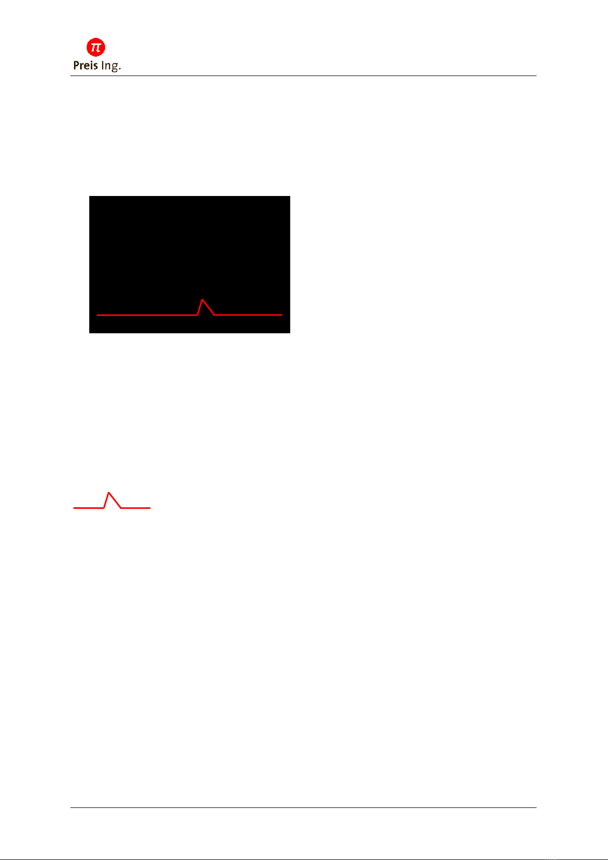
3.1 Main menu
12.8uA Actual measured current
Range: 1mA Actual measurement range
Filter: 1ms Filter time constant of a digital PT1 filter. Adjustable in menu “Filter”.
10A 10A 200A Measurement range of the 3 outputs A, B, C. Configurable in the menus
“Out A”, “Out B”, “Out B”.
Temporal course of the current. The graph shows the relative current in the
current measurement range. If the range changes to the next range, the color of the graph toggles
between red and orange.
12.8uA
Range: 1mA
Filter: 1ms
10A 10A 200A
WRCS III
User Manual 1.5
Preis Ingenieurbüro GmbH 18.08.2021 Page 7
3.2 Menu “Filter”
Filter time constant of the digital PT1 (IIR)-Filter.
It is recommended to select a filter time, which is higher than the sample interval of the connected
multimeter/data logger to avoid aliasing.
Additionally, a wrong setting may result in an offset error because of the nonlinear characteristic
curve of the COM output.
Possible settings:
No Filt –ADC-data is put out unfiltered
100µs
1ms
10ms
100ms
1s
10s
Filter time constant
3dB cutoff frequency
No Filt
≈6kHz analog bandwith
100µs
1,59 kHz
1ms
159 Hz
10ms
15,9Hz
100ms
1,59Hz
1s
0,159Hz
10s
0,0159 Hz
Filter
100us

WRCS III
User Manual 1.5
Preis Ingenieurbüro GmbH 18.08.2021 Page 8
3.3 Menu “Output”
Current value at the outputs A, B, C. Set to 0..1V or 0..10V.
The voltage range of the analog digital converters is always 0 .. 10V. By using the 1V range, only 10%
of the analog range is used resulting in higher quantization noise. For better accuracy and better
signal to noise ratio use the 10V range. The 1V range only is implemented for compatibility to current
systems.
Possible settings:
0..1V
0..10V
3.4 Menu “Out Com”
Activates/deactivates the common output. For a very fast output of the current value, the output
sample frequency can be increased to 50kHz by using only one output channel.
Possible settings:
-off-
-on-
Output
0..1V
Out Com
-on-

WRCS III
User Manual 1.5
Preis Ingenieurbüro GmbH 18.08.2021 Page 9
3.5 Menu “Out A”, “Out B”, “Out C”
Setting of the measurement range for the outputs A,B or C. Additionally the output can be disabled
to increase the output sample frequency to 50kHz.
Possible settings:
-off-
1mA
10mA
100mA
1A
10A
100A
200A
3.6 Menu Protection
Possible settings:
-off- No self protection
Rev-Pol Reverse polarity protection
Overcur Overcurrent protection
-Both- Reverse polarity protection + overcurrent protection
You lose warranty if you disable the protection features.
Out A
100mA
Protect.
-Both-

WRCS III
User Manual 1.5
Preis Ingenieurbüro GmbH 18.08.2021 Page 10
3.7 Menu Fuse
When the set threshold is exceeded, the internal electronic circuit breaker interrupts the circuit. The
filter time set in the Filter menu is used as the trip time constant.
ATTENTION:
If voltages of more than 60V occur when the fuse triggers, this can lead to a defect of the device. This
must also be taken into account when measuring purely inductive loads.
3.8 Menu Screen Saver
Possible settings:
1 min
10 min
1 hour
10 hours
disabled
The display of the device is an OLED. This display technology tends to burn in the bright pixels during
long periods of operation. In order to reduce the aging of the display, especially during long
continuous operation over weeks, the screensaver should be activated. It dims the display to lower
brightness values after a short time.
The device has a presence detection function. If there is movement in front of the device, the
screensaver is deactivated and the display shows the measured value with full brightness. This
detection can also be triggered by people passing by, so that in continuous operation, short set times
achieve the greatest gain in display life.
ScrSaver
1 min
Fuse
25 A

WRCS III
User Manual 1.5
Preis Ingenieurbüro GmbH 18.08.2021 Page 11
3.9 Menu Version
Display of the software version und the maximum continuous current of the device.
Version
V1.5.1
90A max
www.preis-ing.com

WRCS III
User Manual 1.5
Preis Ingenieurbüro GmbH 18.08.2021 Page 12
4Function of “Common”-Output
The Outputs A, B and C are mapping a preselected measurement range to an output voltage from
0..10V (0..1V).
In contrast the “Common” output is able to map the complete measurement range of the device
from 0µA to 200A to the output. Every current decade is represented by a voltage rise of 1V.
Current range
Output voltage
Example current
Example voltage
0… 999.9µA
0… 999.9mV
250µA
0.250V
1.000mA … 9.999mA
1.1000V .. 1.9999V
2.5mA
1.250V
10.00mA … 99.99mA
2.1000V .. 2.9999V
25mA
2.250V
100.0mA … 999.9mA
3.1000V .. 3.9999V
250mA
3.250V
1.000A … 9.999A
4.1000V .. 4.9999V
2.5A
4.250V
10.00A … 99.99A
5.1000V .. 5.9999V
25A
5.250V
100.0A … 200.0A
6.1000V .. 6.2000V
125A
6.125V
You may interpret the output voltage also as exponential notation of the current.
The number before the decimal point from 0 to 6 represents the measurement range from 1mA to
200A. The decimal represents the current value of the measurement range.
Example:
3.250V
3 = range 1A .250 = 0.250 of 1A = 250mA
1mA
10mA
100mA
1A
10A
100A
0µA
5V
6V
0V
1V
2V
3V
4V
WRCS III
User Manual 1.5
Preis Ingenieurbüro GmbH 18.08.2021 Page 13
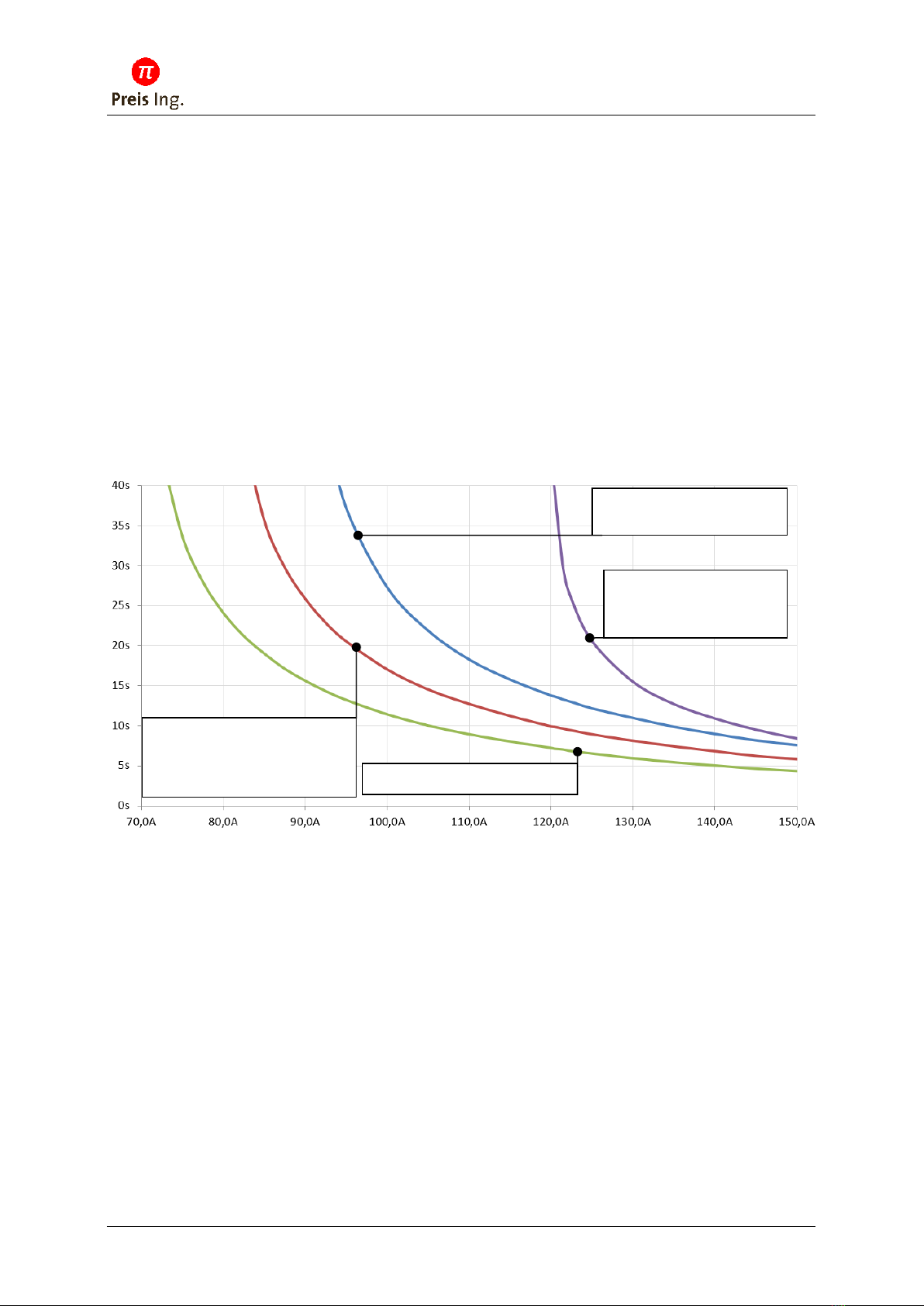
5Overcurrent protection
If the overcurrent protection is active, a thermo model protects the device against excessive current
draw and cuts the internal connection by an internal 60V MosFet switch. The permitted continuous
current depends on the hardware configuration and the housing. If the protection is deactivated, a
warning is displayed, if the trip current is exceeded.
Single device without internal fan : 70A
Single device with internal fan : 80A
Rack version without internal fan in rack with forced ventilation : 80A
Rack version with internal fan in rack with forced ventilation : 90A
Rack version with internal fan in rack with forced ventilation (since 10/2019) : 120A
The grayed variants are no longer in production.
At an overcurrent event, the device cuts off the current und protects itself.
To reactivate, press the rotary encoder.
6Reverse polarity protection
The reverse polarity protection prevents negative current.
If the reverse polarity protection is activated, the device cuts off the load circuit after a short time of
negative current draw. To reactivate, press the rotary knob.
If the reverse polarity protection is deactivated, continuous negative currents are possible.
The device internally selects the appropriate measurement range to protect the internal shunt
resistors against excessive power dissipation. The selection of the appropriate range by the
autorange logic after return to positive currents may take a while.
Rack version with internal fan
in rack with forced ventilation
Single device without internal fan
Single device with internal fan
Rack version without internal fan
in rack with forced ventilation
Version with internal fan in
rack with forced ventilation
since 10/2019

WRCS III
User Manual 1.5
Preis Ingenieurbüro GmbH 18.08.2021 Page 14
7Technical specification
Power supply: 12V +-1V
Current consumption: 90mA … 180mA
Max. continuous current: Single device without internal fan : 70A
Single device with internal fan : 80A
Rack without internal fan in rack with forced ventilation : 70A
Rack with internal fan in rack with forced ventilation : 90A/120A
The grayed variants are no longer in production.
Max. peak current 200A (2s)
Max. input voltage: 55V (in cutoff state/powerless state)
Galvanic isolated outputs: 100V max. potential difference
Dimensions single device: 260x68x39mm (including terminals)
Dimensions single rack: Width : 84 HP
Height : 4 U
Length : 375 mm
Dimensions dual rack: Width : 84 HP
Height : 7 U
Length : 375 mm
Shunt Resistance:
Measurement range
Resistance
1mA
100Ω
10mA
10Ω
100mA
1Ω
1A
100mΩ
10A
10mΩ
200A
0.5mΩ
Max. internal resistance 2.3mΩ between terminals in 200A range
Sample frequency: 50kHz / 20µs
Bandwidth: Up to 1.59kHz (adjustable)
Refresh rate DAC: 20µs per Channel
20µs, if one output channel active
80µs, if all 4 output channels active

WRCS III
User Manual 1.5
Preis Ingenieurbüro GmbH 18.08.2021 Page 15
Tolerance Channel Common:
Measurement range
tolerance*1
1mA
0.4%
10mA
0.4%
100mA
0.4%
1A
0.4%
10A
0.4%
200A
0.5%
Tolerance Channel A, B, C:
Measurement range
tolerance*1
1mA
0.4%
10mA
0.4%
100mA
0.4%
1A
0.4%
10A
0.4%
200A
0.5%
*1of the respective measurement range max. value
Address:
Preis Ingenieurbüro GmbH
Hauptstraße 4
77830 Bühlertal
Tel: 07223 283131-0
Fax: 07223 283131-7
www.preis-ing.de
Table of contents


