Preliminary UNIFLEX CI 45 User manual

FEATURES
ØCompact design, only 22,5 mm
wide
ØClips onto top-hat DIN rail
ØPlug-in screw terminals or
spring-clamp connectors
ØDual-line LC display with addi-
tional display elements
ØProcess values always in view
ØConvenient 3-key operation
ØDirect communication between
rail-mounted transmitters
ØUniversal input with high signal
resolution (>15 bits) - also re-
duces stock keeping
ØUniversal output with high reso-
lution (14 bits) as combined volt-
age/current output
ØQuick response; only 100 ms cy-
cle time, i.e. also suitable for fast
signals
ØOne or two relay outputs
ØCustomer-specific linearization
ØMeasurement value correction
(offset or 2-point)
ØMin/max indicator (‘slave
pointer’)
ØLogical linking of digital outputs,
e.g. for common alarms
ØPreset for output value
APPLICATIONS
±Measurement, scaling, and sepa-
ration of electrical signals, e.g.
for:
±Heat treatment plants
±Drying equipment
±Furnace builders
±Metallurgy
±Kilns
±General machine building
±Research and development
±etc.
DESCRIPTION
UNIFLEX CI 45 transmitters are desig-
ned to give precise and cost-effective
signal detection and processing tasks.
Every CI 45 has at least one universal
input, one universal output and a relay.
Optionally, the transmitter can be fit-
ted with an additional relay.
Galvanic isolation is provided between
inputs and outputs as well as from the
supply voltage and the communication
interfaces.
Mounting
The compact CI 45 is clipped onto a
top-hat DIN rail, and can also be un-
mounted very simply.
All connections are of the plug-in type,
so that a transmitter can be replaced
very quickly without disturbing the wi-
ring.
Display and operation
The two-line LC display permits simul-
taneous indication of the measured va-
lue and all of the unit’s operating
functions.
Moreover, a LED and 4 other display
elements give a reliable indication of
operating status, operating mode, and
error messages.
The user-configurable engineering unit
of the measured value can be included
in the display. By means of the exten-
ded Operating Level, it is possible to
show any signal or parameter in the
2nd display line.
Interfaces and Engineering Tools
The transmitter settings are also confi-
gurable by means of an Engineering
Tool.
Via the BlueControl®software, inclu-
ding the transmitter simulation and
especially the convenient connection
via the BluePort®front interface, the
user can solve the task in hand wit-
hout having to work through operating
instructions.
Of course, practically all settings can
also be made from the device front.
UNIFLEX CI 45
Universal transmitter
Compact design
Display & operating functions
Communication features
High resolution
Fast cycle times
Universal input & universal output
Two relay outputs
Customer-specific linearization
Measurement value correction
Min/max indicator (‘slave pointer’)
rail line
Preliminary

Moreover, the CI 45 can exchange
data with superordinate systems and
PCs via an optional RS 485 interface
with MODBUS RTU protocol that is fit-
ted into the top-hat DIN rail.
Password protection
If required, unauthorized access to the
various Operating Levels can be pre-
vented with a password, or an entire
level can be blocked.
TECHNICAL DATA
INPUTS
Survey of inputs
Input Purpose
INP1 X1 (process value 1), universal
input
di1 Operation disabled; Reset of
stored alarms; Reset of min/max
indicator.
UNIVERSAL INPUT INP1
Resolution: > 15 bits
Decimal point: 0 to 3 decimals
Digital input filter: adjustable
0.0...999.9 s
Scanning cycle: 100 ms
Linearization: 31 segments,
adaptable with
BlueControl®
Measurement
value correction: 2-point or offset
Limiting frequency: 1,7 Hz
Thermocouples (Table 1)
Input resistance: ?1MW
Influence of source
resistance: 1 µV/W
Input circuit monitor: sensor break, polarity
Cold-junction compensation
Internal: for INP1
External: 0 ...100 °C
Additional error:
typ. ß_0,5 K
max. ß+ 2,4 K
Break monitoring
Sensor current: £1µA
Operating sense configurable
Resistance thermometer (Table 2)
Connection technique: 3 or 4-wire
Lead resistance: max. 30 W
(max. at range end)
Input circuit monitoring: break and short circuit
Measurement span
The BlueControl®software enables
the internal characteristic curve for the
KTY 11-6 temperature sensor to be
adapted.
Physical measurement range: 0...4500 W
Current and voltage
measurement (Table 3)
Span start and span: anywhere within the
measurement range
Scaling: freely selectable
–1999...9999
Input circuit monitoring
(current): 12,5% below span start
(2 mA)
2 UNIFLEX CI 45 - Preliminary-
Thermocouple type Measurement range Error Typical resol.
L Fe-CuNi (DIN) -100...900°C -148...1652°F £2K 0,05 K
J Fe-CuNi -100...1200°C -148...2192°F £2K 0,05 K
K NiCr-Ni -100...1350°C -148...2462°F £2K 0,1 K
N Nicrosil/Nisil -100...1300°C -148...2372°F £2K 0,1 K
S PtRh-Pt 10% 0...1760°C 32...3200°F £2K 0,1 K
R PtRh-Pt 13% 0...1760°C 32...3200°F £2K 0,1 K
T Cu-CuNi -200...400°C -328...752°F £2K 0,03 K
C W5%Re-W26%Re 0...2315°C 32...4199°F £3K 0,2 K
D W3%Re-W25%Re 0...2315°C 32...4199°F £3K 0,2 K
E NiCr-CuNi -100...1000°C -148...1832°F £2K 0,05 K
B * PtRh-Pt6% 0(400)...1820°C 32(752)...3308°F £3K 0,2 K
Special -25 … 75 mV £0,1% 0,005%
* Values apply from 400°C upwards.
Table 1: Thermocouple input
Type Sensor current Measurement range Error Typical resol.
Pt100 ***
ß0,25mA
-200...100 (150)°C -328...212 (302)°F £1 K 0,05 K
Pt100 -200...850°C -328...1562°F £1 K 0,05 K
Pt1000 -200...850°C -328...1562°F £2 K 0,05 K
KTY 11-6* -50...150°C -58...302°F £2 K 0,05 K
Special* 0...4500 W** £0,1% 0,005%
Special 0...450 W** £0,1% 0,005%
Potentiom. 0...160 W** £0,1% 0,005%
Potentiom. 0...450 W** £0,1% 0,005%
Potentiom. 0...1600 W** £0,1% 0,005%
Potentiom. 0...4500 W** £0,1% 0,005%
* Default setting is the characteristic for KTY 11-6 (-50...150°C)
** Including lead resistance
*** up to 150 °C at reduced lead resistance (max. 160 W)
Table 2: Resistive inputs
Measurement range Input resistance Error Typical resol.( )
0...10 V 110 kWß0,1 % 0,3 mV
-10...10 V 110 kWß0,1 % 0,6 mV
-5...5 V 110 kWß0,1 % 0,3 mV
-2,5...115 mV* >1MWß0,1 % 4 úV
-25...1150 mV* >1MWß0,1 % 40 úV
-25...90 mV* >1MWß0,1 % 4 úV
-500...500 mV* >1MWß0,1 % 40 úV
-200...200 mV* >1MWß0,1 % 20 úV
0...20 mA 20 Wß0,1 % 0,8 úA
* For INP1: high-impedance, without break monitoring
Table 3: Current and voltage input

CONTROL INPUT DI1
Configurable as direct or inverse switch
or contact!
Connection of potential-free contact that
is suitable for switching ‘dry’ circuits.
Switched voltage: 5 V
Switched current: 1 mA
OUTPUTS
SURVEY OF OUTPUTS
Output Purpose
OUT1 OUT2
(relay)
Limit contact, alarms *
OUT3
(logic)
Same as OUT1 and
OUT2
OUT3
(continuous)
Analog output
(display value, INP1)
Transmitter supply
13V/22mA
*All logic signals can be ”OR-linked”.
RELAY OUTPUTS OUT1, OUT2
Type: 2 NO contacts with a
common terminal
Max. contact rating: 500 VA,
max. 250 V, max. 2 A
at 48...62 Hz,
resistive load
Min. contact rating: 6V, 1 mA DC
Service life (electrical): 800.000 switching cycles
at max. rating
Note:
If the relays OUT1 and OUT2 operate
external contactors, these must be fit-
ted with RC snubber circuits to manu-
facturer specifications to prevent
excessive voltage peaks at switch-off.
OUT3 AS UNIVERSAL OUTPUT
Galvanically isolated from the inputs.
Parallel current/voltage output with
common ‘minus’ terminal (combined
use only in galvanically isolated circuits).
Freely scalable
Resolution: 14 bits
Dynamic response Output follows the input:
(step change of input
signal) T90: ß540 ms
Tracking error I/U: £2%
Residual ripple: ß_1%
(rel. to range end) 0...130 kHz
Current output
0/4...20 mA, configurable.
short circuit proof
Dynamic range: -0,5...23 mA
Load: £700 W
Load effect: ß0,02%
Resolution: £1,5 µA
Error: £0,1%
Voltage output
0/2...10V, configurable
not continuous short-circuit proof
Dynamic range: -0,15...11,5 V
Load: ³2kW
Load effect: ß0,06%
Resolution: £0,75 mV
Error: £0,1%
Additional error when ß+ 0,09%
using simultaneously
the current output
OUT3 as transmitter supply
Output: 22 mA / ³13VDC
OUT3 as logic signal
Load £700 W0/£23 mA
Load > 500 W0/> 13 V
Galvanic isolation (see fig.1)
permissible voltages:
safety isolation ß300 Vrms AC against
earth
functional
isolation
ß30 Vrms AC against earth
FUNCTIONS
Signal processing
The selected input signal is conver-
ted into an analog output signal or is
accessible at the interface. Depen-
ding on the selected sensor type, the
following options are provided for
manipulating the input signal:
•Measurement value correction
(offset and 2-point)
•Scaling
•1st-order filter with adjustable
parameters (bandwidth, see below)
•Linearization with 31 segments
•Öx , with Ö-x=0
•x2
Behaviour on sensor break/short
circuit
•Response of the analog output is
selectable (upscale / downscale)
•Preset substitute input value, can
be disabled
Min/max indicator (slave pointer)
The minimum and maximum input va-
lues are stored in the CI 45, and can
be displayed by means of the keys D
(minimum) and I(maximum). The va-
lues are resettable.
Display of engineering units
The engineering unit for the measured
value can either be selected from a
predefined list of standard units, or it
can be defined by the user (BlueCon-
trol®). The unit appears in the second
line of the display.
FILTER
The transmitter contains a 1st-order
mathematical filter with adjustable
time constant and bandwidth.
The bandwidth is the adjustable tole-
rance range within which the filter is
active above and below the process
value. Measurement value changes in
excess of the adjusted bandwidth are
not filtered.
- Preliminary- UNIFLEX CI 45 3
RS 485
power
relay 1
relay 2
input 1
di1 (contact)
output 3
safety isolation
functional isolation
front interface
Fig. 1: Galvanic isolation
Filterbandwidth b_F
x
t
input
output
Fig. 2: Filter function

LIMIT VALUE FUNCTIONS
Max, Min or Max/Min monitoring with
adjustable hysteresis.
Monitored signals
•Process value
•Input 1
Functions
•Input value monitoring
•Input value monitoring with storage
•Signal changes / with storage
•Reset via front panel or digital input
•Alarm discriminator adjustable from
0...9999 seconds
Several limit values and alarm messa-
ges can be logically ”OR-linked”.
ALARMS
Sensor break / short circuit
Depending on the selected input type,
the input circuit is monitored for break,
short circuit, and reversed polarity.
MAINTENANCE MANAGER
Display of error messages, warnings,
and stored limit value messages in the
error list. Messages are stored, and
can be reset manually.
Possible elements in the error list:
•Sensor break, short circuit, incorrect
polarity
•Stored limit values
•e.g. re-calibration warning (message
is generated when a predefined
operating time is reached)
•e.g. maintenance interval for a
switching device (message is
generated when a predefined
number of switching cycles is
reached)
•Internal fault (RAM, EEPROM, ...)
DISPLAY AND OPERATION
Display
LCD:
dual-line plus additional display ele-
ments
Upper line:
4 digits, 7-segment LCD
•for process value
Lower line:
5 digits, 14-segment LCD; configura-
ble contents (via BlueControl®)
•Engineering unit
•Parameters
•Extended Operating Level
Additional display elements
4 display elements (bars in the lower
line of the LCD, identified as 1, 2, F, E)
•Bars 1 and 2: OUT1/OUT2 active or
INP1/INP2 active
•Bar F: Function active (planned)
•Bar E: Entry has been made in the
error list
Dual-color indicator LEDs:
•Green = OK
•Red = limit value Lim1 triggered
•Red blinking = internal fault
Operating functions
Only three keys at the front of the
CI 45 are used to operate process va-
lues, parameters, and configuration
data. Different Operating Levels and
selected parameters can be disabled
by means of BlueControl®.
POWER SUPPLY
Depending on ordered version:
AC supply
Voltage: 90...260 V AC
Frequency: 48...62 Hz
Consumption: approx. 7 VA max.
Universal supply 24 V UC
AC supply: 18...30 V AC
Frequency: 48...62 Hz
DC supply: 1 8...31 V DC
Consumption: approx. 3 VA / W max.
Supply only from safety electrical low voltage
(SELV).
Behaviour with power failure
Configuration and parameter settings:
Permanent storage in EEPROM
BLUEPORT®FRONT INTERFACE
Connection to the transmitter front via
a PC adapter (see ‘Accessories’). The
BlueControl®software enables the
CI 45 to be configured, parameters
set, and operated.
4 UNIFLEX CI 45 - Preliminary-
Data A
Data A
Data B
Data B
V
14
13
12
16
15
11
mV
mA V
17 18
INP1
OUT3
PWR
LNOUT1
OUT2
90...260V AC
24V AC/DC
di1
8
76
3
2
1
5
34
RGND
RGND
RS 485
top
Fig. 3: Connecting diagram CI 45
BUS INTERFACE (OPTIONAL)
RS 485
Connection via bus connector fitted in
the top-hat rail. Screened cables
should be used.
Galvanically isolated
Type: RS 485
Transmission speed: 2400, 4800, 9600,
19.200, 38.400 bits/sec
Parity: even, uneven, none
Address range: 1...247
Number of transmitters
per bus segment: 32
Protocol
•MODBUS RTU
ENVIRONMENTAL CONDITIONS
Protection mode
Front panel: IP 20
Housing: IP 20
Terminals: IP 20
Permissible temperatures
For specified accuracy: -10...55°C
Warm-up time: < 20 minutes
Temperature effect: ß0,05% / 10 K
add. influence to
cold junction compensation: ß0,75K/10K
Operating limits: -20...60°C
Storage: -30...70°C
Humidity
Max. 95%, 75% yearly average, no
condensation
Shock and vibration
Vibration test Fc (DIN EN 60068-2-6)
Frequency: 10...150 Hz
Unit in operation: 1g or 0,075 mm
Unit not in operation: 2g or 0,15 mm
Shock test Ea (DIN EN 60068-2-27)
Shock: 15 g
Duration: 11 ms
Electromagnetic compatibility
Complies with EN 61 326-1
•Meets the interference immunity
regulations for continuous,
unattended operation.
•Meets the interference radiation
regulations of Class B for residential
areas.
For 24 VAC devices high surge inferences
on mains cables can lead to a device
initialization.
GENERAL
Housing front
Material: Polyamide PA 6.6
Flammability class: VO (UL 94)
Connecting terminals
Material: Polyamide PA
Flammability class: V2 (UL 94)
for screw terminals
V0 (UL 94) for
spring-clamp terminals
bus connector
Electrical safety
Complies with EN 61010-1:
Over-voltage category II
Contamination degree 2
Protection class II
Electrical connections
Plug-in connector strips with terminals
for lead cross-sections from 0,2 to 2,5
mm2. Choice of screw terminals or
spring-clamp terminals.
Mounting method
Clip-on rail mounting (35 mm top-hat
rail to EN 50 022). Locked by means of
metal catch in housing base.
Close-packed mounting possible.
Mounting position: vertical
Weight:
0,18 kg
Standard accessories
–Operating instructions
–With ‘Interface’ option: bus
connector for fitting into top-hat rail
ACCESSORIES
BlueControl®(Engineering Tool)
PC program for configuring, parameter
setting, and operating (commissioning)
the CI 45 transmitter. Moreover, all
settings are saved and can be printed,
if required.
Depending in version, a powerful data
acquisition module with trend graphics
is available.
Show/hide function
The BlueControl®software enables
any number of parameters and confi-
guration setting to be shown/hidden.
This ensures that only permitted para-
meters & settings can be changed in
the transmitter. Safety-relevant para-
meters are not displayed.
- Preliminary- UNIFLEX CI 45 5
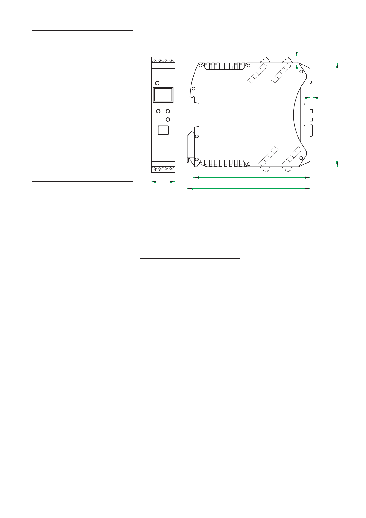
117.5 (4,63”)
99 (3,90”)
2.3
22.5
111 (4,37”)
5.5
(0,87”)
(0,08”)
(0,20”)
Klemme /
terminal
1516 17 18
5678
1234
11 12 13 14
Klemme /
terminal
Fig. 4: Dimensions CI 45

Simulation function
The built-in simulation serves to test
the settings.
Import function
Engineerings of UNIFLEX CI/CB crea-
ted by engineering tool ET/Uniflex can
be read and transformed if possible.
Software requirements:
Windows 95/98/NT/2000/XP
Configuration settings made only via
the BlueControl®software (not via the
transmitter’s front keys)
•Customer-specific linearization
•Enable forcing for inputs and
outputs
•Setting the limits for operating
hours and switching cycles
•Switch-over to 60 Hz mains
frequency
•Blocking operator functions,
Operating Levels, and password
definition
Hardware requirements:
A special PC adapter (see ‘Accesso-
ries’) is required for connecting to the
transmitter.
Updates and demo software from:
www.pma-online.de
6 UNIFLEX CI 45 - Preliminary-
Description Quantity Order no.
1Connector set with screw terminals 4 pieces 9407-998-07101
2Connector set with spring-clamp terminals 4 pieces 9407-998-07111
3Bus connector for fitting in top-hat rail 1 piece 9407-998-07121
4Plug for bus connection, connections at left,
horizontal cable entry
1 piece 9407-998-07131
5Plug for bus connection, connections at right,
vertical cable entry
1 piece 9407-998--07141
ACCESSORIES
Functionality Mini Basic Expert
parameter and configuration setting yes
download: writes an engineering to the transmitter
online-mode / visualisation SIM only
creation of user defined linearizations
configuration of extended operation level
upload: reads an engineering from the transmitter SIM only
basic diagnosis function no
saves files and engineering data
printer function
online documentation / help system
measurement correction (calibration procedure)
data acquisition and trend function SIM only
net- / multi licence
yes yes
yes yes yes
yes yes
yes yes yes
yes yes yes
yes yes
no yes
no yes yes
no yes yes
yes yes yes
yes yes yes
yes yes
no no yes
personal assistant function
BlueControl®, versions und functions:
Fig. 5: Interface parameters hidden, only
address visible
1
2
3
45
ACCESSORY PARTS

- Preliminary- UNIFLEX CI 45 7
Description Language Order no.
PC adapter for the BluePort® front
interface
9407-998-00001
USB serial adaptor (USB to RS 232) 9407-998-00081
Converter RS 232 to RS 422/485 galv. isolated ADAM-4520-D
Operating instructions for CI 45 German 9499-040-71718
Operating instructions for CI 45 English 9499-040-71711
Interface description for Modbus rail line German 9499-040-72018
Interface description for Modbus rail line English 9499-040-72011
BlueControl® Mini German/English www.pma-online.de
BlueControl® with Basic license rail line German/English 9407-999-12001
BlueControl® with Expert license rail line German/English 9407-999-12011
ADDITIONAL ACCESSORIES
CI45 1 0Universal transmitter CI 45
0
1
no plug-in connectors
2
18...30VAC/18..31VDC, mA/V/logic +1 relay 3
90..260V AC, mA/V/logic +2 relay
4
18...30VAC/18..31VDC, mA/V/logic +2 relay 5
0
1
Standard configuration 0
Configuration to order 9
Standard (CE-certified) 0
0
RS 485 / MODBUS - protocol
with screw-terminal plug-in connectors
90..260V AC, mA/V/logic +1 relay
1 universal-input, control-input
with display and BluePort®-interface
no option
0
ORDERING INFORMATION

PMA
Prozeß- und Maschinen- Automation GmbH
P.O. Box 31 02 29
D-34058 Kassel
Tel.: +49 - 561- 505 1307
Fax: +49 - 561- 505 1710
E-mail: [email protected]
Internet: http://www.pma-online.de
Your local representative
Printed in Germany - Edition 11/2004- Subject to change without notice - 9498 737 48313
- Preliminary-
Table of contents
Popular Transmitter manuals by other brands


Kramer
Kramer TA-110HD user manual

Evikon
Evikon PluraSens E2670-O2 user manual

Ramsey Electronics
Ramsey Electronics FM25A Assembly and instruction manual

Endress+Hauser
Endress+Hauser Liquisys M COM 223 operating instructions

Primex
Primex XR TIME SYNCHRONIZATION Installation & user guide

AMX
AMX TX-SK Plus Dimensional drawing


