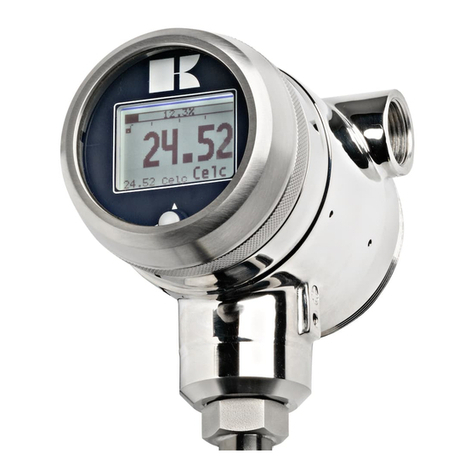
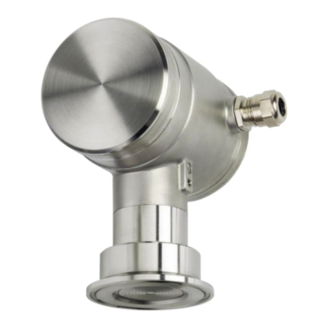
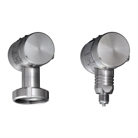
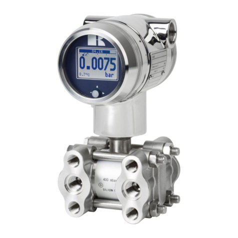
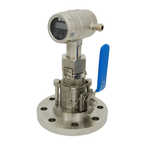
KLAY-INSTRUMENTS TT-2000 Series User manual

INSTRUCTION MANUAL SERIES TT-2000
"INTELLIGENT"
Pt-100 TEMPERATURE TRANSMITTER
Manufactured by:Nijverheidsweg 5 7991 CZ DWINGELOO
P.O. Box 13 7990 AA DWINGELOO
Tel: +31 521-591550 The Netherlands
www.klay.nl Fax: +31 521-592046 E-Mail: [email protected]

Manual Serie TT-2000 Klay Instruments B.V.
H/EN/2000-TT/09-2021/09 Page 2
CONTENTS
SECTION PAGE
1 Introduction 3
1.1 Description Series TT-2000 3
2 Dimensions 3
3 Installation transmitter 3
3.1 Welding instruction 3
3.2 Mounting position 4
3.3 Calibration 4
3.4 Wiring 4
4 Remaining 4
4.1 Digital local indicator 4
4.2 CE / EMC - Rules 5
4.3 External load 5
4.4 Traceability year of manufacturing 6
4.5 Software revision 6
5 Functions of pushbuttons 6
6 Programming points (P101 t/m P110) 7
7 Reading on display 7
8 Explanation of programming points 7
P101 Zero adjustments (4 mA) 8
P102 Span adjustment (20 mA) 8
P104 Adjustment temperature unit 8
P105 Reverse output: (20-4 mA) 8
P106 Damping adjustment 8
P107 Free adjustment (5 points) 9
P108 Configuration 9
P109 Read out on Display 9
P110 Current simulation (4-20 mA) 9
9 HART ®Protocol 9
10 Precautions and warnings 10
Attachment: EU-Declaration of Conformity

Manual Serie TT-2000 Klay Instruments B.V.
H/EN/2000-TT/09-2021/09 Page 3
1INLEIDING
The Series TT-2000 is a complete Stainless Steel temperature transmitter, based on a Pt-100 element
(1/3 DIN class B). The range of standard elements can be set between -50 and 200 °C. Other ranges
are available on request. The Pt-100 element is mounted in a stainless steel plug (sensor position 9).
To obtain an accurate and fast measurement, the diameter of the insert part has to be chosen as small
as possible. The resistance change of the Pt-100 element due to temperature change is converted into
a proportional 4-20 mA signal (2-wire).
A great diversity in designs and process connections can be made including milk couplings (DN25, 40
and 50), Tri-clamp (1, 1 ½ "or 2") and hygienic weld-on-nipples like ¾ "BSP nut (diameter 28 mm).
Associated immersion tubes (Thermowell) fully welded and manufactured from execution (bar stock)
are available in various designs and materials (on request).
2DIMENSIONS
PARTS DESRIPTION MATERIAL
1. Cover AISI 304
2. Pushbutton + Display
3. Cover with venting AISI 304
4. Venting PA
5. PG Cable gland
6. O-Ring (2 pcs) EPDM
7. Electronics housing AISI 304
8. Neck tube AISI 304
9. Process connection AISI 304
10. Insertion part AISI 316
Sensor tip
Specify Length Land Diameter D
3 INSTALLING WELD-ON NIPPLE
A skilled machinist or welder should perform installation of the weld-on nipple.
Weld Argon, MIG or TIG with the smallest welding pin.
1. Cut a hole in the process vessel/pipe to accept the weld-on nipple.
2. Remove the weld-on nipple from the transmitter.
3. Position a welding mandrel into the weld-on nipple and screw it down.
WARNING
Never weld the entire nipple at once.
Excessive heat input will deform the weld-on-nipple.
Cool each and every well after each welding cycle.

Manual Serie TT-2000 Klay Instruments B.V.
H/EN/2000-TT/09-2021/09 Page 4
4. Position the weld-on nipple in the vessel hole and tack six places.
5. The weld sequence is shown in the figure above. Weld the weld-on nipple in place using
0,03 to 0,045 in. (0,762 to 1,143 mm) stainless rod as filler material in the beveled area.
Adjust amperage for penetration pliers (1/8").
6. Remove mandrel after the welding operation.
3.2 MOUNTING POSITION
When the transmitter is mounted horizontally, the cable gland must be pointed downwards.
3.3 CALIBRATION
All transmitters are fully calibrated at the factory, to the conditions stipulated in users order. When the
customer has not requested calibration, the transmitter will be calibrated 0-100 °C.
3.4 WIRING
Under the cover (3) you will find the terminal board. Under the other cover (1) are the buttons for the
zero and span adjustment.
External loads must be placed in the negative leg of
the 2-wire loop.
The figure left shows the wiring connection of the
transmitter. The 2-wires must be connected to 3 (-) and
4 (+) of the terminal board.
The signal wiring must be shielded and twisted pairs
yield best results. Do NOT run signal wiring in open
trays with power wiring, or near heavy electrical
equipment (Frequency controller or heavy pumps).
Shielding must always be connected at the side of the
power supply.
In case the mounting position is already connected to
earth (by tank or pipe line) do NOT connect the
instrument to earth. Please ensure that the instrument
is not connected to earth twice to prevent the
occurrence of an 'earth loop'. In applications with
synthetic mounting positions the case grounding
terminal (internal or external) must be connected to
earth.
Care must be taken to assure that the polarity of the power supply is correct, a reversal of wiring
polarity will not damage the transmitter, but it will not function until the wiring is connected correctly.
4. REMAINING
4.1 DIGITAL LOCAL INDICATOR
All temperature transmitters from the series TT-2000 are standard equipped with a digital display. In the
standard version closed covers are used. The push buttons and the display are behind the cover (3).
As an option an transparent cover can be delivered for the application as a local display in the process
(Option: "I" extra price). The full-scale point may be set to any value between 0000 and 9999 (4 digit)

TERMINAL CONNECTION

Manual Serie TT-2000 Klay Instruments B.V.
H/EN/2000-TT/09-2021/09 Page 5
4.2 CE / EMC Rules
All transmitters are fitted with RFI filters, which provide optimum, trouble-free operation. Our products
are in conformity with EMC-Directive 2014/30/EU based on test results using harmonized standards.
4.3 EXTERNE RESISTOR
The minimum power supply is based on the total circuit
resistance. The maximum permissible load(Rimax.) in case of 24
Vdc is 600 Ω (Ohm).
By increasing the power supply, the external load can be
increased to 1200 Ohm / 36 Vdc. (see figure left).
Rimax. = Supply - 12 V (minimal supply)
20 mA
With a loop resistance of 250 Ω a power supply of at least 17 Vdc must be used.
0
200
400
600
800
1000
1200
1400
12 24 36
Ohm
Vdc

Manual Serie TT-2000 Klay Instruments B.V.
H/EN/2000-TT/09-2021/09 Page 6
4.4 TRACEBILITY YEAR OF MANUFACTURING
The year of manufacturing of the transmitter can be traced as follows: take the first two numbers from
the serial number that is engraved in the transmitter and add 1970 to it.
For example: if the 3902123. The year of manufacturing is 1970 + 39 = 2009.
4.5 SOFTWARE REVISIES
Due to the improvements on the Series TT-2000, there are several software versions (revisions). For
this reason it is possible the temperature transmitter you are working with does not support some
options, which are discussed in this manual. Ask Klay Instruments BV.
5EXPLANATION PUSHBUTTONS
The Series TT-2000 can be programmed easily by use of
the 3 front panel pushbuttons (See picture right).
On het display several engineering units can be
used: °C, °F, mA and %
The functions of the three pushbuttons will be explained
below.
This button has 2 functions:
It can be directly used for adjusting the
zero (zero / 4mA), with or without a test pressure. When the zero (4 mA) must be
adjusted at 0 °C, the button must be held until the word "ZERO" appears on the display.
The transmitter is now set to 4 mA.
Test temperature should be 0 °C.
Also, this button must be used for stepping down in the programming menu
or to decrease a value (-).
This button has 2 functions:
It can be directly used for adjusting the span (20 mA), when using a test pressure (air).
When a test pressure (50 °C) is supplied to the transmitter, the button must be held until the
word "SPAN" appears on the display. The transmitter is adjusted at 0 - 50 °C.
Also, this button must be used for stepping up in the programming or to
increase a value (+).
This button has 2 functions:
It is used to adjust the 11 Programming Points (P101 to P111). Push it once and P100 is
displayed, use the [] (SPAN) to step to P101 etc.
This button must also be used for confirming the adjustments (enter).

Manual Serie TT-2000 Klay Instruments B.V.
H/EN/2000-TT/09-2021/09 Page 7
6. PROGRAMMING POINTS (P101 –P110)
The following points can be adjusted by means
of the three push buttons. For an explanation
of these points see the next pages of this
manual.
To change one of these points you have to
push on [PROG] until "100" appears on the
display. To go to from a lower program (P101)
to a higher one (P102), push on button []
(SPAN).
To confirm the adjustments you always have to
press on [PROG].
*) Standard adjustments ex works.
Programming points:
P101
Zero adjustment (4 mA)
P102
Span adjustment (20 mA)
P104
Adjustment temperature unit on display
(See conversion table)
P105
4 –20 mA (*)
20 –4 mA
P106
Damping adjustment (0 till 25 s.)
P107
Free adjusment (5 points)
P108
Configuration
P109
Readout display:
0 = Current (4 - 20 mA)
1 = Temperature unit (conversietabel)
2 = Percentage
3 = Ambient temperature
P110
Simulation of current
7. READING ON THE DISPLAY
On the standard built-in display several values can be shown.
During programming of the temperature transmitter
the display shows all the information that is needed.
When the transmitter is in the process the display gives
all the information of the process temperature.
On the display the following units can be shown: mA, percentages or in temperature (see also P108).
The standard temperature TT-2000 transmitter is supplied with two "closed" covers shielding the buttons and the
display. As an option an "open" cover (IP 65) can be fitted. The display can then be used as a local process display.
(Option: "I" extra price).
8. UITLEG PROGRAMMEERPUNTEN P101 t/m P110
NULPUNTS INSTELLING (ZERO, 4 mA) ZONDER TESTTEMPERATUUR
The TT-2000 as standard is adjusted at 0 °C to 4.00 mA.
It is also possible to adjust a zero-suppression or elevation..
For example: zero elevation of +10 °C.
1. Push at [PROG] until "100" is shown on the display.
2. Push once at [] / SPAN till "101".
3. Confirm this by pushing [PROG].
4. Now the display will show 0.00 and zero. Push at [] till 10.00 is on the display.
5. Confirm with [PROG].
6. The transmitter will automatically return to the set reading.
At a temperature of +10°C is 4.00 mA output.
Note: the measured value is not 4.00 mA at room temperature.
i
P101

Manual Serie TT-2000 Klay Instruments B.V.
H/EN/2000-TT/09-2021/09 Page 8
SPAN ADJUSTMENT (20 mA) WITHOUT TEST TEMPERATURE
Before adjusting the span take care the right temperature unit is selected.
(See also P104 and P108).
Example: Range 0 - 100 °C
1. Push [PROG] till "100" is shown on the display.
2. Push twice at [] / SPAN until "102" is on the display.
3. Confirm this by pushing [PROG].
4. Push [SPAN] (+) or [ZERO] (-) to select the measuring range that is required.
5. Confirm by pushing [PROG].
The TT-2000 is adjusted now.
P102 is the adjustment of the total span. When a compound range must be
adjusted (for example -30 till +70 °C), a span of 100 °C must be programmed. At
P101 (ZERO,4 mA), -30 °C must be adjusted. Now the transmitter is adjusted at:
- 30 °C = 4 mA and +70 °C = 20 mA.
ADJUSTMENT TEMPERATURE UNIT ON DISPLAY
Several engineering units can be shown on the display by using a conversion factor.
(See conversion table below). As standard the read out from TT-2000 is set to ‘Degr ‘
(degrees C). To change this setting, the following must be set:
1. Push at [PROG] till "100" is shown on the display.
2. Push 4 times at [], go to [P104].
3. Push at [PROG] to confirm this.
4. Push at [] / [SPAN] (+) and set it to Fahr (See conversion table below).
5. Push [PROG] to confirm.
The transmitter will now read out in ‘Fahr’
For correct conversion between both temperature scales the following conversion
calculation must be used.
Celsius naar Fahrenheit
°C = (°F −32) × 5⁄9
Fahrenheit naar Celsius
°F = °C × 9⁄5+ 32
When the value of the highest range is larger than 9999, "NA" will appear in the display
(Not Applicable). Another unit must be chosen.
REVERSE OUTPUT (20 - 4 mA or 4-20 mA)
The transmitter as standard is adjusted to 4-20 mA.
Push on [PROG] and go to P105.
Push once at [] to change the output to 20-4 mA (Reverse output).
Push at [PROG] to confirm this.
ADJUSTMENT DAMPING (0 till 25 s.)
In P106 an electronic damping can be adjusted between 0 and 25 seconds.
This can be done with the push buttons [] (up) and [] (down).
Always confirm by pushing once at [PROG].
FREE ADJUSTMENT (5 POINTS)
1. Push on [PROG] and go to P107.
2. Push 7 times at []/[SPAN] go to [P107].
3. Push at [PROG] to confirm this.
4. Adjust the desired points and push at [PROG] to confirm this.
P102
P104
P105
P106
P107

Manual Serie TT-2000 Klay Instruments B.V.
H/EN/2000-TT/09-2021/09 Page 9
CONFIGURATION
1. Push on [PROG] and go to P108.
2. Push 8 times at []/[SPAN] go to [P108].
3. Push at [PROG] to confirm this.
4. Adjust the configuration and push at [PROG] to confirm this.
READ OUT ON DISPLAY
0 = Current (4 - 20 mA)
1 = Temperature unit (See conversion table)
2 = Percentage (0 - 100%)
3 = Ambient temperature (Depending on conversion table)
As standard the transmitter is delivered with read out in units(1).
To change this, follow the next steps:
1. Push [PROG] until "100" is shown on the display.
2. Push 9 times at [] / SPAN till "108" appears on the display.
3. Confirm with [PROG].
4. Push once at [].
5. Push [PROG] to confirm this.
The transmitter will now read (°C or °F)
Also the readout can be 0 - 100%. In this case select P108, option 2
SIMULATION OF CURRENT (4-20 mA)
The transmitter can be used as a simulator of a current between 4 - 20 mA.
9 HART ®Protocol
The Series TT-2000 can be used with the HART®5 protocol. To read the measurements, the generic
HART commands can be used.
When using HART ®, the total resistance of the circuit must be at least 250 Ω. This is necessary
for proper communication. In this case, the connected power supply must be at least 17 Vdc.
P108
P109
P110

Manual Serie TT-2000 Klay Instruments B.V.
H/EN/2000-TT/09-2021/09 Page 10
10. PRECAUTIONS and WARNINGS
Check if the specifications of the transmitter meet the needs of the process conditions
Never weld the entire weldon nipple in one session.
Once the wiring has been inserted and connected, make sure that the PG9 cable gland is hermetically
sealed (screwed) so that no moisture can penetrate the cable gland into the electronic housing.
Avoid high pressure water-jets pointed at the venting.
The covers must be fully engaged, so that moisture cannot ingress into the electronic housing.
The covers must only be capable of being released or removed with the aid of a tool.
The warranty is 1 year from delivery date.
Klay Instruments B.V. does not accept liability for consequential damage of any kind due to use or
misuse of the Series TT-2000. Warranty will be given, to be decided by the manufacturer. Transmitter
must be shipped prepaid to the factory on manufacturers authorization.
Klay Instruments B.V. reserves the right to change its specifications at any time, without notice. Klay
Instruments B.V. is not an expert in the customer’s process (technical field) and therefore does not
warrant the suitability of its product for the application selected by the customer.
Manufactured by: Nijverheidsweg 5 7991 CZ DWINGELOO
P.O. Box 13 7990 AA DWINGELOO
Tel: +31 521-591550 The Netherlands
www.klay.nl Fax: +31 521-592046 E-Mail: [email protected]
This manual suits for next models
1
Table of contents
Other KLAY-INSTRUMENTS Transmitter manuals

KLAY-INSTRUMENTS
KLAY-INSTRUMENTS 8000-SAN Series User manual

KLAY-INSTRUMENTS
KLAY-INSTRUMENTS TT4000 Series User manual

KLAY-INSTRUMENTS
KLAY-INSTRUMENTS PROFIBUS PA 4000 Series User manual

KLAY-INSTRUMENTS
KLAY-INSTRUMENTS 2000-SAN Series User guide

KLAY-INSTRUMENTS
KLAY-INSTRUMENTS DP-4000 Series User manual

KLAY-INSTRUMENTS
KLAY-INSTRUMENTS 8000 Series User guide

KLAY-INSTRUMENTS
KLAY-INSTRUMENTS 2000-SAN Series User manual

KLAY-INSTRUMENTS
KLAY-INSTRUMENTS PERAMIC User manual

KLAY-INSTRUMENTS
KLAY-INSTRUMENTS 2000-VALVE-RANGE Series User manual

KLAY-INSTRUMENTS
KLAY-INSTRUMENTS 2000-SAN Series User manual