ASSEMBLY INSTRUCTIONS
These instructions should be read carefully and left with the user of the product for future reference.
1. Secure the Brand Plate (1) to the front guard (2) with the screws provided.
2. Take the guard lock nut (6) o from the motor shaft and place the rear guard (7) on the front of the
motor housing.
3. Line up the lugs on the front of the motor housing with the holes in the rear guard and screw on the
plastic nut (6) tightly to attach rear guard (7).
4. Place the fan blade (5) on the motor shaft and secure it by tightening the spinner (4) in an anti-
clockwise direction.
5. Fit the front guard (2) onto the rear guard (7) and close the clips (3), then secure the grill with the
screw (19).
Stand Fan
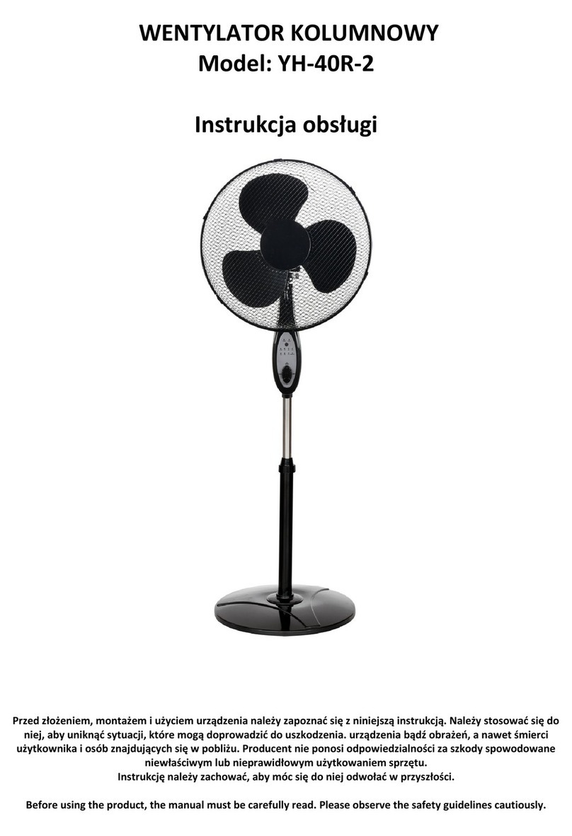
1. Insert the base tube (16) into the Base Top (17).
2. Then tighten with the locking bolt (18) to secure the base top (17).
3. Insert metal nut (23) into groove on base of control unit (13) (see diagram 1)
4. Place the switch box (13) on the pole (15) and fasten with the control unit knob (14).
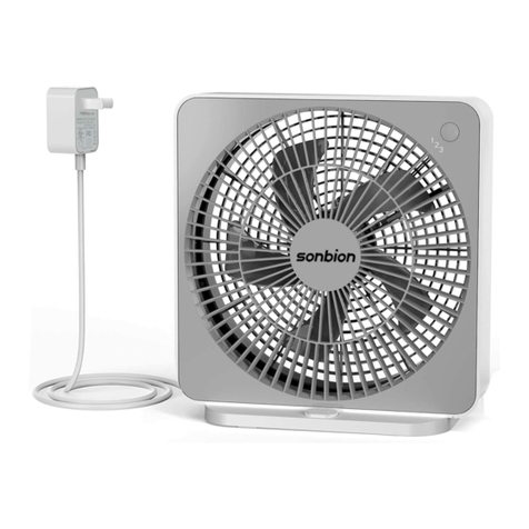
Desk Fan
1. Insert metal nut (23) into groove on base of control unit (13) (see diagram 1)
2. Place the control unit (13) directly on to the Desk Base (20) and fasten with the control unit knob
(14) to secure.
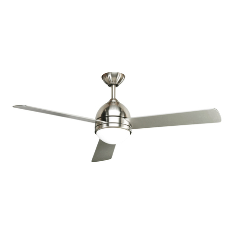
Wall Fan
1. Check the wall before installing for suitability. Mounting
hardware is not supplied and must be suitable for the
structure the fan is being mounted on.
2. Locate and mark the position on the wall where the fan will
be mounted, using the wall bracket (21) as a template. The fan
is to be installed so that the blades are more than 2.3m above
the oor. Do not mount the wall bracket yet.
3. Insert your own plugs and screws into the wall leaving
approx. 5/8” (1.6cm) of the screw exposed.
4. Insert metal nut (23) into groove on base of control unit (13)
(see diagram 1)
5. Mount the control unit (13) onto the wall bracket (21) and
insert and tighten screw (24).
6. Line up the screws in the wall with the mounting holes in the
bracket, and then move the bracket downwards to secure.
The screws should be tightened to provide a rm t.
Diagram 1 (Base of Control Unit)
HOW TO OPERATE
Put the fan on a level even stable surface and plug the power cord into the mains socket, making sure
the speed control is in the OFF position.
Using the Remote Control open the cover located at the bottom of the remote control and insert the
batteries.
OFF: Turns the fan o.
ON/SPEED: Turns the fan on and also sets the speed.
TIMER: Allows the timer to be set to: 1, 2, 4 or 7.5hrs.
OSCILLATION: The oscillation mechanism can be activated by pushing the oscillating pin (10) down.
Pulling the pin back up will stop the fan from oscillating.
3
23 13


