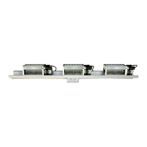
TECSYSTEM UNIVERSAL BAR DIAM.80 User manual

2
UNIVERSAL BAR DIAM.80
TABLE OF CONTENTS
INTRODUCTION
First of all we wish to thank you for choosing to use a TECSYSTEM product and recommend you read this instruction
manual carefully: You will understand the use of the bar and therefore be able to take advantage of all its functions.
ATTENTION! THIS MANUAL IS VALID AND COMPLETE FOR THE PRODUCT UNIVERSAL BAR DIAM.80
PAGE
1)
SAFETY REGULATIONS
…………………………
3
2)
BAR TECHNICAL SPECIFICATIONS
…………………………
4
3)
FAN PARAMETERS
…………………………
—
4)
UNIVERSAL BAR PRESENTATION
…………………………
5
5)
BAR AND FANS ASSEMBLY
…………………………
6
•NOTES ON ASSEMBLY
…………………………
8
6)
ELECTRICAL CONNECTIONS
…………………………
9
•POWER SUPPLY
…………………………
10
•ENVIRONMENTAL CONDITIONS OF USE
…………………………
—
•MAINTENANCE
…………………………
—
7)
FAN DIMENSIONS
…………………………
11
8)
BAR DIMENSIONS
…………………………
12
9)
WARRANTY REGULATIONS
…………………………
13
10)
EQUIPMENT DISPOSAL
…………………………
—
11)
USEFUL CONTACTS
…………………………
—

3
UNIVERSAL BAR DIAM.80
FANS SAFETY REGULATIONS
ATTENTION:
Read the manual carefully before starting to use the fans. Keep the instructions for future reference.
Do not touch/disassemble the bar or the fans while they are in operation: RISK OF INJURY.
The product must be installed in a place with access limited to qualified personnel only. Any work on the equipment
must be entrusted to a qualified engineer.
Do not touch the motor or the power cables. Contact with a voltage of 120/230 Vac can be fatal. To reduce
the risk of electric shock, do not dismantle or modify the fan motor for any reason.
Before connecting the system to the power supply, make sure that all the connections are correct. Always
disconnect the fan from the power supply before performing any type of maintenance.
Never touch the motor, danger of burns: RISK OF INJURY.
POWER SUPPLY
Before using it, always make sure the power cable is not damaged, knotted or pinched.
Do not tamper with the power cable. Never disconnect the unit by pulling the cable and avoid touching the pins. Do not
carry out any operations of connecting/disconnecting with wet hands. To disconnect the system, do not use objects
such as levers. Immediately disconnect the power supply if it is evident that the system is giving off a smell of burning or
smoke and contact the Tecsystem technical assistance.
LIQUIDS
Do not expose the product to dripping or splashing liquids. Do not place in places with humidity over 90% and never
touch with wet or damp hands.
CLEANING
Before cleaning the fan, always disconnect the power cord. To avoid malfunctions only use compressed air to remove
dust and dirt. Do not use lubricants or greases of any kind.
OBJECTS
Never insert objects into the air inlet or outlet If this happens disconnect the fan and contact a technician.
USE RESERVED TO QUALIFIED PERSONNEL
The purchased product is a sophisticated electro-mechanical device that must never be used by non-qualified
personnel. Any work must be carried out by a specialist engineer.
ACCESSORIES
Do not use non-original accessories or spare parts as this could cause damage to the fan and endanger the user. In
case of faults, contact technical assistance.
LOCATION
Install the fan indoors in a place protected from water splashes and from the sun’s rays. Do not place near heat sources
exceeding the parameters stated in this manual. Place horizontally and on stable surfaces. The product must be
installed in a place with access limited to qualified personnel only.
REPAIRS
Do not repair or modify the fan yourself. For any fault, always use qualified personnel. Opening or tampering with the
fan automatically invalidates the warranty.
PRODUCTION
The date and the production batch of the product are shown on a label placed on the fan. Removal of the label
automatically invalidates the warranty.
TECHNICAL OR REPORTING INFORMATION
Mail: ufficiotecnico@tecsystem.it - tel.:+39 024581861

4
UNIVERSAL BAR DIAM.80
TECHNICAL SPECIFICATIONS TG80/2 230Vac 50Hz
MODEL
TG180
TG360
TG500
POWER SUPPLY
230Vac –50Hz
CURRENT
0.34A
0.45A
0.54A
POWER
75W
95W
120W
TECHNICAL SPECIFICATIONS TG80/2 230Vac 60Hz
MODEL
TG180
TG360
TG500
POWER SUPPLY
230Vac –60Hz
CURRENT
0.57A
0.74A
0.85A
POWER
114W
160W
187W
TECHNICAL SPECIFICATIONS 120Vac 60Hz (UL)
MODEL
TG180
TG360
TG500
POWER SUPPLY
120Vac –60Hz
CURRENT
1.24A
1.65A
1.88A
POWER
132W
188W
210W
TECHNICAL SPECIFICATIONS
MODEL
1200
1800
3600
BAR LENGTH
1400mm
1800mm
2300mm
NUMBER OF FANS PER BAR
3
3
3
MODEL OF FANS
TG180
TG360
TG500
FAN LENGTH
180mm
360mm
500mm
FAN DIAMETER
80mm
80mm
80mm
FLOW RATE
1380 m3/h
2400 m3/h
3000 m3/h
AVAILABLE POWER SUPPLIES (*)
(230Vac –50Hz) —- (230Vac 60Hz) —- (120Vac-60Hz)
(*) Note: the indicated power supplies are available upon customer request or depending on the model purchased.

5
UNIVERSAL BAR DIAM.80
UNIVERSAL BAR PRESENTATION
The new Tecsystem universal bar has been designed to simplify the positioning of the fans immediately under the columns
of the resin transformers and also allows better adaptability to the dimensions of the transformer from 1250KVA to over
2500KVA.
The aluminium construction has allowed us to obtain a very light bar but that is, at the same time, robust and resistant even
in the most extreme environments.
1MN0204 REV.0
The bar consists of:
•two side profiles 645mm
•a central profile length 1400mm
The two side profiles have been designed to slide inside the central profile in order to guarantee an extension from
1400mm to 2300mm.The same bar can be used to compose the bars: 1200-1800-3600, installing on it the models of fans:
TG180 - TG360 - TG500 depending on the bar model to be assembled.
1MN0205 REV.0
The bottom of the bar is used to house the power cables of the fans. The wiring of the fans has been designed to satisfy
all sizes of 1200-1800-3600 bars.
The central profile also has an integrated 35mm DIN RAIL, useful for the attachment of any optional connection
terminals.

6
UNIVERSAL BAR DIAM.80
BAR AND FANS ASSEMBLY
1MN0233 REV.0
1MN0210 REV.0
Position the closed bars on the sides of the transformer (BAR1-BAR2).
Arrange the bar on the transformer carriage and centre the positioning of the bar using the central column of the
transformer as a reference.
Remove the bar locking screws and detach the cables, bar initial position 1200, and if necessary slide the side profiles
up to the desired dimension 1800-3600.The M4 locking screws are used to fasten the bar at the desired length 1200-
1800-3600 and must be inserted in the appropriate 4mm diameter holes.
Fasten the bar on the transformer carriage using the dedicated fixing slots, suggested M8 bolts plus washer.
NOTE: insert the bolts, locking both profiles: central and lateral on the transformer carriage.
1MN0258 REV.0
SIDE BAR VIEW

7
UNIVERSAL BAR DIAM.80
Use the dedicated slots on both profiles and the self-drilling screws, supplied, to lock the fans in the desired position.
Place the fans on the bar and centre each individual fan with the U-V-W reference column.
1MN0207 REV.0
U
V
W
1MN0206/8 REV.0
Appropriately position the wiring for the fans, M1-M2-M3. Place any excess wiring back into its casing reclamping the
cables. Connect the power cord to each installed fan.
M3
1MN0234 REV.0
M1
M2

8
UNIVERSAL BAR DIAM.80
Use the fan flappers to correctly direct the air inside the transformer columns.
1MN0209 REV.0
ATTENTION: always maintain the safety distance from the windings, indicated by the transformer
manufacturer.
1MN0208 REV.0
1MN0232 REV.0
Fan fixing holes
Air flow direction inside the transformer
NOTES ON ASSEMBLY
Fasten the fans on the bar using the dedicated holes on the back; do not modify the fixing holes of the fan.
When handling the fans, avoid deforming the impeller fins. Never modify the positioning of the motor.
If the fan/bar is mounted on a transformer, the working position of the fan must respect the safety distance indicated in the
manual of the transformer on which the fan is being installed.
The fan must be positioned horizontally; always make sure, using a spirit level, that the fan is positioned correctly.
The maximum permitted vibration level is 60Hz.

9
UNIVERSAL BAR DIAM.80
ELECTRICAL CONNECTIONS
1)
Bar earth connection screw
3)
Power plug connector
2)
Cap
4)
Cap
ATTENTION: the 120VAc 60Hz fans have a different wiring therefore consult the quick guide manual available
inside the package of the purchased product.
Strip the outer sheath of the multipolar cable (L-EARTH-N)
to a length of 55mm. Strip the three conductors 9mm.
Keep the earth conductor with an increased length of
8mm.
Using a 2.5mm slotted screwdriver, press the internal
spring of the connector. Insert the stripped conductor MAX
4mm, preferably with a dedicated ferrule, inside the
reference terminal with the respective marking L, EARTH
or N.
Terminate the connection by inserting the other L-EARTH-
N conductors.
Apply the protective casing supplied and tighten the
locking screw.
1
2
1MN0236 REV.0
1MN0209 REV.0
4
1MN0240 REV.0
3
BAR CONNECTOR
Assemble the socket connector + casing following what is reported below.
1MN0238 REV.0
1MN0237 REV.0
1MN0239 REV.0
BAR WIRING
The bar has a recessed plug connector for powering of the fans:M1-M2-M3 (*). By using the socket connector + casing, it
will be possible to connect the fans electrically, following the assembly procedure.
(*) the wiring with dedicated connector for the single fan is available on request.

10
UNIVERSAL BAR DIAM.80
Should it be necessary, modify the wiring or disconnect the connectors.
Using a 2.5mm slotted screwdriver, press the PUSH spring
under the connector. Move the socket connector slightly left
and right and pull.
Using a 2.5mm slotted screwdriver, press the internal
spring of the connector. Pull out the conductor.
Insert the socket connector + assembled casing (1) inside the plug connector (2) arranged on the bar.
1
2
POWER SUPPLY
Before connecting the ventilation bar to the power supply, always check that: the voltage and frequency parameters shown
on the fan label correspond to the values available on the system.
ENVIRONMENTAL CONDITIONS OF USE
Absence of fine dusts.
Absence of flammable or corrosive gases.
Relative humidity:90% non-condensing (for short periods).
N.B.: maximum temperature as prescribed by the IEC 60076-11 standard.
Installation in a marine environment is not recommended, unless after specific treatment of the metal parts.
NOTE: failure to comply with the assembly notes and possible use in extreme environmental conditions such as:
lengthy periods of standstill, high humidity, high temperatures, excessive dustiness and excessive vibrations, can
anticipate deterioration of the mechanical parts of the fans.
MAINTENANCE
In order to maintain the efficiency of the fans, clean them periodically (every 6 months) using only compressed air. Do not
use lubricants or greases of any kind.
Any prolonged standstill of the fan could cause malfunctions. Installation of the fans combined with the Tecsystem
thermometric control units avoids any prolonged shutdowns. By enabling the HFN function present in the Tecsystem
control units, it is possible to program fan activation cycles from 1 to 200 hours, recommended setting every 24 hours (for
further information on the HFN function, check the manual of the control unit purchased).
NOTE: Periodic maintenance and activation of the HFN will allow you to extend the efficiency of the fans.
Maintenance operations on the fans must be scheduled according to the environmental conditions in which they
operate.
PUSH
1MN0241 REV.0
1MN0241 REV.0
1MN0242 REV.0

11
UNIVERSAL BAR DIAM.80
FAN DIMENSIONS
TG180 1VN0006
TG500 1VN0016
TG360 1VN0010
1MN0230 REV.0
1MN0229 REV.0
1MN0231 REV.0

12
UNIVERSAL BAR DIAM.80
NOTE: dimensional tolerance of bar drawings ± 10mm
1MN0243 REV.0
BAR DIMENSIONS
1MN0235 REV.0
1MN0244 REV.0
BAR 1800
BAR 3600
BAR 1200

13
UNIVERSAL BAR DIAM.80
The European directive 2012/19/EU (WEEE) has been approved to reduce the waste of electrical and electronic appliances
and to encourage the recycling and reuse of materials and components of these appliances, thereby reducing the disposal
of harmful residues and compounds originating from electrical and electronic material.
All the electrical and electronic equipment supplied after 13 August 2005 is marked with this symbol, pursuant to
European directive 2012/19/EU on electrical and electronic waste (WEEE). Any electrical or electronic equipment
marked with this symbol must be disposed of separately from normal domestic waste.
Returning of used electrical appliances: contact TECSYSTEM or the TECSYSTEM agent to receive information on correct
disposal of the appliances.
TECSYSTEM is aware of the impact its products have on the environment and asks its customers active support in the
correct and environmentally-friendly disposal of its devices.
EQUIPMENT DISPOSAL
The purchased Product is covered by the manufacturer's or seller's warranty under the terms and conditions indicated in the
"Tecsystem s.r.l. General Sales Conditions", which can be consulted on the website www.tecsystem.it and/or in the
stipulated purchase contract.
The warranty is considered valid only when the product is damaged by causes attributable to TECSYSTEM srl, such as
manufacturing or components defects.
The warranty is invalid if the Product proves to have been tampered with/modified or incorrectly connected and causing
voltages outside the set limits and does not comply with the technical data for use and assembly, as described in this
instruction manual.
The warranty is always ex Corsico as stated in the "General Conditions of Sale".
WARRANTY REGULATIONS
USEFUL CONTACTS
This manual suits for next models
3
Table of contents
Other TECSYSTEM Fan manuals
Popular Fan manuals by other brands

Hunter
Hunter Ridgefield 51107 installation manual
Savoy House
Savoy House 52-CDC-5RV-13 owner's manual
Taurus Alpatec
Taurus Alpatec Babel manual
Monte Carlo Fan Company
Monte Carlo Fan Company 5AB52XX Series Owner's guide and installation manual

EIPL
EIPL 10289MG-GB user manual

Melchioni
Melchioni MF 2412TRIO user manual


