Premium LID Q15P User manual

Page 1 of 12
Q15P
Q15P
Mitsubishi MQ Triton Dual Cab
Page 2 of 12
Q15P
• Pen / Marker • Die Grinder & multi tool • Soapy water solution
• Centre Punch • Masking Tape • Allen Key set (Metric)
• Drill & Drill bits • Scissors & Knife
• Phillips head screwdriver • Ruler
• Caulking Gun • Spanner & Socket
• Silicon - Non Acetic • Tape measure
• Read Instructions fully before commencing installation.
• Clean Tonneau Cover with a mild detergent and water solution
• Do not use abrasive cleaners or solvents
• Refer to manufactures instructions applicable to power drill.
• Protect Tub floor against scratches during installation process.
Check contents of kit before commencing fitment and report any discrepancies
Fitting Instructions Part Number Q15P
Mitsubishi MQ Triton Dual Cab 2015+
To suit Sports Bars
If lubrication of the locks or hinges is required use only Graphite Powder. DO NOT use any other
lubricants or oils.
• Do not stand/sit or rest heavy objects on Tonneau Cover
• Humans or animals are not to be under the closed Tonneau at any given time
• Securely lock tonneau Cover before operating vehicle
• Tonneau Cover is not dust or water tight
• Do not carry open volatile chemicals with Tonneau Cover installed
• If contact with volatile chemicals occur, clean Tonneau with mild detergent and water solution
Tools Required
Maintenance
Care Instructions
IMPORTANT
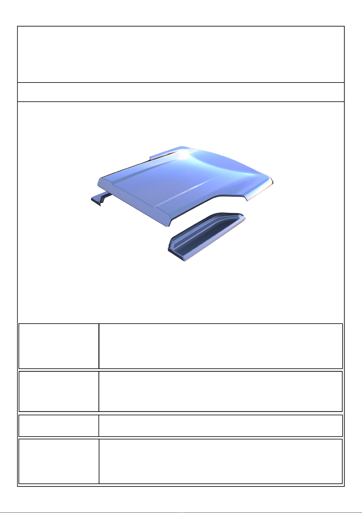
*Image example shown only

Page 3 of 12
Q15P
Installation Steps Flow Chart
START
SPORTS BAR REMOVAL
TUB PREP FOR LID INSTALL
LID INSTALL AND ADJUSTMENT
FINISH
Page 4 of 12
Q15P
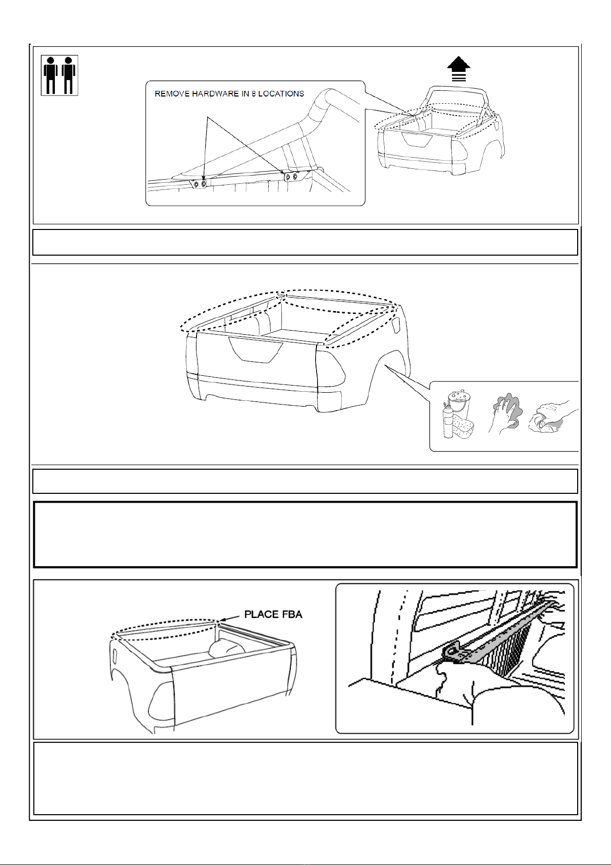
Remove the Sports Bars from the vehicle & retain the hardware for re-installation. NOTE: Two people are required.
Thoroughly clean installation areas.
Important:
Instructions are for Utes with an UNDER-RAIL tubliner. If you have an OVER-RAIL tubliner you must trim the
top off.
The Front Bar Assembly (FBA)
The FBA will already have the hinges fitted to it. Align the bar along front of tray, ensuring ends of bar are flush with
sides of tray. Remove white paper tape from rubber seal and attach the FBA using self-drilling screws (supplied)
through holes pre-drilled in bar. Apply clear or black silicone to any gaps and between the FBA and the vehicle to pre-
vent water entry.

Page 5 of 12
Q15P
Gas Struts:
Measure from the front rail inside of tub, measure along top edge of tray 780 mm (windscreen end) then down
20 mm and mark the screws position for the gas strut bracket. Position the gas strut bracket accordingly,
mark two mounting holes and centre. Refer to Fig. 1 and Fig. 2
780 mm
Fig.1 - Gas strut bracket location
20 mm
Fig.2 - Gas strut bracket location
Using a 2 mm diameter drill bit set to 5 mm drill stop. Drill two pilot holes. Attach small gas strut bracket using self
drilling screws provided. Repeat process on other side of tray. Refer to Fig. 2 and Fig.3
Fig.3 - Gas strut bracket fitment
Attach small shaft end of gas strut onto gas strut brackets, by clicking them in place.
Refer to Fig.4 with regard to gas strut orientation.
Fig.4 - Gas strut orientation
Page 6 of 12
Q15P
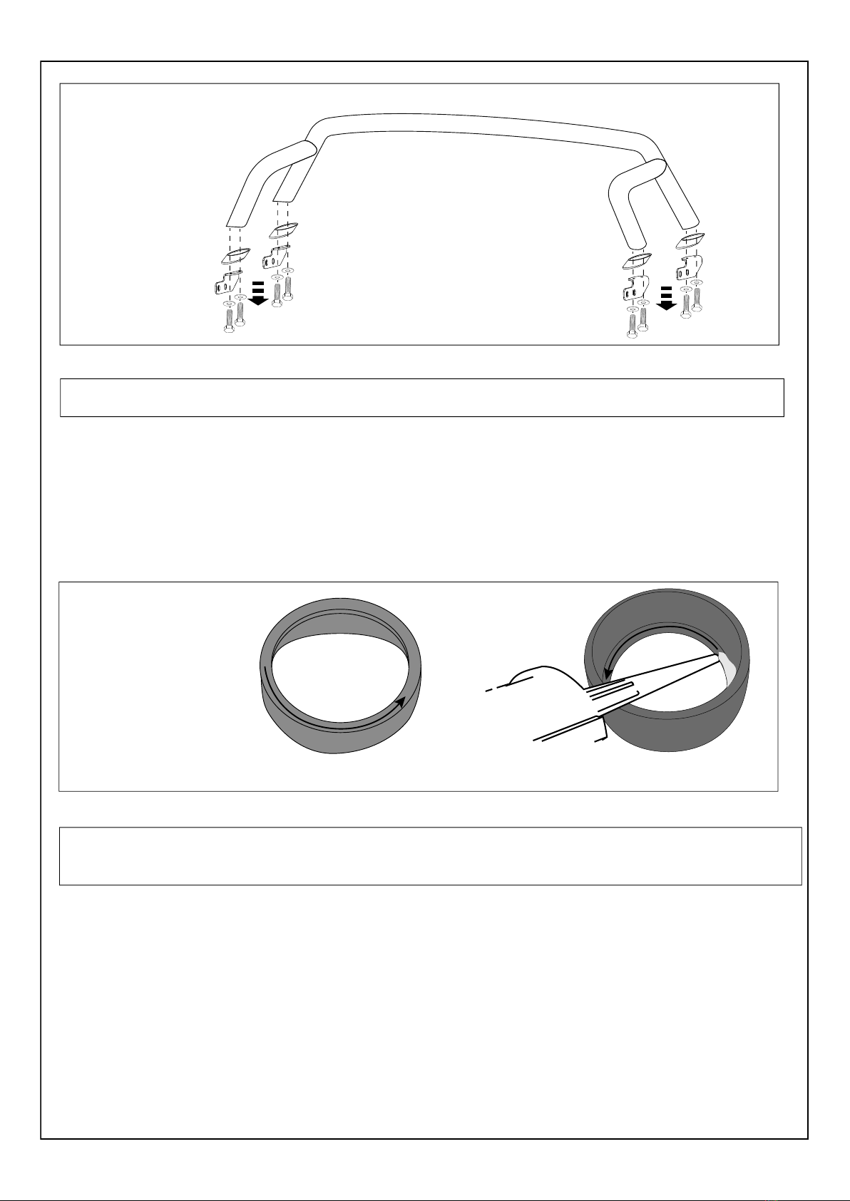
Ensure the inside of the foot caps is clean. Apply a bead of non acetic silicon (not supplied) around the inside
surface of the foot cups. Re-attach foot cups to the sports bar feet to ensure silicon seals foot cups. Ensure silicon
does not protrude above foot cups.
Remove the front and rear brackets and foot cups from the sports bar. Retain all the hardware. Flip the sports bar
over and place on a piece of cardboard to avoid damage.

Page 7 of 12
Q15P
Secure the infill panel against the sports bar feet, using the supplied and retained bolts and large washers. Do not
tighten fully in order to allow infill panel alignment on the tub.
Two people are required for this step. Carefully position the sports bar assembly on the vehicle. Re-attach legs of
sports bar with previously removed hardware. Ensure that the sports bar and infill panels are sitting down firmly on the
top of the tub bed rails. Pull down on the sports bar and attach bar with attachment washers and bolts to torque
setting 20Nm into the tub. Repeat for the other side of the vehicle.

Page 8 of 12
Q15P
Important:
Ensure tongues are fully inserted into the hinge slots with hinge pin securely in place.
Attach lid hinges to tub hinges
by aligning and pushing pin
through.
Click pin down into hinge
locking tab
Fit the lid and adjust so it is even on
both sides and forward as far as
possible while staying level.
Note: When gas struts are fitted, lid
will be pulled back slightly.
When lid is aligned correctly,
secure the catch hinge to the
lid using 4 M8 Thick
Washers and M8 Bolts
With the Hard Tonneau Cover opened, attach the cylinder end of each gas strut onto the mounting brackets
attached to the Hard Tonneau Cover by clicking into place
Refer to Fig. 9
Page 9 of 12
Q15P
Important:
If you have purchased a Central Locking Ute Lid please ignore the next page concerning Lock Bracket
Installation and Lock Bracket adjustment.
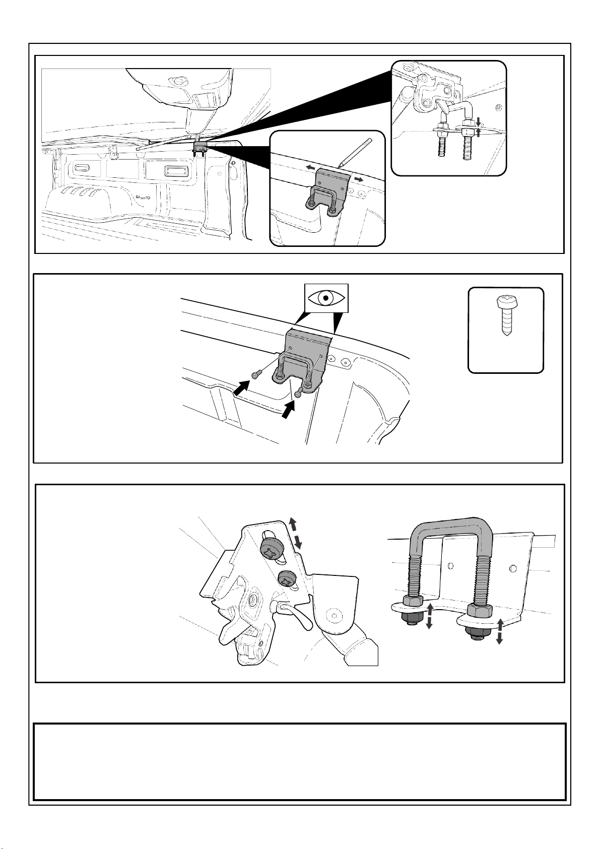
Lower lid to close position.
Align catch on lid with centre
of latch bar and mark position
of latch on bracket. Repeat
for the opposite side.
Loosen 2 screws and slide
catch to align correctly with
latch bar. Tighten screws to
secure in place.
Adjust nuts on latch bar to
alter height of bar to suit.
Repeat for the opposite
side.
Fasten latch bracket
in place with self-tapping
screws.
Repeat for the opposite
side. Self Tapping
Screws

Page 10 of 12
Q15P
Use an Allen key to loosen the hex key
screw on the catch and tension cable
so it is tight but doesn’t move the catch
at all, then re-tighten the hex key screw.
Page 11 of 12
Q15P
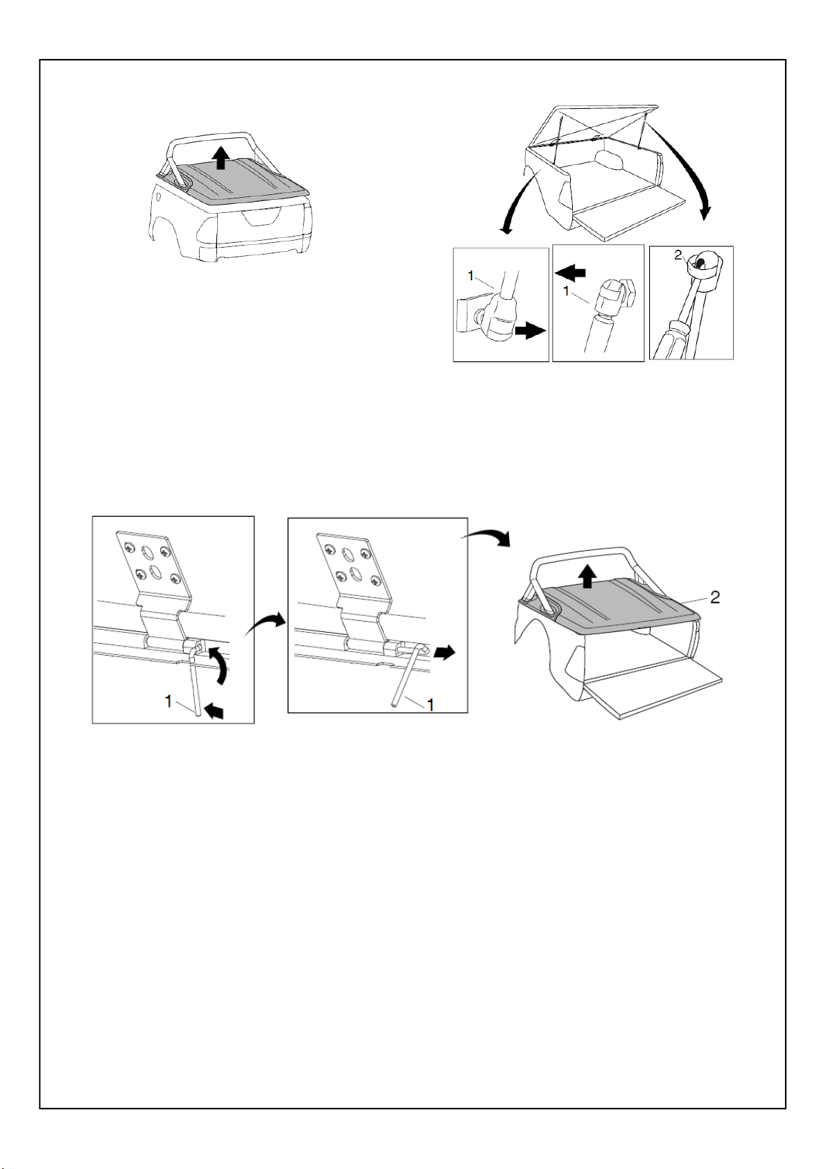
FIGURE 1
1. Open tonneau cover. Disconnect harness at front
Header bar. Detach gas strut (1) by inserting a small
screwdriver and adjusting the spring clip (2) on the
gas strut(1). Refer to figure 2.
NOTE: Do not remove the spring clip, only a small
amount of levering is required to detach. FIGURE 2
NOTE: 2 people are required to lift and re-
move the tonneau cover from the vehicle.
2. Remove hinge pins (1) and remove tonneau cover (2).
Refer to figure 3.
REMOVAL OF TONNEAU COVER
FIGURE 3
Page 12 of 12
Q15P
Having trouble? Call your Supplier.
NOTE: Please ensure Lid is kept locked at all times when not being used, for both safety and longevity.
Paint care instructions:
Your new painted Hard Tonneau Cover has been covered with a plastic film to protect the paint from damage. It will
require cleaning and possibly light polishing after the protective film has been removed. Use polish as per new paint
on a new vehicle. Wash Hard Tonneau Cover using water and normal carwash detergent and polish with an automo-
tive polish.
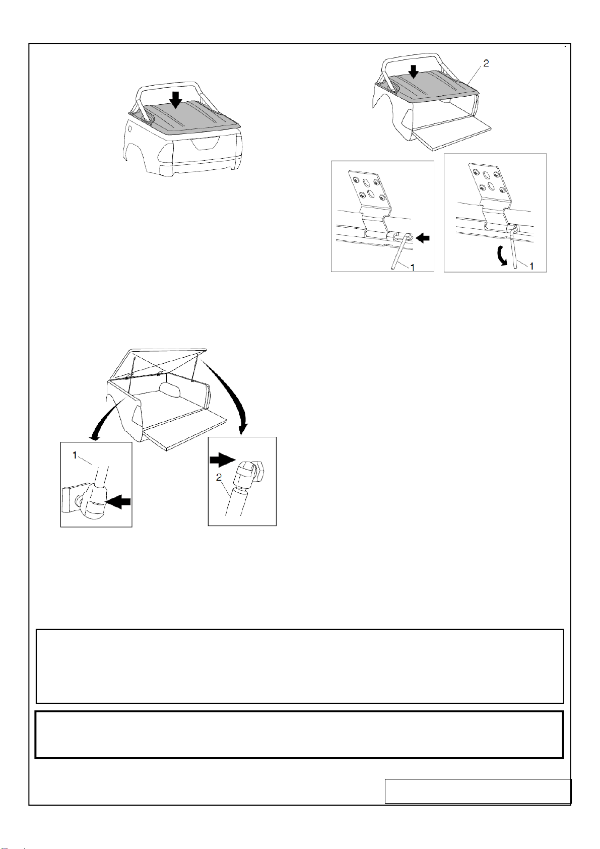
FIGURE 4
NOTE: 2 people are required to lift and fit the
tonneau cover onto the vehicle.
1. Fit tonneau cover (2) and secure hinges
with hinge pins (1). Refer to figure 5.
FIGURE 5
2. Attach gas struts (2) by clipping into place. Ensure
narrow end (1) mounts to the vehicle. Reconnect har-
ness at front header bar. Refer to figure 6.
REPLACEMENT OF TONNEAU COVER
FIGURE 6
Other Premium LID Automobile Accessories manuals


Popular Automobile Accessories manuals by other brands

NORDRIVE
NORDRIVE SNAP Steel Fitting instructions

Wells Cargo
Wells Cargo Automobile Accessories owner's manual

Thule
Thule Rapid System Kit 1540 instructions

Advent
Advent ADV8SF Operation manual

Stromberg Carlson Products
Stromberg Carlson Products CC-255 manual

Gembird
Gembird DCAM-HDM-01 Quick instruction guide


Digital Systems
Digital Systems Tytan GPS Pager DS511 user manual

bosal
bosal 033-268 Fitting instructions

Truma
Truma Mover TE R4 Operating instructions and installation instructions

Siemens
Siemens VersiCharge AC Quick start installation guide

Twinny Load
Twinny Load A 34 Fitting instructions

STO N SHO
STO N SHO SNS 214 Installation procedures