Premium Supply PH310 User manual

Power Hoist
Models
PH310, PH416, PH516, PH520, PH616-5, PH616-6, PH620, PH621-5, PH621-6,
PH625, PH630
and Trailer Jack with Hoist
Operator’s Manual and Installation Instructions
Premium Supply
2038 West Interstate 30
Greenville, Texas
866-934-0777
Proud members of:
November15, 2020

Premium Supply
Greenville, Texas
Page 2
Table of Contents
INTRODUCTION .............................................................................................................3
STANDARD WARRANTY AND WARRANTY EXTENSIONS.......................................4
SAFETY FIRST................................................................................................................5
SAFETY SIGN LOCATIONS...........................................................................................6
SAFETY PRECAUTIONS ...............................................................................................7
HOIST KIT........................................................................................................................8
SAFETY ARM INSTALLATION AND USE......................................................................9
HINGE INSTALLATION................................................................................................. 11
HOIST LOCATION ON TRAILER .................................................................................12
HOIST MOUNTING DIMENSIONS ..............................................................................13
HOIST AND HINGE GREASE POINTS .......................................................................14
SINGLE AND DUAL ACTING HYD. POWER UNIT INSTALLATION .........................15
Single Acting HPU Connections ................................................................................16
Dual Acting HPU Connections...................................................................................17
TYPICAL BATTERY HOOKUP .....................................................................................18
TRAILER JACK KIT.......................................................................................................19
SINGLE HYDRAULIC TRAILER JACK INSTALLATION ............................................20
DUAL HYDRAULIC TRAILER JACK INSTALLATION ................................................21
DUAL DOUBLE ACTING JACK AND HOIST HPU CONNECTIONS.........................22
PH310 HOIST DIMENSIONS AND CAPACITY ...........................................................24
PH416 HOIST DIMENSIONS AND CAPACITY ...........................................................26
PH516 HOIST DIMENSIONS AND CAPACITY ...........................................................28
PH520 HOIST DIMENSIONS AND CAPACITY ...........................................................30
PH520 HOIST DIMENSIONS AND CAPACITY ...........................................................30
PH616-5 & PH616-6 HOIST DIMENSIONS AND CAPACITY .....................................32
PH620 HOIST DIMENSIONS AND CAPACITY ...........................................................34
PH621-5 & 621-6 HOIST DIMENSIONS AND CAPACITY ..........................................36
PH625 HOIST DIMENSIONS AND CAPACITY ...........................................................38
PH630 HOIST DIMENSIONS AND CAPACITY ...........................................................40

Premium Supply
Greenville, Texas
Page 3
Jack Model Number:
Jack Serial Number:
Pump Installation and Operation Manual
Number:
In Service Date:
Dealer:
Address:
City, State, Zip:
Dealer Phone Number:
INTRODUCTION
This manual covers proper hoist installation, hydraulic connections, wiring and service
of the Premium Supply hoists..
NOTICE: READ THIS ENTIRE MANUAL BEFORE ATTEMPTING TO INSTALL ANY
COMPONENT CONTAINED IN THE HOIST KIT.
This manual should be kept at all times with the trailer, jack, hoist or other equip-
ment or device(s) with which this Premium Supply product is used or installed.
NOTE: Installation of Premium Supply products on your truck or trailer or other
equipment may void or aect the truck or trailer or equipment warranty – contact
the manufacturer to ensure continued warranty coverage or conditions or excep-
tions to warranty that may be aected.
Each kit contains an adhesive serial number tag which must be axed to the hoist in the
area shown.
IMPORTANT INFORMATION
Serial Number
Tag Location

Premium Supply
Greenville, Texas
Page 4
STANDARD WARRANTY AND WARRANTY EXTENSIONS
→STANDARD WARRANTY
Premium Supply makes no express warranty for this product except those specically set forth herein.
Premium Supply warrants its products to be free from defect in design, material and workmanship for a
period of 36 months from original date of purchase, and to be suitable for and to perform in accordance
with the use(s) and specications stated in product materials. This warranty supersedes all other warran-
ties. Except for warranties herein stated, there are no other warranties.
EXCLUSION OF IMPLIED WARRANTIES: PREMIUM SUPPLY MAKES NO WARRANTY OF MER-
CHANTABILITY OF THE GOODS SOLD UNDER THIS AGREEMENT. PREMIUM SUPPLY MAKES NO
WARRANTY OF FITNESS FOR A PARTICULAR PURPOSE OF THE GOODS SOLD.
This warranty applies only to parts manufactured by Premium Supply. Components not manufactured by
Premium Supply shall be covered under the original manufacturer’s warranty. Premium Supply will assist
in administering all such warranties. If a defect in a product is discovered and is covered by this warranty,
Premium Supply will have the option to repair, refurbish or replace any warrantied item(s), such option
to be exercised in Premium Supply’s sole discretion. This warranty inures to the benet of the original
purchaser only, is non-transferable, and has no cash value
→WARRANTY EXTENSIONS
If the following conditions are met, the standard warranty will be extended as stated below if (1) the
hydraulic oil is purchased from Premium Supply and (2) all single acting circuits are plumbed with a hy-
draulic hose installed on both sides of the cylinder.
4 years for battery optimizer kit that include:
20 amp. road charger with 7 way
5 amp battery charger
SP-3 – 3watt SolarPulse panel
5 years for battery optimizer heavy duty kit that includes:
20 amp. road charger with 7 way
8 amp, battery charger
SP-7-7 watt SolarPulse panel
6 years for battery optimizer extreme heavy duty kit that includes:
20 amp. road charger
18 amp. battery charger
SP-12-12 watt SolarPulse panel
→EXCLUSIONS
This warranty covers only defects in design, manufacturing and/or materials discovered while using the
product as recommended by the manufacturer. The warranty does not cover: (1) loss or theft; (2) product
failure or damage caused by user abuse or neglect, improper use, improper installation, improper mainte-
nance, improper storage, or improper or unauthorized modication(s); (3) parts that are subject to normal
wear and tear; (4) paint, nishes or paint preparation performed by anyone other than Premium Supply;
(5) deterioration of paint and/or appearance caused by normal wear and tear and/or exposure to natural
elements; (6) modications not authorized by Premium Supply; and/or (7) loss brought about by natural
disaster or acts of God. This warranty becomes VOID and of no force or eect upon modications to prod-
uct component performed by anyone other than Premium Supply if such modications are not authorized
by Premium Supply.
Premium Supply
Greenville, Texas
Page 5
SAFETY FIRST
IT IS YOUR DUTY AND RESPONSIBILITY TO COMPLETELY READ THROUGH AND
UNDERSTAND THIS MANUAL AND ALL OTHER MATERIALS PROVIDED WITH PRE-
MIUM SUPPLY PRODUCT(S)(INCLUDING MATERIALS PROVIDED BY THIRD PARTY
MANUFACTURERS) BEFORE ATTEMPTING ANY INSTALLATION OR OPERATION
OF PREMIUM SUPPLY OR THIRD PARTY PRODUCT(S) SUPPLIED BY PREMIUM
SUPPLY. IF AT ANY TIME YOU HAVE QUESTIONS ABOUT THE INSTALLATION
OR OPERATION OF PREMIUM SUPPLY OR PREMIUM SUPPLY SUPPLIED PRO-
DUCT(S) OR ABOUT THE CONTENTS OF THIS MANUAL, CONTACT PREMIUM
SUPPLY BEFORE PROCEEDING WITH THE CONTEMPLATED INSTALLATION OR
OPERATION. PREMIUM SUPPLY IS NOT RESPONSIBLE FOR PROPERTY DAMAGE
OR PERSONAL INJURY OR DEATH THAT MAY OCCUR FOR YOUR FAILURE TO
COMPLY WITH THESE REQUIREMENTS.
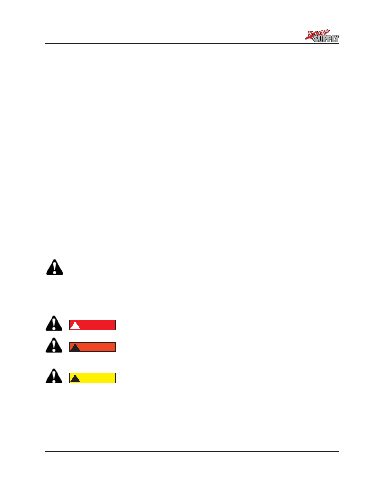
This symbol is used to call attention to instructions concerning personal
safety. Be sure to observe and follow these instructions. Take time to read
thoroughly and to be careful!
A brief description of signal words that are used in this manual follows:
DANGER
!
Indicates an imminently hazardous situation which, if not avoided,
WILL result in property damage, death or serious injury.
WARNING
!
Indicates a potentially hazardous situation which, if not avoided,
COULD result in property damage, death or serious injury and includes hazards
that are exposed when guards are removed.
CAUTION
!
Indicates a potentially hazardous situation which, if not avoided,
MAY result in property damage or minor or moderate person injury
including death. It is also used to alert against unsafe practices.
→LIMITS OF LIABILITY
Should the product fail, the sole recourse is repair or replacement, as described in the preceding para-
graphs. Premium Supply is not liable to any party for direct, indirect or consequential damage(s) resulting
from failure of the product. Under no circumstances will Premium Supply be responsible for lost prot,
lost savings, damage to other equipment, rental or replacement costs, or other incidental or conse-
quential damages arising from use or inability to use the product. Damages, if any, recoverable against
Premium Supply shall under no circumstances exceed the current list price of the product excluding tax,
shipping and handling charges
By using the product, user accepts all terms stated herein. Premium Supply re-
serves the right to make improvements to any model or product without notice.

Premium Supply
Greenville, Texas
Page 6
SAFETY SIGN LOCATIONS
Installing or operating this equipment without rst understanding proper installation and
operation procedures could lead to serious property damage, personal injury or even
death. Always read and fully understand all installation and operation manuals before
installing or operating this equipment. Contact Premium Supply with any questions.
Read all safety signs on the trailer and those included with or stated in this manual.
Keep these signs clean and replace any lost, damaged or destroyed signs.
Part 080031
Locate as shown
Part 080012B
Locate in an easy to read
location here and on
opposite frame
Premium Supply
Greenville, Texas
Page 7
SAFETY PRECAUTIONS
Installing or operating this hoist without rst understanding proper installation and opera-
tion procedures could lead to serious injury or death. Always read and fully understand
all installation and operation manuals before installing or operating this equipment. Con-
tact Premium Supply with any questions.
WARNING!
Overloading a trailer could cause vehicle or trailer component damage
resulting in injury or death. NEVER exceed the gross vehicle weight (GVW) or gross
axle weight (GAW) rating of the trailer or your vehicle.
WARNING!
Damage to brake lines during manufacturing and installation of the hoist,
as well as installing any hardware (bolts, nuts, brackets) in a way that they may rub
and damage the brake system, could lead to brake failure. This can cause an accident
that could cause injury or death. ALWAYS take adequate steps to prevent brake sys-
tem damage during installation of the hoist, and take precaution to ensure that installed
equipment does not interfere with brake system.
WARNING
!
Malfunctioning equipment could cause property damage, injury or death.
ALWAYS have faulty equipment repaired before continuing use. Consult the trailer
manufacturer if required.
WARNING!
Welding, oxy-fuel cutting, or grinding could cause fuel to ignite. This
could lead to injury or death. ALWAYS take adequate steps to avoid the ignition of fuel
from fuel tanks when welding, oxy-fuel cutting, and/or grinding during installation.
Heat from the vehicles exhaust system could cause hydraulic component failure. This
could lead to a re that can lead to injury or death. ALWAYS install equipment in loca-
tions where the exhaust system heat will not damage any components critical to opera-
tion.
WARNING
!
Never attempt to jerk or shock the trailer body with the body raised to
remove a stuck load. Jerking or shocking the trailer in this position can cause dam-
age that could result in injury or even death. NEVER drive forward or reward and stop
quickly to “un-stick” the load. If load is stuck, lower trailer body and free load.

Premium Supply
Greenville, Texas
Page 8
HOIST KIT
Hydraulic Power Unit Hinge (Styles Vary)
Safety Arm
Hoist Assembly
Safety Arm Cup Safety Arm Storage Bracket
Rubber Battery Strap Hydraulic Hose Between HPU and Cylinder
Hydraulic Fittings
Battery Cables Locking Collars
Bridon Load Control

Premium Supply
Greenville, Texas
Page 9
SAFETY ARM INSTALLATION AND USE
Always support an unloaded body with the safety arm. The safety arm
is meant to support the weight of an unloaded body only.
DANGER
!
Being under a raised body could result in serious injury or death should
the body unexpectedly descend. Never position yourself or allow others to position
themselves under a loaded body. Always support an unloaded body with the supplied
safety arm. NEVER use the safety arm on a loaded body.
Safety Arm Use:
1. Raise trailer body to sucient height and shut o hydraulic power to hoist.
2. Grasp safety arm and rotate into the up/vertical position.
3. Once vertical position is accomplished, push arm down into the support bracket at
base of arm.
4. SLOWLY lower the hoist and body until the cup contacts the vertical facing arm.
5. Reverse the above procedure to place arm back in its hanger for transport (be sure
to lower hoist to full down position upon placing arm back in hanger).
Maximum Unloaded Tilt Body Weight in Pounds Using One Safety Arm
Trailer tilt body length in feet
Distance between rear hinge and safety arm in inches
8 10 12 14 16 18 20
50 3854 3083 2569 2202 1927 1713 1542
60 4625 3700 3083 2643 2313 2056 1850
70 5396 4317 3597 3083 2698 2398 2158
80 6167 4933 4111 3524 3083 2741 2467
90 6938 5550 4625 3964 3469 3083 2775
100 6167 5139 4405 3854 3426 3083
110 6783 5653 4845 4240 3769 3392
120 7400 6167 5286 4625 4111 3700
130 6681 5726 5010 4454 4008
140 7194 6167 5396 4796 4317
150 6607 5781 5139 4625
160 7048 6167 5481 4933
170 6552 5824 5242
180 6938 6167 5550
190 7323 6509 5858
200 6852 6167
210 7194 6475
220 6783
230 7092

Premium Supply
Greenville, Texas
Page 10
Weld along this
edge
Safety Arm
Weld along
this edge
Weld along
this edge
Safety arm in
storage position
Cup for Safety Arm

Premium Supply
Greenville, Texas
Page 11
HINGE INSTALLATION
NOTE: Style of hinge could vary from that shown.
Mount hinge so pad of
hinge is level with trailer
frame.
Center hinge on support
and weld hinge to support
at all contact surfaces.
small hinge grease

Premium Supply
Greenville, Texas
Page 12
HOIST LOCATION ON TRAILER
M dimension, see
hoist dimension
and capacity
pages
Center hoist assembly on trailer frame
Center line of lower hoist pivot A
Hoist Model Dimension A
PH310 27”
PH416 38”
PH516 38”
PH520 46”
PH616 38”
PH620 47”
PH621 46”
PH625 52”
PH630 60”
26.5” Max. for 310,416,516,520,616,621
28.0 Max. for 620,625,630
Locking collar
typical other side
19.13” for 310,416,516,520
24.88” for 616,620,621,625,630

Premium Supply
Greenville, Texas
Page 13
HOIST MOUNTING DIMENSIONS
Hoist Tab
Nearest frame member
with tilt frame down
A
B
A B
PH310 5.5 -------
PH416 7.00 -------
PH516 7.00 -------
PH520 7.00 -------
PH616 8.00 -------
PH620 8.00 13.00
PH621 7.00 -------
PH625 8.00 13.00
PH630 8.00 13.00
Weld or bolt plate to tilt
frame.
Weld or bolt supports
to cross member.

Premium Supply
Greenville, Texas
Page 14
HOIST AND HINGE GREASE POINTS
Grease tting locationGrease tting location
Lubricate the joint with EP3 grease every 6 months
small hinge grease
Grease tting location

Premium Supply
Greenville, Texas
Page 15
SINGLE AND DUAL ACTING HYD. POWER UNIT INSTALLATION
If included with the kit, mount HPU (hydraulic power unit) in a weather tight enclosure
on the trailer. See additional instructions supplied with the HPU for mounting, electrical,
wireless remote and hydraulic uid requirements.
CAUTION
!
Hydraulic components that are not provided by Premium Supply and
are used in the hydraulic circuit that are incompatible with Premium Supply components
may cause damage to, or failure or malfunction of, the direct push cylinder or other
components of the Premium Supply product(s). Such damage, failure or malfunction
may cause property damage, personal injury or even death, It is the purchaser’s
responsibility to verify the compatibility of components not provided by Premium Supply.
Connecting the jack to a hydraulic system with more
pressure (PSI) or ow (GPM) than is recommended by Premium Supply could cause
the jack to fail during operation. Such failure could cause property damage, personal
injury, or even death. Ensure that you have pressure that does not exceed tolerances
and limits stated for your Premium Supply product(s)/component(s), and that there is
no restriction or issue concerning ow before operation. Consult Premium Supply if
you are unsure about the limits, capacities and/or tolerances of your hydraulic system.
WARNING
!
Adjusting the hydraulic pressure to exceed the recommended
limits or setting could cause the jack to fail during operation. Such failure could cause
property damage, personal injury, or death. Pressure should ONLY be adjusted by a
trained and qualied technician or mechanic, and should never exceed stated limits or
settings of components used.
Hydraulic System Pre-Operation
The hydraulic system supplied by Premium Supply consists of components (pump,
valves, reservoir, hoses, cylinder, etc.) that are designed to be compatible with each
other.
All Premium Supply’s liability and warranty will be voided if determined by Premium
Supply that substituted hydraulic components (i.e., hydraulic components not
provided by Premium Supply as part of the kit) were used and such components
were incompatible with components of the kit provided by Premium Supply.
Hydraulic parameters are shown below. These are listed as a general
guide to ensure proper compatibility (when using other hydraulic components). If you
have any questions about component compatibility, please contact Premium Supply
before installation, use or maintenance.
Maximum Working Pressure---3200 PSI
Hydraulic Port Type--#6 JIC
WARNING
!

Premium Supply
Greenville, Texas
Page 16
Maximum Hydraulic Flow Rate 2 GPM Port
Maximum Pressure For “Raising” Portion of Cycle 3200 PSI A
Single Acting HPU Connections
Hoist
Cylinder
IMPORTANT:
Install (supplied) Bridon
load control valve at this
port of hydraulic cylinder
Install vented plug (supplied) in this
port. To qualify for extended warranty
a hose must be installed here. Contact
Premium Supply for instructions.

Premium Supply
Greenville, Texas
Page 17
Maximum Hydraulic Flow Rate 2 GPM Port
Maximum Pressure For “Raising” Portion of Cycle 3200 PSI A
Maximum Pressure For “Lowering” portion of Cycle 1500 PSI B
Dual Acting HPU Connections
Hoist
Cylinder
Body Up Hose Assy.
110”x3/8 (Supplied)
Port “A” On hydraulic
power unit 3200 PSI
IMPORTANT:
Install (supplied) Bridon
load control valve at this
port of hydraulic cylinder
Body Down Hose Assy.
120”x3/8 (Supplied)
Port “B” On Hydraulic power
unit 1500PSI

Premium Supply
Greenville, Texas
Page 18
TYPICAL BATTERY HOOKUP
WARNING
!
Shorting of the electrical system brought about by installation, servicing
or repairing battery related connection and electrical components can cause sparks,
ignition of combustible material and/or re which in turn can lead to property damage,
personal injury or death. ALWAYS disconnect the battery prior to installing, servicing, or
repairing power unit.
Mount battery in a weather tight enclosure on the trailer. See additional instructions sup-
plied with the HPU for mounting, electrical and hydraulic uid requirements.
It is highly recommended that the trailer battery be kept charged using one of the Pulse-
tech products shown on Premium supply website at http://www.premium-supply.com/

Premium Supply
Greenville, Texas
Page 19
TRAILER JACK KIT
Hydraulic Power Unit Trailer Jack
Rubber Battery Strap Hydraulic Hoses Between HPU and Jack
Hydraulic Fittings Battery Cables
Flow Divider
(Dual Jack Kit Only)

Premium Supply
Greenville, Texas
Page 20
Continuous weld both
sides of jack
8” Maximum
SINGLE HYDRAULIC TRAILER JACK INSTALLATION
This manual suits for next models
10
Table of contents


