WARNINGS
Do not connect power supply until fan is completely
installed. Make sure electrical service to the fan is
locked in “o” position.
1. Remove unit from packaging and inspect within 15
days after receipt. If damaged, report damage to
carrier. Do NOT operate this unit with visible
damage to the blower or impeller assembly
2. All products with A/C motors installed are
suitable for use with solid state speed control.
3. This unit has rotating parts and safety
precautions should be exercised during
installation, operation and maintenance.
4. CAUTION: “For General Ventilation Use Only. Do
Not Use To Exhaust Hazardous Or Explosive
Materials and Vapors.”
5. WARNING!To reduce the risk of re, electric
shock, or injury to persons- observe the following:
a. Use this unit only in the manner intended by the
manufacturer. If you have questions, contact the
manufacturer.
b. Before servicing or cleaning, switch power o at
the service panel and lock service panel to prevent
fan from being switched on accidentally.
c. Installation work and electrical wiring must be
done by qualied person(s) in accordance with all
applicable codes and standards, including re-
rated construction.
d. Sucient air ow is needed for proper combustion
and exhausting of gases through the ue
(chimney) of fuel burning equipment to prevent
backdrafting. Follow the heating equipment
manufacturer’s guidelines and safety standards
such as those published by the National Fire
Protection Association (NFPA), the American
Society of Heating, Refrigeration, and Air
Conditioning Engineers (ASHRAE) and the local
code authorities.
e. When cutting or drilling into a wall or ceiling, do
not damage electrical wires or other hidden
utilities.
f. Ducted fans must always be vented to the
outdoors.
g. Install fan at least ve feet above the oor.
h. NEVER place a switch where it can be reached
from a tub or shower.
6. WARNING!Check voltage at the fan to see if it
corresponds to the motor nameplate.
7. Guards must be installed when this fan is within
reach of personnel or within seven (7) feet of
working level or when deemed advisable for safety.
Fan installation
Step 1
When selecting the fan mounting location, the following criteria should be considered: a) type of
application; b) proximity to fresh air intakes; c) sound created by fan operation.
Select the location on the exterior wall where the fan is to be mounted. Make a hole through the
wall that is 1/2” larger than the diameter of the fan duct connection collar. A short piece of rigid
duct (not included) approximately 2” longer than the wall thickness is recommended for use as an
extension through the wall.
Step 2
Remove the four screws securing the white fan discharge cover and remove the cover. Place the
fan against the wall, as centered as possible on the wall opening, then mark the location of the
four backplate mounting holes and the electrical knockout. Drill a hole for the electrical service
that is 1/8” larger than the size of conduit to be used. A 1” diameter electrical service opening is
provided on the fan backplate (see dimensional drawing on Page 1). When mounting the fan on a
masonry wall, drill 7/32” holes for the four anchors and mounting screws (provided). Tap the
anchors ush into the holes. When mounting the fan on a wood surface, wood screws should be
used.
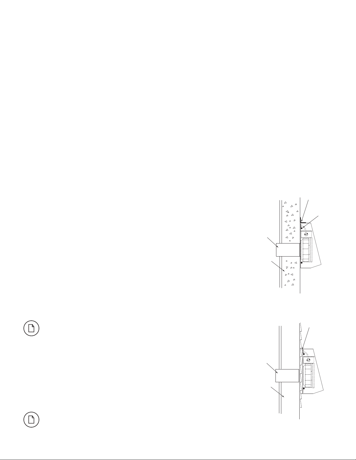
If the fan is to be mounted on a wall surface which is Lapped Siding, a mounting frame
made from 1x1 board may be necessary for a ush t (see I-2).
Step 3
Before mounting the fan, bring the electrical supply through the wall. Attach the extension collar
to the fan duct connection collar. The connection should be as air tight as possible to prevent
leakage from the wall cavity. Apply a generous amount of polyurethane caulk to the exterior side of
the fan housing backplate (except the bottom so that water that leaked in can drain back out).
This will ensure an airtight/waterproof connection between the fan and the wall surface. If a
mounting frame is used in conjunction with lapped siding, be certain to apply a generous amount
of caulk between the frame and the wall as well as the fan backplate and the frame. Mount the fan
to the wall.
Be certain to make an airtight seal around all interior wall penetrations before
attaching duct work.
Extension Collar
through wall
Masonry Wall
Optional Standard Fange
Discharge
Cover
Mounting
Screws
Figure 1
Extension Collar
Lapped Siding
Wall
Mounting
Frame
Figure 2