Presto GEOSYSTEMS GEOWEB Instruction sheet

PRESTO
PRESTO GEOSYSTEMS®
670 NPERKINS STREET,APPLETON,WISCONSIN,USA 54914
Ph: 920-738-1328 or 800-548-3424 ■Fax: 920-738-1222
e-mail: INFO@PRESTOGEO.COM WWW.PRESTOGEO.COM/
GWLS000 18-APR-2011
GEOWEB®
LOAD SUPPORT SYSTEM
INSTALLATION GUIDELINE
Distributed by: Bowman Construction Supply, 10801 E. 54th Avenue, Denver, CO 80239; Phone: (303) 696-8960

PRESTO
GEOWEB®
LOAD SUPPORT SYSTEM
INSTALLATION GUIDELINE
GW/LS000 18-APR-2011 COPYRIGHT 2011 –PRESTO PRODUCTS CO.
Table of Contents
Subgrade Preparation ...................................................................................................................................1
Figure 1 Unpaved Access .....................................................................................................................1
Figure 2 Flexible Pavement ..................................................................................................................1
Figure 3 Trackbed Stabilization ............................................................................................................1
Figure 4 Pipeline Support......................................................................................................................1
Figure 5 Spread Footing .......................................................................................................................1
Geotextile Underlayer....................................................................................................................................1
Figure 6 Geotextile Placement..............................................................................................................1
Installation of Geoweb® Sections .................................................................................................................2
Figure 7 Stake Anchorage ....................................................................................................................2
Figure 8 ATRA®Anchor Placement Options.........................................................................................2
Figure 9 Infilling Perimeter Cells ...........................................................................................................2
Figure 10 Use of Stretcher Frame ........................................................................................................2
Installation of Geoweb® Sections on Curves................................................................................................3
Figure 11 Curved Expansion of Section ...............................................................................................3
Figure 12 Tapered Expansion of Section..............................................................................................3
Connecting Geoweb® Sections ....................................................................................................................3
Figure 13 ATRA® Key Connection Device ...........................................................................................3
Placement and Compaction of Geoweb® Infill .............................................................................................4
Figure 14 Fill Placement with Loader....................................................................................................4
Figure 15 Fill Placement with Excavator...............................................................................................4
Figure 16 Infill Compaction ...................................................................................................................4
Dimensions and Weights of Palletized Geoweb® Sections..........................................................................4
Table 1 V-Series Geoweb®Shipping Dimensions and Weights ...........................................................4
Infill Volumes .................................................................................................................................................5
Table 2 Infill Volumes for Geoweb®Sections .......................................................................................5
Tools and Equipment ....................................................................................................................................5
Table 3 Standard Construction Tools for Installation of the Geoweb®System ....................................5
Excavation and Materials Handling Equipment.........................................................................................5
Compaction Equipment .............................................................................................................................5
Limited Warranty ...........................................................................................................................................6
PRESTO
GEOWEB®
LOAD SUPPORT SYSTEM
INSTALLATION GUIDELINE
GW/LS000 18-APR-2011 COPYRIGHT 2011 –PRESTO PRODUCTS CO. PAGE 1OF 6
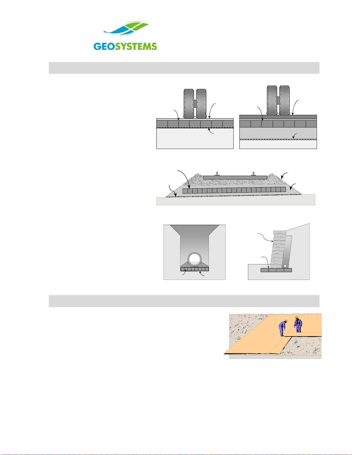
Subgrade Preparation
Geoweb®load support applications are
generally classified as follows and
illustrated in Figure 1 - Figure 5:
1. Unpaved access roads and hard-
standing areas.
2. Base and subbase stabilization of
flexible pavement structures.
3. Stabilized trackbed structures.
4. Raft construction on soft soils.
5. Structural spread footings.
The extent and nature of subgrade
preparations depend on the type of
structure and the subsoil conditions.
•Paved roads, railroad trackbeds
and structural footings require
accurate grading, shaping and
proof-rolling of the subgrade soils.
•Provision of adequate cross-fall or
crowning at formation level is
particularly important.
•Raft construction, involving
extremely weak compressible
subsoils, generally limits subgrade
preparation work to the clearing of
large vegetation. Any existing root
mass is normally left intact.
Geoweb
Section
Subgrade
Geotextile
Gravel
Surcharge
Figure 1 Unpaved Access
Geoweb
Section
Granular Base
Subgrade
Geotextile
Flexible
Pavement
Figure 2 Flexible Pavement
Geoweb
Section Primary
Ballast
Geotextile Sub-ballast
Figure 3 Trackbed Stabilization
Geoweb
Section Geotextile
Figure 4 Pipeline Support
Geoweb
Section
Spread
Footing
Modular Concrete
Retaining
Wall
Figure 5 Spread Footing
Geotextile Underlayer
•Most load support applications involve a geotextile separator
layer at the subgrade surface. When required, this
separation layer is critical to the performance of the load
support system.
•Ensure that minimum overlap between rolls is maintained.
See Figure 6.
•The geotextile may also function as a lateral drainage
medium. A thick, non-woven geotextile or geo-composite
materials are then required. Figure 6 Geotextile Placement
•High-strength geotextiles are used when building Geoweb®
structures over soft compressible soils. Pre-sewn seams,
rather than overlapped joints, may be required in some
situations.

PRESTO
GEOWEB®
LOAD SUPPORT SYSTEM
INSTALLATION GUIDELINE
PAGE 2OF 6 COPYRIGHT 2011 –PRESTO PRODUCTS CO. GW/LS000 18-APR-2011
Installation of Geoweb® Sections
•Option 1: Expand the specified Geoweb®section
into position and anchor with stakes.
See Figure 7. When ATRA®Anchors are used,
ensure the ATRA®Clip arm is hooked over the cell
wall or placed through the cell-wall slot hole. See
Figure 8.
•Specialized driving tools are available through
Presto Geosystems’ authorized distributors and
representatives to speed driving of ATRA anchors.
•Option 2: Expand and manually fill selected
perimeter cells prior to machine infilling.
See Figure 9.
•Option 3: The use of stretcher frames is
generally recommended only for underwater or
extremely cold applications.
Expand and fit the Geoweb®section over the
dowels of a suitably dimensioned stretcher frame.
Invert the frame and position the section to receive
infill material. When the Geoweb®section is filled,
remove the frame and repeat the process.
See Figure 10.
Figure 7 Stake Anchorage
Figure 8 ATRA®Anchor Placement Options
Figure 9 Infilling Perimeter Cells
Figure 10 Use of Stretcher Frame

PRESTO
GEOWEB®
LOAD SUPPORT SYSTEM
INSTALLATION GUIDELINE
GW/LS000 18-APR-2011 COPYRIGHT 2011 –PRESTO PRODUCTS CO. PAGE 3OF 6
Installation of Geoweb® Sections on Curves
Over-expand
the outer cells
Under-expand
the inner cells
Direction
of Geoweb
section expansion
Direction
of Geoweb
section expansion
Figure 11 Curved Expansion of Section
Under-expand
the outer cells
Over-expand
the inner cells
Direction of
Geoweb section
expansion
Direction of
Geoweb section
expansion
Figure 12 Tapered Expansion of Section
Method 1: Geoweb® sections can be readily adapted to
cover curved areas by varying the degree of cell
expansion across the width of individual sections.
See Figure 11.
Method 2: Progressively vary the degree of
cell expansion along the length of a section.
See Figure 12.
Connecting Geoweb® Sections
Figure 13 ATRA® Key Connection
Device
•Verify that the expanded dimensions of each Geoweb®
section are correct.
•Interleaf sides and abut ends of adjoining sections, ensuring
that the upper surfaces of adjoining sections are flush.
•Connect each of the interleaved and abutted cells with the
ATRA® key connection device. Position the ATRA key
through the slots of overlapping sections (side-to-side), or
where cells connect (end-to-end), and turn key to “lock” in
position. See Figure 13.
•When Geoweb sections are connected end-to-end, under-
expand a few rows of the adjoining section to allow easy
placement of the ATRA keys before fully expanding the
connecting section. For easiest placement, insert the key
completely through one cell before inserting through the
adjoining cell. Adjoining sections should also be fully
connected prior to infilling.
•The use of the ATRA key device will reduce construction
time significantly and offers cost-savings compared to
stapling operations.
•Geoweb sections may also be connected with pneumatic
staplers either side-to-side or end-to-end.
•The ATRA key connection device and pneumatic staplers
are available through Presto Geosystems and their
authorized distributors/representatives.
PRESTO
GEOWEB®
LOAD SUPPORT SYSTEM
INSTALLATION GUIDELINE
PAGE 4OF 6 COPYRIGHT 2011 –PRESTO PRODUCTS CO. GW/LS000 18-APR-2011
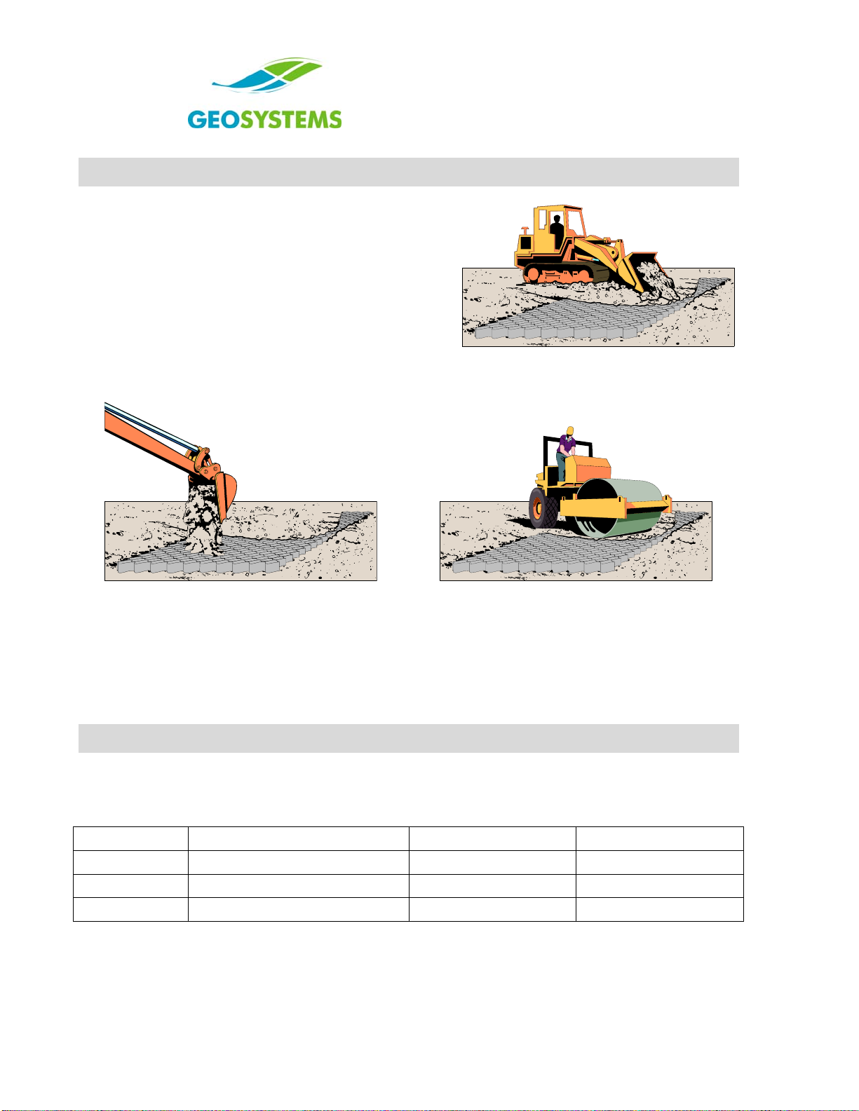
Placement and Compaction of Geoweb® Infill
•Place fill into expanded cells with suitable material
handling equipment such as a front-end loader or
excavator. See Figure 14 and Figure 15.
•Limit drop-height of infill material to a maximum of
1 m (3 ft).
•Overfill Geoweb®sections at least 50 mm (2 in) above
the cell walls before trafficking or compacting.
•Compact infill material to the specified density with
conventional compaction equipment. See Figure 16.
See Compaction Equipment on page 5 for limitations.
Figure 14 Fill Placement with Loader
Figure 15 Fill Placement with Excavator
Figure 16 Infill Compaction
Upon completion of the installation, ensure that an aggregate surcharge of at least 10 mm (0.4 in) is
maintained above the Geoweb®cell walls at all times.
Unbound aggregate surfacing must be graded and maintained on a regular basis.
NOTE: When pea gravel or other highly rounded stone is used for the infill and will have direct traffic over
the surface, blend it with 40%-45% sand to prevent excessive movement of the material.
Dimensions and Weights of Palletized Geoweb® Sections
Geoweb®sections are normally tri-folded and palletized for shipment to the site. Table 1 provides typical
pallet dimensions and weights for a range of section and cell sizes.
Table 1 V-Series Geoweb®Shipping Dimensions and Weights
Cell Depth Pallet Dimensions Minimum Weight Maximum Weight
100 mm (4 in) 1070 mm x 1070 mm (42 in x 42 in) 400 kg (880 lb) 730 kg (1,600 lb)
150 mm (6 in) 1070 mm x 1070 mm (42 in x 42 in) 360 kg (800 lb) 660 kg (1,450 lb)
200 mm (8 in) 1070 mm x 1070 mm (42 in x 42 in) 400 kg (880 lb) 730 kg (1,600 lb)

PRESTO
GEOWEB®
LOAD SUPPORT SYSTEM
INSTALLATION GUIDELINE
GW/LS000 18-APR-2011 COPYRIGHT 2011 –PRESTO PRODUCTS CO. PAGE 5OF 6
Infill Volumes
Table 2 Infill Volumes for Geoweb®Sections
Cell Depth 100 mm (4 in) 150 mm (6 in) 200 mm (8 in)
Volume (m³/ 100 m² of area) 10.0 m315 m320.0 m3
Volume (yd³/ 100 yd² of area) 11.1 yd³ 16.7 yd³ 22.2 yd³
Tools and Equipment
Installation efficiency is greatly improved by the appropriate choice of construction equipment and tools.
The following guidelines apply to most Geoweb®system applications. Non-standard tools and equipment
may provide additional benefits in some situations.
Table 3 Standard Construction Tools for Installation of the Geoweb®System
Geoweb® Components Power Tools Concrete Finishing Surveying Equipment
ATRA® Clips/Anchors Heavy-duty drill Bull floats Surveyor’s auto-level
ATRA® Connection Device Circular saw Hand floats Tripod and rod
Hand Tools Percussion hammer Steel trowels Laser beacons
Shovels and spades Stanley-Bostitch stapler Poker vibrators Audio target receiver
Rakes and screed bars SB103020 wire staples Tamping rods Survey stakes
Sledge hammers Gas generator Markers + spray cans
Crowbars Air compressor String-lines + spirit level
Utility knives
Spikes, nails + lumber
Templates
Excavation and Materials Handling Equipment
Conventional excavators, front-end loaders, mini-excavators and skid-steer loaders, equipped with
smooth-edged buckets, are normally employed for the installation of Geoweb®systems. Infilling of
Geoweb®sections can also be carried out with conveyors, chutes and skips. As a rule, the overall rate of
installation relates directly to the speed and efficiency of infill placement and compaction.
Compaction Equipment
Fully compacted infill is critical to the performance of the load support systems. When building a load
support system over a very soft subbase, a wave may occur in the system during the compaction
process. If the wave continues while compacting, full compaction will not be obtained. To remedy this
situation, the use of lighter compaction equipment is mandatory.

PRESTO
GEOWEB®
LOAD SUPPORT SYSTEM
INSTALLATION GUIDELINE
PAGE 6OF 6 COPYRIGHT 2011 –PRESTO PRODUCTS CO. GW/LS000 18-APR-2011
Limited Warranty
Presto Geosystems warrants each Geoweb®section which it ships to be free from defects in materials
and workmanship at the time of manufacture. Presto’s exclusive liability under this warranty or otherwise
will be to furnish without charge to Presto's customer at the original f.o.b. point a replacement for any
section which proves to be defective under normal use and service during the 10-year period which
begins on the date of shipment by Presto. Presto reserves the right to inspect any allegedly defective
section in order to verify the defect and ascertain its cause.
This warranty does not cover defects attributable to causes or occurrences beyond Presto's control and
unrelated to the manufacturing process, including, but not limited to, abuse, misuse, mishandling,
neglect, improper storage, improper installation, improper alteration or improper application.
PRESTO MAKES NO OTHER WARRANTIES, EXPRESS OR IMPLIED, WRITTEN OR ORAL,
INCLUDING, BUT NOT LIMITED TO, ANY WARRANTIES OR MERCHANTABILITY OR FITNESS FOR
ANY PARTICULAR PURPOSE, IN CONNECTION WITH THE GEOWEB®SYSTEM. IN NO EVENT
SHALL PRESTO BE LIABLE FOR ANY SPECIAL, INDIRECT, INCIDENTAL OR CONSEQUENTIAL
DAMAGES FOR THE BREACH OF ANY EXPRESS OR IMPLIED WARRANTY OR FOR ANY OTHER
REASON, INCLUDING NEGLIGENCE, IN CONNECTION WITH THE GEOWEB®SYSTEM.
Geosystems®, Geoweb®, and ATRA® are registered trademarks of Presto Products Company.
Distributed by: Bowman Construction Supply, 10801 E. 54th Avenue, Denver, CO 80239; Phone: (303) 696-8960
Table of contents
Other Presto GEOSYSTEMS Construction Equipment manuals


