REV086-13
WARNING: Failure to read and follow these installation instructions and safety precautions could result in personal injury, equipment damage,
shortened service life or unsatisfactory equipment performance. All information in this document is vital to the proper installation and operation of
the equipment. It is important that all personnel who will be coming in contact with this product thoroughly read and understand this manual.
US High Frequency
Electric Vibrators
VIBCO
INSTRUCTION MANUAL
For custom mounting
applications or any other questions:
800-633-0032
or
9 ELECTRICAL INSTALLATION
12 TROUBLESHOOTING
10 CHANGING OUTPUT SETTINGS
Warranty
All warranty claims must be submitted to VIBCO for approval prior to any repairs being done. Failure to do so will void any and all warranty coverage. All repairs will be done at the VIBCO factory.
Errors, Shortages & Complaints
Complaints concerning goods received or errors should be made at once. Claims must be made within ve days after receipt of goods. Clerical errors are subject to correction. Damage during shipping must be
reported to the carrier, not VIBCO.
Returning Parts **
Parts should not be returned to VIBCO without prior authorization. Call VIBCO’s customer service department at 800-633-0032 (800-465-9709 in Canada) for a Return Goods Authorization (RGA) number. A re-
turn authorization will be emailed or faxed to you. Use this as your packing slip. Return shipping must be prepaid. Material returned may be subject to a 10% restocking fee. All returned shipments should clearly
display your name, address and original invoice number to ensure proper credit.
** Orders for custom equipment built to customer’s specications are not returnable.
Product Changes
VIBCO reserves the right to make changes in pattern, design or materials when deemed necessary, without prior
notice or obligation to make corresponding changes in previous models. To be sure of exact mounting dimensions,
it is recommended that you obtain a certied dimensional drawing from the factory.
Ordering Spare Parts
Parts can be ordered through authorized distributors or from VIBCO’s Spare Parts Department. The following data
should be provided when placing your spare parts order:
From label: Model number of unit.
From spare parts list: Reference number, part number, description & quantity required.
Shipping instructions: Specify shipping point and method of shipping.
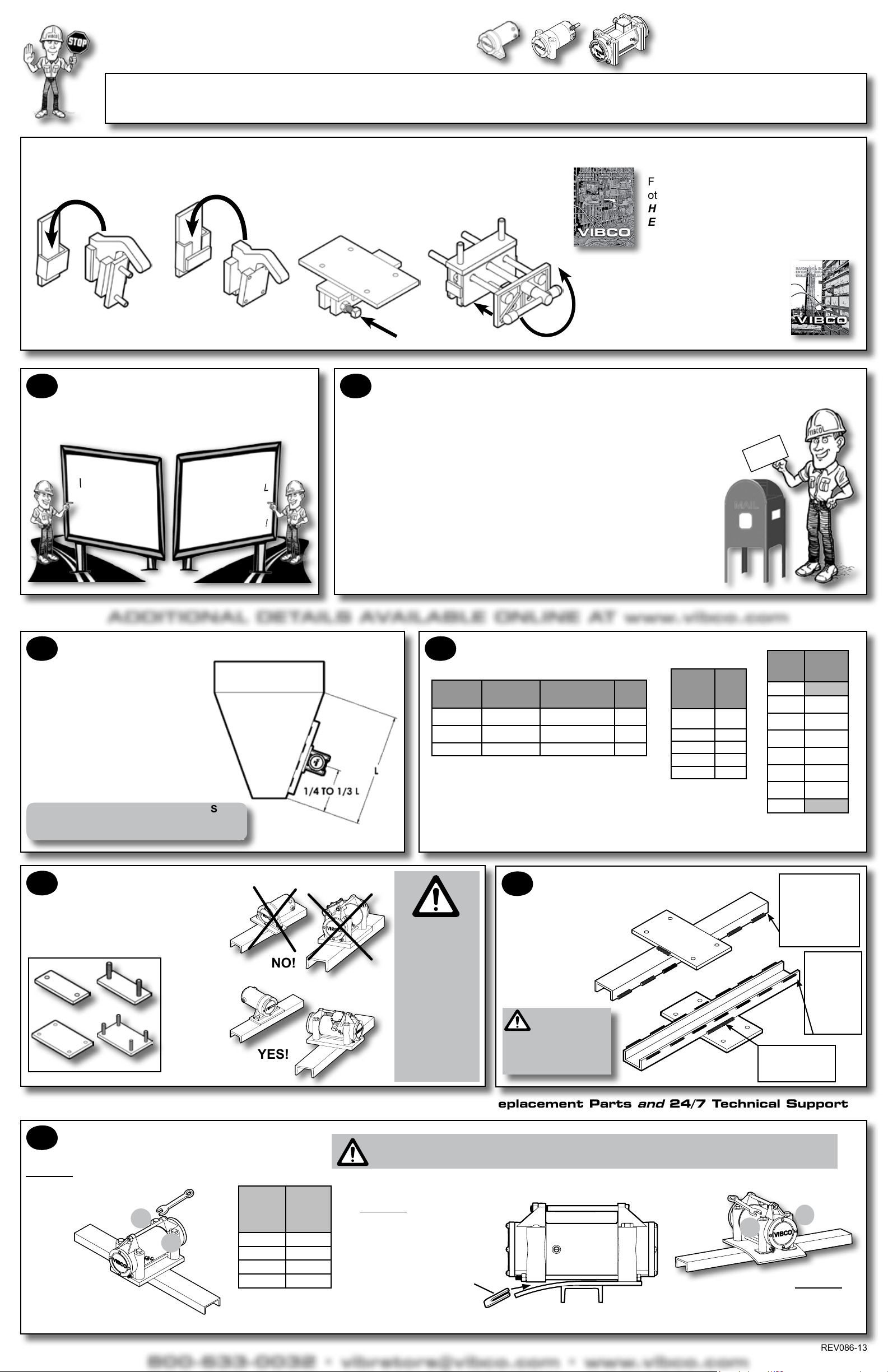
8RESTRAINT
ALWAYS INSTALL
SAFETY
CABLE or CHAIN
Mount one end to the
vibrator and the other to
the hopper or bin
above the vibrator
NEVER ATTACH TO THE
MOUNTING PLATE!
ADDITIONAL DETAILS AVAILABLE ONLINE AT www.vibco.com
Operating amperage should not exceed the value listed on the vibrator label. If
it does, it is most likely due to faulty mounting. Check your mounting welds, and
re-tighten bolts if necessary. See TROUBLESHOOTING for more info.
and then . . . TAKE AN AMPERAGE
READING WHILE THE VIBRATOR
IS RUNNING
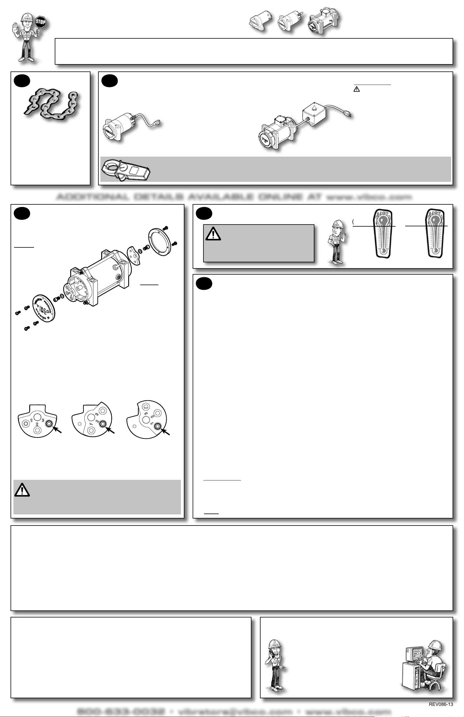
WITHOUT SWITCH BOx WITH SWITCH BOx
All US Models are single phase, 50/60 Hz. Standard 115 volt
units can simply be plugged into a grounded circuit. 230 volt
units are shipped without a plug and require hardware and/or
plug to connect to your circuitry. Always
consult professional electricians with
any questions or concerns for
electrical installations.
11 OPERATING TEMPERATURE
If the ambient temperature of the
area exceeds 104°F (40°C) OR if the
skin temperature of the application
exceeds 150°F (66°C), consult VIBCO for
alternate solutions.
104°F
(40°C)
MAxIMUM
FORCE
Intermittent Duty Only
FACTORY
SETTING
Intermittent Duty Only
CAP
SCREW
To change the force:
Disconnect power and remove both end covers.1)
Remove the cap screw that holds the outer eccentric to the inner eccentric2)
and turn the outer eccentric so that the numbered hole aligns with the
threaded hole in the inner eccentric. NOTE: You must set both ends of
the vibrator to the same setting.
Apply Loctite 242 (or equivalent). Replace the cap screw.3)
Replace both end covers. End cover bolts have a locking patch and do not4)
need Loctite.
NOTE: Models US-100, 450 and
700 have xed eccentrics and
are NOT adjustable.
Consult factory for
alternate force
options. NOTE: The
frequency of
all US Models
can be controlled by
using Model SPC speed
control box. Consult VIBCO
for further information.
MODELS: US-900 & US-1600
MINIMUM
FORCE
Intermittent Duty Only
(Optimum Setting for
Long Life of Vibrator)
CAP
SCREW
CAP
SCREW
NOTE: If you INCREASE force of vibrator, you MUST take a new
amperage draw reading to ensure vibrator is still operating within
specied limits.
NOTE: Only run intermittently (maximum running time of 30 min in any one hour
period. (See DUTY CYCLE section in Trouble Shooting section right).
VIBRATOR WON’T EVEN START?
1. Check power supply to unit. Are you getting the proper voltage? Has the thermal overload protection tripped?
2. Check vibrator brushes for wear. Each unit has two brushes. Refer to full detail manual at www.vibco.com for correct
brush lengths. Replace if worn below minimum length.
3. Check eld & armature continuity. If either is burned or has a short, replace. If unsure how to check continuity, call
VIBCO or consult a licensed electrician.
DID THE VIBRATOR STOP RUNNING?
1. Check power supply to unit.
2. FOR Model US-900 & 1600 ONLY -- Has the thermal overload protection tripped? If overload protection has tripped,
wait a minimum of two (2) minutes then reset by switching rmly off and then on again.
3. Is there an unusual sound (banging) coming from the vibrator? This usually means that the vibrator has loosened or
the mounting is cracked.
Check the vibrator mounting bolts for tightness.
Check the mounting structure. New installations may be too weak. Reinforce mount area immediately by adding
stiffeners like angle iron or channel iron.
In existing installations look for cracks in mounting angle iron or plates. Also look for fatigued or cracked welds.
Repair and reinforce immediately.
Check vibrator and bracket connection to the form or mold. If clamps are loose or wedge is not properly inserted, it
may cause vibrator to run hot and cause internal damage. Brackets may need to be adjusted or replaced.
4. Check vibrator brushes for wear. Each unit has two brushes. Refer to full detail manual at www.vibco.com for correct
brush lengths. Replace if worn below minimum length.
5. Are you running the vibrator continuously? All VIBCO high frequency electric models are rated for intermittent duty
only.
NOTE: Consult VIBCO for available timers to help run vibrators at proper intervals.
6. Are you repeatedly stopping and starting the vibrator? This can overload the vibrator. Use the following guidelines for
proper timing of starts and stops:
DUTY CYCLE
All US Models are rated for INTERMITTENT DUTY only.
Use 50% duty cycle where maximum run time = 30 minutes in any one hour period.
For run times of 10 seconds or less, use 1:7 ratio for run time vs. off time. (example: 5 seconds on to 35 seconds off).
For run times longer than 10 seconds, any cycle is acceptable.
NOTE: Duty cycle can be increased by adding additional ventilation. Consult VIBCO for details.
150°F
(66°C)
SKIN TEMPAMBIENT TEMP
DUTY CYCLE
All US Models are rated for
INTERMITTENT DUTY only.
Use 50% duty cycle where maximum run
time = 30 minutes in any one hour period.
For run times of 10 seconds or less,
use 1:7 ratio for run time vs. off time.
(example: 5 seconds on to 35 seconds
off). For run times longer than 10
seconds, any cycle is acceptable.