Presto GEOSYSTEMS ATRA Clip User manual

PRESTO THE ATRA® SYSTEM OVERVIEW
PRESTO GEOSYSTEMS
670 NPERKINS STREET,APPLETON,WISCONSIN,USA 54914
Ph: 920-738-1707 or 800-548-3424 ■Fax: 920-738-1222
e-mail: INFO@PRESTOGEO.COM
The Presto ATRA® Clip
ATRA® Clip
ATRA® Stake
ATRA® Clip
ATRA® Stake
The ATRA® Clip, illustrated in Figure 1, is a
molded, high-strength polyethylene device
developed by Presto Geosystems. The ATRA Clip
is used on a stake to form the ATRA® Anchor as
illustrated in Figure 2 or as a load transfer restraint
pin as illustrated in Figure 15.
The ATRA Clip provides time and material savings
during the installation of the Presto Geoweb
system.
The ATRA® Clip is available in two styles:
1) For US applications to fit #4 rebar
2) For Metric applications to fit 10-12 mm
diameter rods
Figure 1 The ATRA® Clip
Figure 2 The ATRA® Anchor
The ATRA® Anchor System
Benefits
The ATRA Anchor offers unique advantages over other anchoring methods.
1) Both metal and non-metallic materials can be used as the ATRA stake.
The ATRA stake material can be selected based on site soil conditions. If long-term durability is desirable, the sand
coated, Glass Fiber Reinforced Polymer (GFRP) stake is the recommended material rather than more costly corrosion-
resistant metals. Presto Geosystems provides pre-assembled ATRA GFRP Anchors in a variety of anchor lengths.
2) Cost savings: ATRA Anchor vs. J-Pins.
J-Pins require an additional 20%-25% material for the bend (the ‘J’ end) plus the cost of bending the stake. This cost
can be substantial when larger quantities of stakes are required.
3) ATRA Anchors are easier and faster to drive than J-pin anchors.
J-Pin anchors are very difficult to drive in harder soils. When hard soils are encountered, driving against the bend of the
J-Pin, which is off the major axis of the stake, will result in bending of the stake. This causes further difficulties in driving
the stake. The J-Pin’s hook also does not make a secure connection with the Geoweb cell wall. The characteristics of
the J-Pin lead to greater investment of time and money. The ATRA Anchor saves both time and money over alternative
staking methods. Options for driving the ATRA Anchors are either by hand (hammer) or with electric driving tools as
illustrated in Figures 3 and 4.
WWW.PRESTOGEO.COM/
ATRA-OV 1-FEB-09 COPYRIGHT 2009 –PRESTO PRODUCTS CO. PAGE 1OF 5
PRESTO
ATRA-OV 1-FEB-09 COPYRIGHT 2009 –PRESTO PRODUCTS CO. PAGE 2OF 5
THE ATRA® SYSTEM OVERVIEW
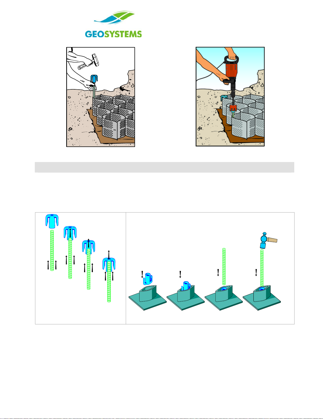
Figure 3 Driving the ATRA Anchor
with a Hammer
Figure 4 Driving the ATRA Anchor
with an Electric Driver
The ATRA® Anchor Installation
Making the ATRA® Anchor
The ATRA Clip easily installs on the end of the ATRA stake to form the ATRA Anchor. The ATRA stake can be a #4
metal rebar or 10-12 mm diameter rod that is cut-to-length to meet the needs of the application. The ATRA Anchor is
made by simply hammering the ATRA Clip onto the ATRA Stake or by hammering the ATRA Stake (metal stakes only)
into the ATRA® Clip as illustrated in Figures 5 and 6. When properly made, the end of the ATRA Stake should be flush
with, to within 3 mm (1/8 in) maximum above the top of the ATRA Clip.
Figure 5 Inserting the ATRA Clip on
the Stake
Figure 6 Inserting the Stake into the ATRA Clip

PRESTO THE ATRA® SYSTEM OVERVIEW
ATRA-OV 1FEB 2009 COPYRIGHT 2009 –PRESTO PRODUCTS CO. PAGE 3OF 5
Using the ATRA® Anchor with Geoweb sections
The ATRA Anchor can directly hold
Geoweb sections down as illustrated in
Figures 7 and 8. The ATRA Anchor is
driven so the arm of the ATRA Clip is
inserted through the Geoweb cell wall slot,
or passes over the Geoweb cell wall
providing direct hold-down as well as
resistance to sliding and uplift forces.
Figure 7 ATRA Anchor
Integrated with Cell-Wall Slots
Figure 8 ATRA Anchor Connected
Over the Cell Wall
Using the ATRA® Anchor with tendoned Geoweb sections
The ATRA Anchor can indirectly hold Geoweb
sections in place when the arm of the clip
passes over a tendon as illustrated in Figure 9.
Greater hold-down can be obtained by passing
the tendon under both arms of the ATRA Clip as
illustrated in Figures 10 and 11.
Greater resistance to sliding forces can be
obtained when the tendon wraps around the clip
and under both arms as illustrated in Figures 12
and 13.
Figure 9 ATRA Anchor and tendon
anchoring
Figure 10 Half Wrap
Figure 11 Full Wrap Figure 12 Double Wrap
Figure 13 Under-Arm Wrap

PRESTO
ATRA-OV 1-FEB-09 COPYRIGHT 2009 –PRESTO PRODUCTS CO. PAGE 4OF 5
THE ATRA® SYSTEM OVERVIEW
The ATRA Anchor is also used at the end of the
tendons as shown in Figure 14 to provide crest and
toe anchorage for Geoweb sections used in slope
and channel protection applications.
Figure 94 ATRA Anchor for Crest and Toe Anchorage
The ATRA® Clip Restraint Pin
Benefits
The ATRA Clip used as a restraint pin, transfers sliding
load forces from the Geoweb cell to the tendon. See
Figure 15.
Cost savings can be realized when using the ATRA Clip.
Securing tendons to other mechanisms, such as straight
pins, is difficult. The ATRA Clip arms allow for the rapid
securing of tendons using the Moore Hitch. See Figure
17 for the Moore Hitch illustration.
Figure 15 ATRA Load Transfer Restraint Pin
ATRA® Clip Restraint Pin Installation
1. After the tendons are inserted in the collapsed Geoweb section and the section is expanded, determine the cells
that are the load transfer points by referring to the engineering details. ATRA Clips are to be inserted in these cell
locations.
2. The location on the tendon where the ATRA Clip is to be tied is the point where the tendon intersects the up-slope
cell wall as shown in Figure 15.
3. The ATRA Clip can be attached to the tendon either moving down slope or
up slope.
•If moving up slope, secure the tendon at the bottom of the slope to an
ATRA Anchor before starting. See Figure 14.
•If moving down slope, secure the tendon at the top of the slope to an
ATRA Anchor illustrated in Figure 14 or deadman anchor illustrated in
Figure 17 before starting.
•In both cases, cut the tendon long enough to allow for all the knots.
Leave plenty of extra slack in the tendon for the Moore Hitch to be
used for the load transfer.
4. Use the Moore Hitch as illustrated in Figure 18 to secure the tendon to the
ATRA Clip. Other knots are not acceptable.
Figure 10 Tendon Secured to
Deadman Anchor

PRESTO THE ATRA® SYSTEM OVERVIEW
ATRA-OV 1FEB 2009 COPYRIGHT 2009 –PRESTO PRODUCTS CO. PAGE 5OF 5
Figure 17 The Moore Hitch
5. Place the arm of the ATRA Clip over the tendon and move the clip up or down on the tendon to ensure contact with
the Geoweb cell wall. Once the ATRA Clip is properly positioned, the Moore Hitch should be finished.
6. Move to the next cell along the tendon and repeat the appropriate steps.
Special Construction Technique Using ATRA® Clip Restraint Pins
When slopes are steep or difficult to work on, such as working over a geomembrane, the following procedure is used to
avoid working directly on the steep slope.
•After inserting the tendons through the unexpanded Geoweb section, expand the Geoweb section at the top of
the slope embankment or other flat area.
•Attach all ATRA Clip Restraint Pins to the tendons using the Moore Hitch in the proper cells to make a pre-
assembled section.
•Maintain a sufficient amount of tendon length for the top-of-slope anchoring method.
•Collapse the pre-assembled Geoweb section with the tendons and ATRA Clip Restraint Pins.
•Move the pre-assembled Geoweb section into its position at the top of the slope and secure the up-slope end
with the appropriate anchoring system.
•Expand the pre-assembled Geoweb section down the slope and secure the down-slope end with the
appropriate anchoring system.
•Prior to the infilling process, visually inspect ATRA Clip Restraint Pins to ensure they have maintained their
position on the tendon.
NOTE: ATRA® is a registered trademark of Presto Products Company. The ATRA® Clip is patented.
This manual suits for next models
1
Table of contents


