Presto ECOA AL Series Setup guide

Presto AX, AXR, AXS,
AXT & AT Series
ECOA AL Series
Scissor Lifts
Installation, Operation
and Service Manual
Model Number ___________________
Serial # _________________________
Date placed in service _____________
IMPORTANT: READ CAREFULLY
BEFORE INSTALLING OR OPERATING LIFT
Part orders are subject to a $50 minimum charge.
March 2020

Page 2 Presto-ECOA Lifts AX, AXR, AXS & AT Series and AL Series
NOTICE
The air actuated tilter is not shown in this manual. But, the air
bag(s) ttings, connections and controls are very similar to the
components used on air actuated lifts. For additional detail
or related questions please contact the Presto-ECOA Service
Department or Parts Department at 800-343-9322.
This manual was current at the time of printing. To obtain the latest, most updated version,
please contact Presto-ECOA Lifts Customer Service Department or go to our website:
www.PrestoLifts.com where you will nd a complete list of current owner’s manuals to print.
This label (part # 10095524)
is required by California law.
For more information visit
www.65Warnings.ca.gov.
This label (part # 10095524)
is required by California law.
For more information visit
www.P65Warnings.ca.gov.

Presto-ECOA Lifts AX, AXR, AXS & AT Series and AL Series Page 3
CONTENTS
SECTION 1: Introduction ............................................................................................................. 4
Responsibility of Owners and Users ....................................................................................... 5
SECTION 2: Safety ..................................................................................................................... 6
SECTION 3: Installation ............................................................................................................... 8
A. Inspection .......................................................................................................................... 8
B. Installing ............................................................................................................................. 8
C. Pneumatics......................................................................................................................... 9
D. Testing the Lift with No Load .............................................................................................. 9
SECTION 4: Operation .............................................................................................................. 10
A. Method of Operation........................................................................................................ 10
B. Operation Procedures ...................................................................................................... 10
SECTION 5: Maintenance ...........................................................................................................11
A. Safety Chocks ...................................................................................................................11
B. Routine Inspection and Maintenance .............................................................................. 12
C. Troubleshooting Maintenance ........................................................................................ 12
D. Removal and Installation of Air Stroke Actuator ............................................................... 12
E. Removal and Installation of Hand/Foot Control................................................................ 13
SECTION 6: Turntable ............................................................................................................... 14
SECTION 7: Pneumatic Positioning Lock .................................................................................. 14
RESTOCKING POLICY............................................................................................................... 22
ORDERING REPLACEMENT PARTS......................................................................................... 23
WARRANTY ................................................................................................................................ 24
LIST OF FIGURES:
Figure 1. Lagging down lift ........................................................................................................... 9
Figure 2. Maintenance Chocks................................................................................................... 10
Figure 3. Pneumatic Connections ...............................................................................................11
Figure 4. Pneumatic Connections with Lock .............................................................................. 14
Figure 5. Pneumatic Components.............................................................................................. 15
Figure 6. Pneumatic Components with Turntable....................................................................... 16
Figure 8. Mechanical Components............................................................................................. 18
Figure 9. Pneumatic Schematic, AX / AT.................................................................................... 19
Figure 10. Labels and Locations ................................................................................................. 20
Figure 11. General Description AL Series.................................................................................... 21

Page 4 Presto-ECOA Lifts AX, AXR, AXS & AT Series and AL Series
S E C T I O N 1
INTRODUCTION
This manual attempts to provide all of the information necessary for the safe and proper installation,
operation and maintenance of AX, AXR, AXS, AXT, AT and ECOA AL Scissors Lifts.
It is important that this manual be read by all personnel involved with the installation, maintenance or
operation of the scissor lift. If the manual does not address an application, call your distributor or Presto-
ECOA Lifts for assistance. Additional manuals are available upon request at www.PrestoLifts.com.
The scissor lift has a nameplate that provides the load capacity rating, serial number and model
identication. Please refer to these numbers when ordering parts or requesting further information.
The AX, AXR, AXS, AXT, AT and ECOAAL Scissors Lifts are designed for lifting, lowering and positioning
a wide variety of loads. WHERE UNIQUE SITUATIONS ARISE, THAT ARE NOT COVERED IN THIS
MANUAL, CALL YOUR DISTRIBUTOR OR Presto-ECOA LIFTS FOR INSTRUCTIONS.
The AX, AXR, AXS, AXT, AT and ECOA AL Scissors Lifts are designed for in-plant/non-hazardous
location use only.

Presto-ECOA Lifts AX, AXR, AXS & AT Series and AL Series Page 5
Responsibility of Owners and Users
Inspection and Maintenance
The device shall be inspected and maintained in proper working order in accordance with Presto-
ECOA owner’s manual.
Removal from Service
Any device not in safe operating condition such as, but not limited to, excessive leakage, missing
rollers, pins, or fasteners, any bent or cracked structural members, cut or frayed electric, hydraulic,
or pneumatic lines, damaged or malfunctioning controls or safety devices, etc. shall be removed
from service until it is repaired to the original manufacturer’s standards.
Repairs
All repairs shall be made by qualied personnel in conformance with Presto's instructions.
Operators
Only trained personnel and authorized personnel shall be permitted to operate these lifts.
Before Operation
Before using the device, the operator shall have:
• Read and/or had explained, and understood, the manufacturer’s operating instructions and
safety rules.
• Inspected the device for proper operation and condition. Any suspect item shall be carefully
examined and a determination made by a qualied person as to whether it constitutes a hazard.
All items not in conformance with Presto’s specication shall be corrected before further use
of these lifts.
During Operation
The device shall only be used in accordance with this owner’s manual.
• Do not overload.
• Ensure that all safety devices are operational and in place.
Modications or Alterations
Modications or alterations to any Presto-ECOA industrial positioning equipment shall be made only
with written permission from Presto.

Page 6 Presto-ECOA Lifts AX, AXR, AXS & AT Series and AL Series
SAFETY ALERT SYMBOLS AND SIGNAL WORDS
The safety of all persons operating, maintaining, repairing, or in the vicinity of this equipment is of paramount concern. This is
a powerful machine with moving parts, and is capable of causing personal injury if proper precautions are not taken. Therefore,
throughout this manual, certain hazards have been identied which may occur in the use of the machine, and there are appropriate
instructions or precautions which should be taken to avoid these hazards. In some cases, there are consequences which
may occur if instructions or precautions are not followed. Below are the symbols and signal words along with their denitions
referenced from ANSI Z535.4 - Product Safety Signs and Labels.
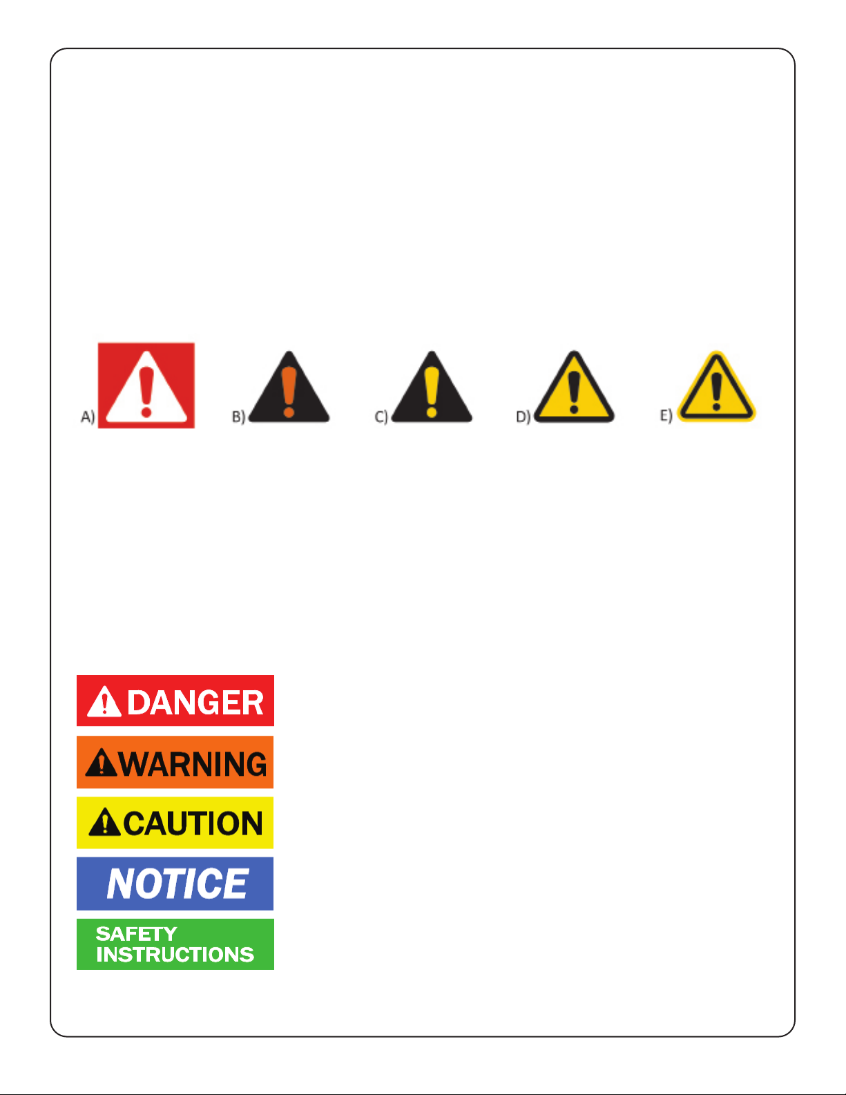
4.11 Safety Alert Symbols: A symbol that indicates a hazard. It is composed of an equilateral triangle surrounding
an exclamation mark. The safety alert symbol is only used on hazard alerting signs. It is not used on safety notice and safety
instructions signs.
4.14 Signal Words: The words used in the signal word panel. The signal words for hazard alerting signs are “DANGER,”
“WARNING,” and “CAUTION.” Safety notice signs use the signal word “NOTICE.” Safety instruction signs use signal words that
are specic to the situation.
DANGER indicates a hazardous situation which, if not avoided, will result
in death or serious injury.
WARNING indicates a hazardous situation which, if not avoided, could
result in death or serious injury.
CAUTION indicates a hazardous situation which, if not avoided, could
result in minor or moderate injury.
NOTICE is used to address practices not related to physical injury.
SAFETY INSTRUCTIONS (or equivalent) signs indicate specic safety-
related instructions or procedures.
NOTE: DANGER, WARNING or CAUTION should not be considered for property damage accidents unless personal injury risk
appropriate to these levels is involved.
A): for use with DANGER signal word; (safety white triangle, safety red exclamation mark, safety red background)
B): for use with WARNING signal word; (safety black triangle, safety orange exclamation mark)
C): for use with CAUTION signal word; (safety black triangle, safety yellow exclamation mark)
D) and E): for use with DANGER, WARNING, or CAUTION signal word; (D: is a safety yellow triangle with a
black border and safety black exclamation mark; E: is a safety yellow triangle with a safety black exclamation mark and a
safety yellow border around a safety black band)
NOTE: D and E are provided to allow for consistency with certain ISO standards such as ISO 3864-1 and ISO 3864-2.

Presto-ECOA Lifts AX, AXR, AXS & AT Series and AL Series Page 7
WARNING!
• Do not perform any repair work on a lift with a load on the platform or with the table in a raised position.
• All personnel must stand clear of the lift when the lift is in motion.
• Do not put hands or feet under lift table.
• Do not perform any repair or maintenance work with the lift in an open position without securing it
rst with proper maintenance devices.
• Do not stand, sit or climb on the lift at any time.
• Do not use the lift on soft, uneven or unstable surfaces.
• Do not exceed the load capacity rating on the data plate.
• Do not place a load on a moving lift.
• Do not exceed load capacity.
• Place a load in the center of the lift and be sure that the load is secured properly.
S E C T I O N 2
SAFETY
The safety of all persons installing, using, servicing, or working near the unit is of paramount concern to
Presto-ECOA Lifts. The lift is a powerful machine with moving parts, and is capable of causing personal
injury if proper precautions are not taken. Therefore, throughout this manual, Presto-ECOA Lifts have
identied certain hazards, which may occur in the use of the unit, and provided appropriate instructions
or precautions that should be taken to avoid these hazards. In some cases, Presto-ECOA Lifts has also
pointed out the consequences that may occur if Presto-ECOA Lifts instructions or precautions are not
followed. Presto-ECOA Lifts use the following nationally recognized system for identifying the severity
of the hazards associated with its products:
DANGER – Immediate hazard that will result in severe personal injury or death.
WARNING – Hazard or unsafe practice, that could result in severe personal injury or death.
CAUTION – Hazard or unsafe practice, that could result in minor personal injury or property
damage.
In the interest of safety, please read the entire manual carefully. You must understand the material
in this manual before you install, use, or service the unit. If you have any question about any of
the instructions in this manual, please contact Presto-ECOA Lifts at 1-800-343-9322.

Page 8 Presto-ECOA Lifts AX, AXR, AXS & AT Series and AL Series
S E C T I O N 3
INSTALLATION
A. INSPECTION
Upon receipt of the AX/AXR/AXS/AXT/AT and AL Scissor Lift, inspect the equipment completely to
determine if there is any damage that occurred during shipment and that the lift is complete. Do not
use the lift if there appears to be any damage. Check the following with the lift in the collapsed position:
1. Check for signs of damage, especially to the Airstroke Actuator™ and pneumatic components.
2. Check all connections and nuts/bolts for tightness.
3. Check base frames for atness and for bent or damaged metal parts.
CAUTION!
Do not operate the lift before performing the installation procedures specied in section
B. Severe damage to the lift may occur.
B. INSTALLING
Floor Installation
a) Make sure that the oor in the installation area is at, stable, relatively smooth and free
from dirt, obstacles or surface defects.
b) Place the lift in the exact operating position.
CAUTION!
When moving the lift never attempt to pick it up by the platform. The lift should be picked
up only by the base frame only. The use of a spreader strap/sling is suggested. If the
lift has lifting eyebolts, attach a chain spreader and raise the lift from a center position.
Be sure that the eye bolts are secured in place with locking nuts prior to lifting.
c) Make sure that the complete base of the lift is in contact with the oor. In order to provide com-
plete contact with the oor, the base may be shimmed or grouted.
CAUTION!
Do not spot shim. The complete base must be in contact with the oor or shims.
NOTICE
Machine base lag anchors need to be sized for a minimum of 5000# pull-
out force for each lag.
d) The lift frame must be anchored to the oor using four 3/4" diameter bolts, washers and nuts.
e) Locate and lag down hand control stand or foot control so as to provide easy access. Do not
obstruct the operator's work area. Make pneumatic connections according to the information con-
tained in Section 3C.
CAUTION!
Not lagging the lift base will result in structural damage to the lift.
Pit Mounted Installation
a) Build pit to standard pit dimension as outlined in gure 2, paying careful attention
to raceway, clearance and height requirements.
b) The remaining steps are the same as required for oor installation. See section 3B.
WARNING!
Do not install lifts in pits unless they have an approved bevel edge top and fully exhausting
pneumatic circuit.

Presto-ECOA Lifts AX, AXR, AXS & AT Series and AL Series Page 9
WARNING!
The lift is equipped with a tamperproof pressure regulator. The regulator has been factory
preset and no attempt should be made to alter the setting. Resetting of the regulator or
replacement with a component not supplied by Presto-ECOA Lifts will void warranty and
could result in serious bodily injury.
D. TESTING THE LIFT WITH NO LOAD
1. Before testing the lift, clear the area of any loose material. Be sure the lift has no obstruction
above it or on any side. Using the controls provided, briey oper- ate the lift (5-10 seconds). If the lift
begins to rise and functions properly, continue to the full upright position.
CAUTION!
If the lift does not rise immediately, or there is any operational problem, stop it immediately.
Refer to the troubleshooting section and correct the problem before continuing.
2. After raising the lift completely, lower the lift completely. It should lower slowly and smoothly. If satised
with the lift's operation, raise and lower the lift and stop at different levels in order to familiarize yourself
with the lift’s operation.
C. PNEUMATICS
AX/AXR/AXS/AT and AL Scissor Lifts are designed
for normal factory environments. Consult the
distributor for unusual applications. If your lift is
equipped with a turntable positioning lock, refer to
Section 6B.
CAUTION!
All pneumatic connections should
be performed by qualied authorized
service personnel.
1. The lift requires a minimum of 80 PSI, 15 CFM,
and clean dry air to function correctly.
2. Be certain that supply line is turned off and
residual air has been purged from the line.
3. The lift is shipped with the control line attached
to the control valve (B) and detached from the lift
base. Route the control line safely to the base and
make the connection (C).
4. Connect the supply line to the open port of the
control valve (A).
5. Open the air supply and check the entire circuit
for leaks. Secure as needed. See Fig. 3.
Figure 1:
Lagging down lift

Page 10 Presto-ECOA Lifts AX, AXR, AXS & AT Series and AL Series
S E C T I O N 4
OPERATION
A. METHOD OF OPERATION
The control valve controls the ow of air to the Air
Stroke Actuator™. As the actuator is pressurized,
the scissor legs are forced apart causing the
tabletop to rise. As air is released from the bag,
the legs collapse and the top is lowered. A factory
preset ow control ensures a smooth descent at a
controlled speed.
CAUTION!
Do not maintain the control valve in the
open position if the lift does not move
or it has reached its up or down limits.
Damage to the pneumatic system may
result.
Figure 2: Maintenance chocks
B
A
B. OPERATION PROCEDURES
In order to operate the lift, follow these operating procedures:
WARNING!
a) Load the lift only in the collapsed position.
b) Do not stand, sit or climb onto the lift.
c) If the lift fails to move or exhibits strange movement or sound, stop immediately. Do not
operate the lift until it has been checked and repaired.
d) Do not load or unload a moving lift.
e) Obey all warning labels.
1. Read and understand all the instructions before operating. If the lift has modications or
accessories, read and understand their functions.
2. Load the lift correctly. Refer to the attached nameplate for load capacity information.
a) Load the lift only in the fully lowered position.
b) Do not load or unload the lift while it is moving.
c) Do not exceed the maximum rated load (note that load capacity is reduced due to side or end
loading).
d) Place load in the center of table.
e) If the load is unstable or may become unstable, fasten it into position.
3. Operate the lift.
a) To raise the lift, activate the hand control valve to the “up” position. Hold the valve open until the lift
reaches the desired position or the lift reaches its full extension. The valve is spring-loaded and will
return to center (closed) when the lever is released.
b) To lower the lift, activate the hand control valve to the down position. Hold the valve open until the
lift descends to the desired height or the lift reaches its fully lowered position. Move the valve briey to
the up position to stop downward movement.
4. Wait until the lift has come to a complete stop before unloading the lift.
5. Stand clear of the lift when operating in order to avoid injury.

Presto-ECOA Lifts AX, AXR, AXS & AT Series and AL Series Page 11
S E C T I O N 5
MAINTENANCE
Generally, the AX/AXR/AXS/AXT/AT and AL Series of pneumatic scissor lifts will require little main-
tenance. However, routine maintenance and inspection will minimize cost of repairs and hazardous
conditions.
WARNING!
Never go under or service lift with a load on the table or with the scissor mechanism
loaded. If possible, service the lift in a down position.
WARNING!
If the pneumatic system requires repairs, shut off and lock out the air supply. Purge the
system of any pressure before beginning any repairs.
A. MAINTENANCE CHOCKS
The AX, AXR, AXS, AXT, AT Series and the AL Scissors Lifts are designed to be maintained and serviced
in a raised position. Maintenance chocks are provided for locking the lift in a raised position. Refer to
Figure 2.
1. Chock Installation
a) Completely remove any load from the lift platform.
b) Raise the lift to its full height.
c) Slip the maintenance chock (A) in place and insert the locking pin (B).
d) Lower the lift until the leg roller comes in contact with the maintenance chock.
e) Check that the maintenance chock is securely in place.
f) Release all air pressure from the lift. The chock is now supporting the lift.
2. Chock Removal
a) Raise the lift to its full height.
b) Remove the locking pin (B) and the maintenance chock (A).
c) Lower the lift.
Figure 3: Pneumatic connections

Page 12 Presto-ECOA Lifts AX, AXR, AXS & AT Series and AL Series
B. ROUTINE INSPECTION AND MAINTENANCE
All routine inspection maintenance should be performed on a monthly basis.
WARNING!
Maintenance chock and pin must be installed on the lift while maintenance is being per-
formed. Contact Presto-ECOA Lifts for the recommended parts, if yellow maintenance
chock is not available.
1. With the lift unloaded and its fully raised position, check the pneumatic system for leaks.
a) Check all ttings, lines and components for escaping air.
b) In addition to listening for an audible hissing, perform a soap bubble test.
c) If a leak exists, repair immediately.
2. Inspect the following:
a. Check snap ring and shield on rollers. Replace if damaged.
3. Check Air Stroke Actuator™ for any signs of wear, chang, nicks, splits, etc. Replace as specied
in Section 5 (D).
4. Check rollers for signs of wear. Replace if damaged. Clear roller track of any debris.
Refer to Figure 8.
5. Check roller snap ring and shield. Replace if damaged. Refer to Figure 8.
6. Tighten all visible nuts and bolts.
7. Bearings on all lifts are permanently lubricated and do not require servicing.
8. Check all lag anchors to make sure they are tight.
C. TROUBLESHOOTING MAINTENANCE
All servicing should be done by qualied personnel who have read and understand all of the informa-
tion provided in the Operating, Installation and Maintenance sections of this manual.
LIFT MOVING SLOWLY OR NOT AT ALL
1. Check for obstructions.
2. Check for incoming air supply. Both PSI and CFM.
3. Check circuit for air leaks, loose connection, damaged hose, etc. Listen for air escaping.
4. Is lift overloaded? Check capacity.
5. Check control valve for sticking or jamming, repair or replace.
D. REMOVAL AND INSTALLATION OF AIR STROKE ACTUATOR™
1. Chock the lift as specied and be sure air supply is locked out.
2. Remove the braided hose (20) and brass nipple (19).
3. Remove the four 3/8-16 nuts (25) with a 9/16 deep socket. The Actuator will collapse as the last nut
is removed.
4. Remove the four 3/8-16 hex head bolts (22) and washers (21). The Actuator will become free of the
lift and may be removed.

Presto-ECOA Lifts AX, AXR, AXS & AT Series and AL Series Page 13
5. Remove the four 3/8-16 (26) hex head bolts and lock washers (23) holding the plate (28) to
the Actuator.
6. Unscrew the elbow (6).
7. Finally remove the four studs (24) from the Actuator end plates.
8. Installation is the reverse of removal. Be sure to use a Teon sealant on all pneumatic
connections. Pump must be replaced.
E. REMOVAL AND INSTALLATION OF
HAND/FOOT CONTROL
1. Chock the lift as specied and be sure air supply is locked out.
2. Disconnect hose (8) and supply line.
3. Remove [2] plugs (5), [1] mufer (4), elbow (6).
4. Remove (2) securing nuts/bolts and remove valve from stand if a hand valve.
5. Installation is the reverse of removal. Be sure to use Teon sealant on all NPT pneumatic
connections.

Page 14 Presto-ECOA Lifts AX, AXR, AXS & AT Series and AL Series
S E C T I O N 6
TURNTABLE
If your lift is equipped with a rotating turntable, the following operational/ maintenance procedures apply.
A. INSPECTION
As with the basic scissor lift, inspect the unit to be sure no damage has occurred in shipment and that
the unit is complete.
1. Rotate the turntable by hand to be sure the table rotates freely without binding or unusual
sounds.
2. Inspect for loose/ damaged connections and nuts/bolts.
Figure 4: Pneumatic connections with lock
S E C T I O N 7
PNEUMATIC ROTATIONAL POSITIONING LOCK
B. INSTALLATION (IF EQUIPPED) OF PNEUMATIC POSITIONING LOCK
The initial pneumatic connections differ from a standard lift and are specied below. All other installation,
safety and use instructions should be observed. Refer to schematic Fig. 8 and Fig. 9.
1. Connect incoming air supply to inlet (A).
2. Connect supply line (B).
3. Connect control line (C) lifting.
4. Connect control line (D) lock.
Positioning Lock:
The lock is designed for holding the turntable in place; it is not designed to stop or brake a rotating load.
1. Manually rotate the turntable to the desired position.
2. With the turntable at rest, activate the lock control valve to the “on” position. This will lock the
table in place.
3. Moving the control valve to "off" will release the lock and allow the turntable to rotate.

Presto-ECOA Lifts AX, AXR, AXS & AT Series and AL Series Page 15
Pneumatic Components Replacement List
(Refer to Figure 5)
Location Description AX10 AX20 AX40
1Pneumatic Valve 1 1 1
2 Nameplate 1 1 1
3 Screw 2 2 2
4Mufer 2 2 2
5Plug-Oil Tank 2 2 2
6 Elbow, Street 3 3 4
7 Fitting 2 2 2
8Hose 1 1 1
9 Elbow 1 1 1
10 Nipple, Brass 1 1 1
11 Regulator 1 1 1
12 Screw 2 2 2
13 Nut, Machine 2 2 2
Call Parts Department with model and serial number to receive a quotation.
Figure 5: Pneumatic components
Location Description AX10 AX20 AX40
14, 17 Nipple, Brass 1 1 1
15 Reducer 2 2 3
16 Quick Exhaust 1 1 1
18 Tee Female - - 1
19 3" Brass Nipple - 1 2
20 SS Hose Assy. 1 1 2
23 Washer, Lock 8 8 16
24 Screw 4 4 8
25 Nut, Self Lock 4 4 8
26 Screw 3/8" - 16x 8 8 16
27 Airstroke Actuator - 1 2
27 Airstroke Actuator 1 - -
28 Sub Plate Air 1 1 2

Page 16 Presto-ECOA Lifts AX, AXR, AXS & AT Series and AL Series
Figure 6: Pneumatic components with turntable

Presto-ECOA Lifts AX, AXR, AXS & AT Series and AL Series Page 17
Turntable Positioning Lock Components Replacement List
(Refer to Figure 6)
Loca-
tion
Description AXR10 AXR20 ARX40
1Pneumatic Valve 1 1 1
2 Nameplate 1 1 1
3 Screw 2 2 2
4Mufer 2 2 2
5 Elbow, Street 3 3 4
6 Fitting 2 2 2
7Hose 1 1 1
8 Plug 2 2 2
10 Hose 1 1 1
11 Regulator 1 1 1
12 Screw 2 2 2
13 Nut, Machine 2 2 2
14 Bulkhead Fitting 2 2 2
15 Bulkhead Fitting 4 4 4
16 Bulkhead Fitting 2 2 2
17 Brass Nipple 3/8" 1 1 1
18 Reducer 2 2 3
19 Quick Exhaust 1 1 1
20 Female Fitting 3/8" 1 1 2
21 Tee Male 1 1 1
22 Tubing 2 2 2
23 Elbow, 90 degree 2 2 2
24 Nut, 5/8" 2 2 2
25 Washer, Lock 2 2 2
26 Air Positioner 2 2 2
27 Pad Positioning 2 2 2
28 Screw 2 2 2
29 SS Hose Assembly 1 1 1
30 Valve, Hand 2 Pts. 1 1 1
31 Nameplate 1 1 1
32 Brass Nipple 1/4" 2 2 2
33 Female Tee 1/4" 1 1 1
35 El-Female 1 1 1
36 Brass Nipple 2 2 2
Call Parts Department with model and serial number to receive a quotation.

Page 18 Presto-ECOA Lifts AX, AXR, AXS & AT Series and AL Series
Figure 8: Mechanical components
Mechanical Components Replacement List
(Refer to Figure 8)
Location Description AXR10 AXR20 ARX40
1Pin Retain Assembly 4 4 4
2Screw 1/4" 4 4 4
3Washer, Lock 4 4 4
4Ring, External 4 4 4
5 Spacer 2 2 2
6 Retaining Ring 2 2 2
7 Roller 4 4 4
8Washer, 1" ID 4 4 4
9Rings, Lock 1 1 1
10 Bearing, Radial 1 1 1
11 Bronz, Center 1 1 1
12 Screw, Shoulder 1 1 1
Call Parts Department with model and serial number to receive a quotation.

Presto-ECOA Lifts AX, AXR, AXS & AT Series and AL Series Page 19
Figure 9: Pneumatic schematic AX / AT

Page 20 Presto-ECOA Lifts AX, AXR, AXS & AT Series and AL Series
Figure 10. Labels and Locations
This manual suits for next models
11
Table of contents
Other Presto Scissor Lift manuals
Popular Scissor Lift manuals by other brands

John Bean
John Bean Spacesaver 9000 Series Installation and operation manual

Skyjack
Skyjack SJ6826 RT Operation manual

Peak
Peak AMGO PX12 Installation and service manual

Presto Lifts
Presto Lifts DBP Series Installation, operation and service manual

Sinoboom
Sinoboom GTJZ0612E Maintenance manual

POP UP
POP UP MiPOD 1000 Assembly guide