PRETUL HIDR-1/2x24P User manual
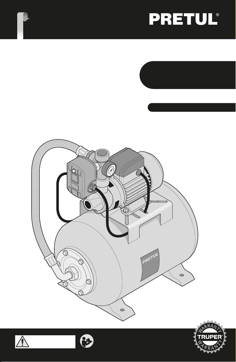
Manual
Hydro
Pneumatic
Pressure
Boosting System
Codes Models
20183
20184
Applies for:
HIDR-1/2x24P
HIDR-1/2x50P
CAUTION
20183
6.3 gal 20184
Tank Capacity
13.2 gal
ENGLISH
ESPAÑOL
Read the user’s manual thoroughly
before operating this tool.
HIDR-1/2x24P
HIDR-1/2x50P
2
Technical Specifications
Power Requirements
General Power Tools Safety Warnings
Safety Warnings for Water Pumps
Parts
Installation
Pressure Switch
Start Up
Maintenance
Troubleshooting
Notes
Authorized Service Centers
Warranty Policy
3
3
4
5
6
7
8
8
9
9
10
11
12
ENGLISH
Contents
CAUTION
Keep this manual for future references.
The illustrations in this manual are for reference
only. They might be different from the real tool.
To gain the best performance of
the tool, prolong the duty life,
make the Warranty valid if
necessary, and to avoid hazards
of fatal injuries please read and
understand this Manual before
using the tool.
26.2 ft
11 gal/min
Power Cord Grips used in this product: Type “Y”.
Tool Build Quality: Basic insulation
Thermal insulation on motor winding: Class F
1” x 1”
Inlet and Outlet Diameter
Maximum Height (Maximum value of
total manometer height)
30 min work x 20 min rest. Maximum 6 hours
18 AWG 18 AWG
Conductors
Duty Cycle
Class I
Insulation
65.6 ft
Maximum Suction Depth
Tank Capacity 6.3 gal 13.2 gal
Maximum Flow
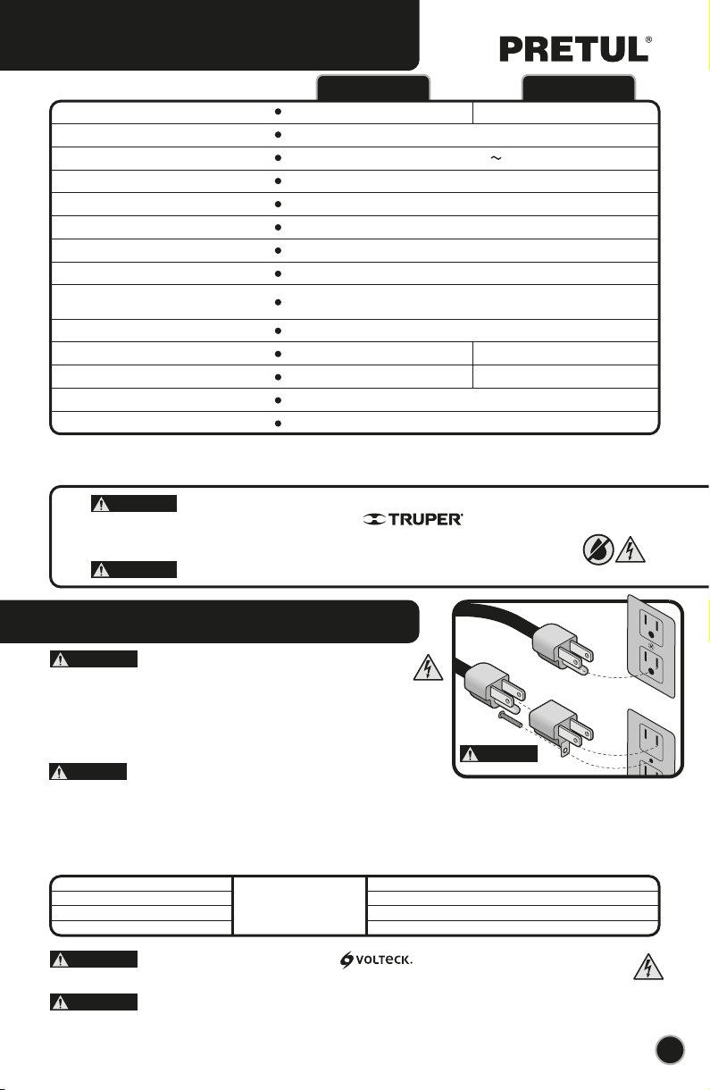
3
20183 20184
3.5 A
60 Hz
Hydro Pneumatic Pressure Boosting System
Code
Description
Voltage
Frequency
3450 RPM
Speed
Current
Technical Specifications
Power Requirements
127 V
HIDR-1/2x24P HIDR-1/2x50P
CAUTION
To prevent electric shock, the tool shall be grounded while
in use. • Connect the plug into a correctly grounded outlet as shown in
example A. Not all the outlets are properly grounded. If in doubt, verify with a
qualified electrician. • If the outlet where you will connect the tool has two
poles (2 orifices). UNDER ANY CIRCUMSTANCE, DO NOT REMOVE OR
ALTER THE PLUG’S GROUND CONNECTOR. Use a temporary adaptor as
shown in example Band always connect the ground conductor lug as shown.
When using an extension cable, verify the gauge is enough
for the power that the tool needs. A lower gauge cable will cause voltage drop
in the line, resulting in power loss and the motor will overheat. The following table shows the right size to use depending on cable’s
length and the ampere capability shown in the tool’s nameplate. When in doubt use the next higher gauge.
WARNING
All the cabling, power connections and the ground connection of the system shall
comply with the OFFICIAL MEXICAN STANDARD NOM - 001 SEDE-2012, ELECTRICAL INSTALLATIONS
(UTILIZATION) or with the local codes or regulations. Use the services of a qualified electrician.
WARNING
WARNING
ENGLISH
A
B
CAUTION
WARNING
WARNING Avoid the risk of electric shock or severe injury. When the power cable gets damaged
it should only be replaced by the manufacturer or at a Authorized Service Center.
The build quality of the electric insulation is altered if spills or liquid gets into the tool while in use.
Do not expose to rain, liquids and/or dampness.
Before gaining access to the terminals all power sources should be disconnected.
When using power tools outdoors use a grounded extension cable labeled “Outdoors
Use”. These extension cables are specially manufactured for outdoors use and reduce the risk of electric shock.
from 0 A and up to 10 A
from 10 A and up to 13 A
from 13 A and up to 15 A
from 15 A and up to 20 A
18 AWG(*)
16 AWG
14 AWG
8 AWG
16 AWG
14 AWG
12 AWG
6 AWG
3 (one grounded)
from 6’ to 49’ | higher than 49’
Ampere
Capacity Number of
Conductors Extension gauge
4ENGLISH
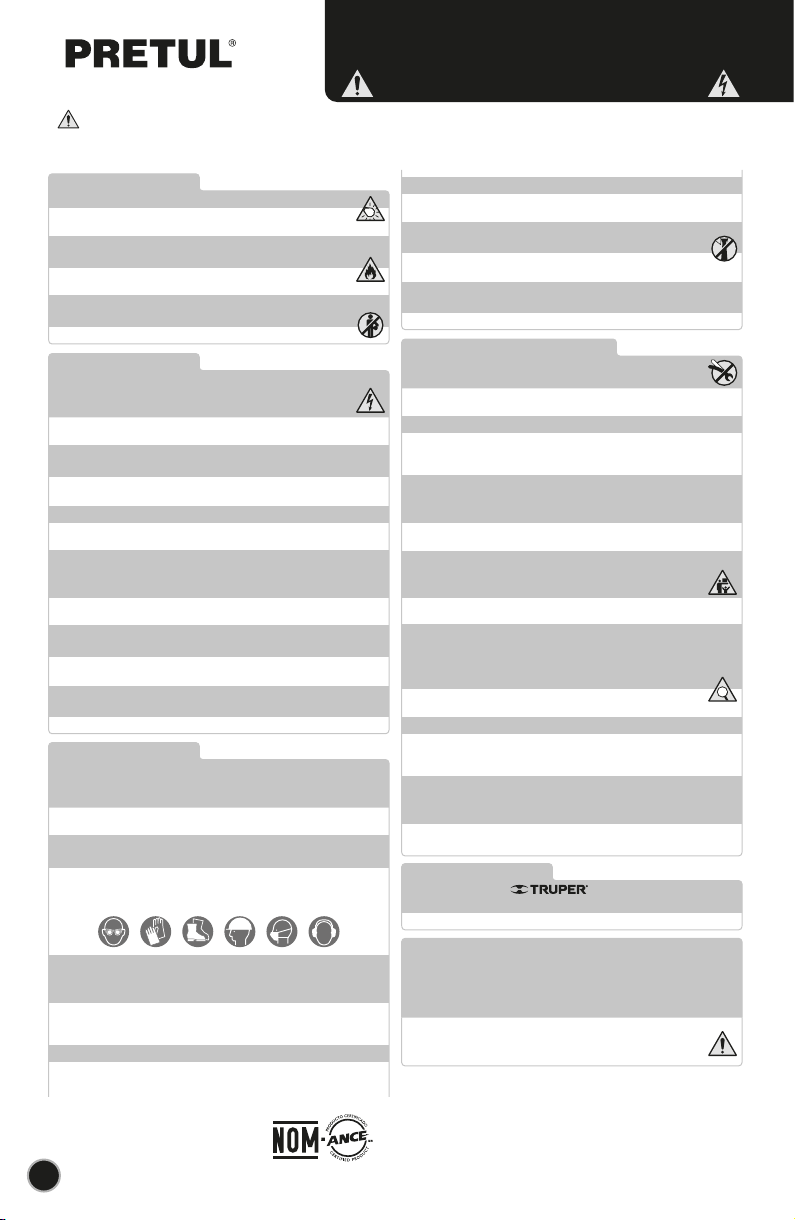
General Power Tools
Safety Warnings
Work area
Keep your work area clean, and well lit.
Cluttered and dark areas may cause accidents.
Never use the tool in explosive atmospheres, such as in the
presence of flammable liquids, gases or dust.
Sparks generated by power tools may ignite the flammable material.
Keep children and bystanders at a safe distance while operating
the tool.
Distractions may cause loosing control.
Electrical Safety
The tool plug must match the power outlet. Never modify
the plug in any way. Do not use any adapter plugs with
grounded power tools.
Modified plugs and different power outlets increase the risk of electric shock.
Avoid body contact with grounded surfaces, such as pipes,
radiators, electric ranges and refrigerators.
The risk of electric shock increases if your body is grounded.
Do not expose the tool to rain or wet conditions.
Water entering into the tool increases the risk of electric shock.
Do not force the cord. Never use the cord to carry, lift or unplug
the tool. Keep the cord away from heat, oil, sharp edges or
moving parts.
Damaged or entangled cords increase the risk of electric shock.
When operating a tool outdoors, use an extension cord suitable
for outdoor use.
Using an adequate outdoor extension cord reduces the risk of electric shock.
If operating the tool in a damp location cannot be avoided, use
a ground fault circuit interrupter (GFCI) protected supply.
Using a GFCI reduces the risk of electric shock.
Personal safety
Stay alert, watch what you are doing and use common sense
when operating a tool. Do not use a power tool while you are
tired or under the influence of drugs, alcohol or medication.
A moment of distraction while operating the tool may result in personal injury.
Use personal protective equipment. Always wear eye
protection.
Protective equipment such as safety glasses, anti-dust mask, non-skid shoes,
hard hats and hearing protection used in the right conditions significantly
reduce personal injury.
Prevent unintentional starting up. Ensure the switch is in the
“OFF” position before connecting into the power source and /
or battery as well as when carrying the tool.
Transporting power tools with the finger on the switch or connecting power
tools with the switch in the “ON” position may cause accidents.
Remove any wrench or vice before turning the power tool on.
Wrenches or vices left attached to rotating parts of the tool may result in personal
injury.
Do not overreach. Keep proper footing and balance at all times.
This enables a better control on the tool during unexpected situations.
Dress properly. Do not wear loose clothing or jewelry. Keep
hair, clothes and gloves away from the moving parts.
Loose clothes or long hair may get caught in moving parts.
If you have dust extraction and recollection devices connected
onto the tool, inspect their connections and use them correctly.
Using these devices reduce dust-related risks.
Power Tools Use and Care
Do not force the tool. Use the adequate tool for your
application.
The correct tool delivers a better and safer job at the rate for which it was designed.
Do not use the tool if the switch is not working properly.
Any power tool that cannot be turned ON or OFF is dangerous and should be
repaired before operating.
Disconnect the tool from the power source and / or battery
before making any adjustments, changing accessories or
storing.
These measures reduce the risk of accidentally starting the tool.
Store tools out of the reach of children. Do not allow persons
that are not familiar with the tool or its instructions to
operate the tool.
Power tools are dangerous in the hands of untrained users.
Service the tool. Check the mobile parts are not misaligned or
stuck. There should not be broken parts or other conditions that
may affect its operation. Repair any damage before using the
tool.
Most accidents are caused due to poor maintenance to the tools.
Keep the cutting accessories sharp and clean.
Cutting accessories in good working conditions are less likely to bind and are
easier to control.
Use the tool, components and accessories in accordance with
these instructions and the projected way to use it for the type of
tool when in adequate working conditions.
Using the tool for applications different from those it was designed for, could
result in a hazardous situation.
Service
Repair the tool in a Authorized Service Center
using only identical spare parts.
This will ensure that the safety of the power tool is maintained.
Children or people with reduced physical, sensory or mental
capabilities shall not operate the tool, neither inexperienced
people or without knowledge in the use of the tool, unless
supervised by a person responsible of their safety or if receiving
previous instructions about the tool operation.
Children shall be kept under supervision to double-check they will not play
with the tool. Tight supervision shall be used with children or disabled
persons to prevent from using or being close to any household tool.
WARNING! Read carefully all safety warnings and instructions listed below. Failure to comply with any of
these warnings may result in electric shock, fire and / or severe damage. Save all warnings and instructions for
future references.
This tool is in compliance with
the Official Mexican Standard
(NOM - Norma Oficial Mexicana).

5
• Do not install the device outdoors or
wet areas.
• Do not install the device in areas
where there is danger of explosion or near combustible
liquids or gases.
• Do not aim the water jet against the
device or other electrical components. There is danger of
death due to electric shock.
• Double check the power cable is not
making contact with the water running close to the device.
• Any repairs shall only be carried out in a
Authorized Service Center. Otherwise,
there is danger of being exposed to an electric shock and
voids the Warranty.
• The symbols adhered to the device shall not be removed
nor be covered. All the information about the device that is
not legible shall be replaced immediately.
• Read and obey the operations instructions before
installing and starting the equipment. Any damage caused
by omitting these instructive indications may damage the
equipment and voids the Warranty.
• The pump shall be connected through a residual current
switch designed with a short circuit current not higher than
30 mA.
CAUTION
CAUTION
WARNING
WARNING
• The equipment is a stationary device designed to pump
neutral, clean liquids with no abrasive solids suspended,
with temperature not above 104 °F (104 °F for pumps with
plastic drivers or diffusers). Any other type of use is
inadequate.
• The device is in compliance with the security most
updated requirements only if it is used the way it is
designed. The device can only be used under the
performance restrictions admitted.
• It shall not be used to pump explosives, fuels or
aggressive materials or substances hazardous to health or
sewage water.
• The device is not adequate for commercial or industrial
use.
• The inadequate use or modifications to the device, the
use of the components that are not approved or tested by
the manufacturer may result in unforeseen damage to the
device and the operator and relieves the manufacturer of
legal liability.
Adequate Uses
ENGLISH
Safety Warnings
for Water Pumps
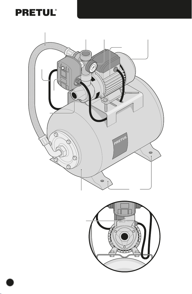
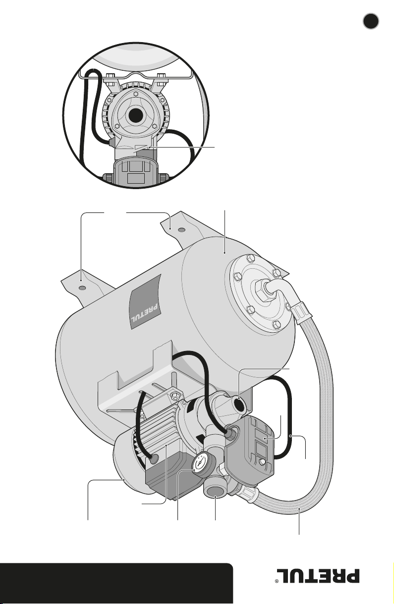
Support to
fix the
equipmentTank
Pressure
Switch
(pressurestat)
Purging
Cap
Water
Outlet
Pump-tank
inter-connection
hose
Closed electric motor
with external ventilation
Water
Input
Power
Cable
Manometer
Peripheral pump
6
Parts
ENGLISH

E
Wrong
Installation
7
Installation
A
C
B
D
E
F
F
• The equipment shall be installed in a dry place, safeguarding from outdoors and
allowing air flow for its correct ventilation (A). Environment temperature shall not
exceed 104 °F.
• Use bolts to fix the equipment to a concrete base to prevent any vibration (B). The
hydro pneumatic equipment shall be installed in horizontal position to assure good
performance.
• The suction line pipes and pressure shall have supports to the wall or floor to
prevent the tension transmission to the hydro pneumatic equipment (C).
• Use care not to damaging the hydro pneumatic equipment and /or pipes by
tightening in excess the joints.
• Seal all the connections with thread sealing tape (Teflon). Leaks cause air flowing out
and obstruct water output.
Set Up
• The suction pipe diameter shall not be lower than the diameter or the water outlet
of the hydro pneumatic equipment. If the suction height exceeds 13 ft, use a pipe with
a smaller diameter.
• The suction pipe shall be totally hermetic. Its end shall be submerged into water at
least half-a meter. It is recommended to install a foot-valve (D). The elbow pipes shall
be 90° towards the water intake of the hydro pneumatic equipment.
• The suction line shall be as short as possible, because the suction capacity lowers
simultaneously with the increase of the line. The suction line shall go up regularly
towards the equipment to prevent air pockets.
If these indications are not followed air and bubbles will
close the flow and interfere with the good performance of the hydro
pneumatic equipment.
Suction Line (input)
CAUTION
• Adapt into the outlet pipe, a gate valve (E) to adjust the
flow and pressure speed required.
• We recommend setting to check valves (F), one between
the entry of the pressurized water and the gate valve and
another one between the water depository or cistern and the
water inlet.
Pressure line (output)
ENGLISH

8
Installation
Pressure Switch
Start Up
• Ask a professional electrician to make the power connection to the power supply. Comply with the corresponding
mandatory rules.
• The fixed installation shall incorporate a device to assure the omni-polar disconnection of the energy feed.
• Assure the electric requirements described in this Instructions and in the hydro equipment nameplate match with the
power supply capacity values.
• The hydro pneumatic has one-phase motor protected against overload using a thermal device (over-current) set in the
winding.
Electric connection
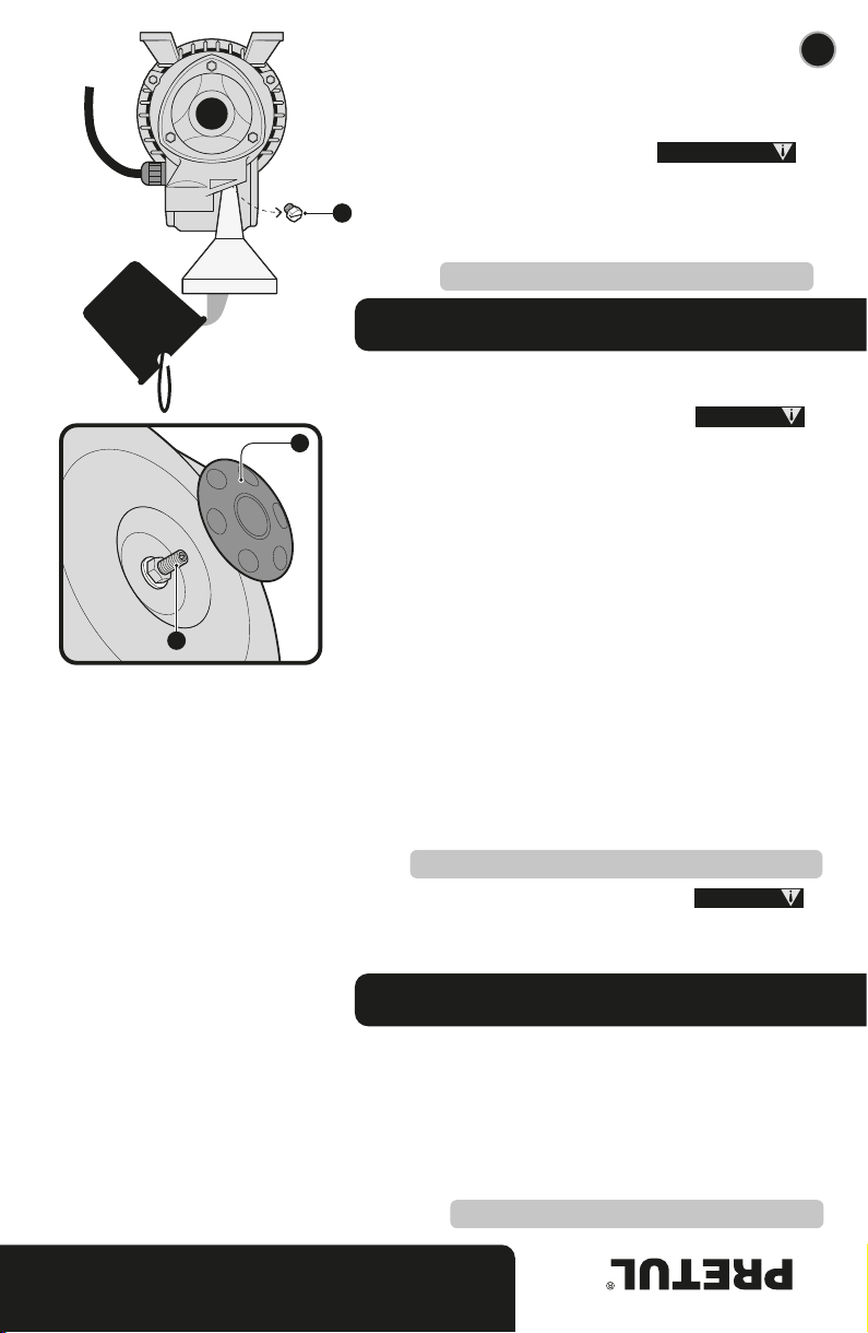
Purge
• The first time you start the hydro pneumatic equipment or after a
long period of inactivity, or when air entered into de system, fill the
pump with clean water before you start it.
• Remove the purge cap (A) and fill-up with water up to the orifice level.
• Screw the cap and start the hydro pneumatic equipment.
Never start the hydro-pneumatic equipment when the
pump is empty. If it happens accidentally, turn off the hydro-pneumatic,
wait until it cools down and then gill the pump using water.
WARNING
ENGLISH
B
• The hydro pneumatic machine is equipped with a pressure switch (pressurestat) that turns on the motor when the tank
pressure is equal or lower than the starting pressure.
• The pressurestat turns off the motor when the pressure inside the tank increases up to the stopping pressure.
The pressurestat is programmed in the factory to correct the starting and closing pressure.
• If in the long term the equipment starts running after a slightly emptying
water (approximately 0.5 L), the preliminary increase of the filling up
pressure in the tank shall be reestablished:
1. Disconnect the feed.
2. Open the pressure line (open the male or nozzle) let the water flow out
completely.
3. Unscrew and remove the drain cap to empty the tank. The air control
valve is in the rear of the tank in the horizontal tank equipment and in the
upper side in vertical tank equipment.
4. Connect the compressors’ airline to the air control valve with a
“pressure valve” and a pressure gauge.
5. Get to the filling up preliminary pressure:
0.12 MPa - 0.14 MPa (18 PSI - 20 PSI).
6. Connect the equipment again and check its functioning.
• To avoid issues, check regularly the pre-loading pressure in the tank. At
this point, disconnect the equipment to the feeding source and open the
feed key to eliminate the pressure from the system. Then, remove the cap
(A) in the rear of the tank and measure the pre - charge pressure in the
valve (B). Measure with an independent pressure gauge.
• Only authorized staff shall open and install the
pressurestat. Disconnect the equipment from the power source before
opening the pressurestat.
A
Preliminary Increase of the Filling Up Pressure
CAUTION
CAUTION
A

Troubleshooting
9
Maintenance
B
C
• The hydro-pneumatic equipment does not require
maintenance only if the following caution measures are
followed:
• When there is risk of freezing, empty the pump
completely removing the suction pipe (B). Remember to
purge the pump before starting it again.
• Check periodically the foot-valve (not included) and
clean it if necessary.
• If the hydro-pneumatic equipment will be inactive long
periods of time is advisable to empty the pump completely
and rinse with clean water.
• If the pump shaft is not turning freely use a screwdriver to
release it. Insert it in the orifice placed in the back of the pum
(C).
Disconnect the hydro pneumatic
equipment from the energy supply before carrying out
maintenance works.
• Check the connections and voltage values.
• Free it with a screwdriver (see page 8).
• Clean the filter.
• Diminish the suction pipe length.
• Check if the suction pipe is hermetic. Double-check the
foot-valve is submerged at least 20”.
It is necessary to purge the pump again (see page 8).
Check the suction height.
• Diminish the suction pipe length.
• Clean the foot-valve and the complete suction pipe if
necessary.
• Check voltage and ventilation.
• Free it with a screwdriver (see page 8).
The motor does not
start.
The motor turns
without pumping
water.
Insufficient flow speed.
The thermal overload
protector in the motor
was activated.
• There is no energy.
• The driver is stuck.
• The foot-valve filter is clogged.
• Excessive suction height.
• Air in the admission.
• The suction height is in the limit.
• The foot-valve filter is partially
clogged.
• The motor is overheated.
• The driver is stuck.
Problem Cause Solution
WARNING
ENGLISH

10
Notes
ENGLISH

11
ENGLISH
Authorized Service Centers
In the event of any problem contacting a Truper Authorized Service Center, please see our webpage www.truper.com
to get an updated list, or call our toll-free numbers 800 690-6990 or 800 0187-8737 to get information about the
nearest Service Center.
AGUASCALIENTES
BAJA
CALIFORNIA
BAJA
CALIFORNIA SUR
CAMPECHE
CHIAPAS
CHIHUAHUA
MEXICO CITY
COAHUILA
COLIMA
DURANGO
ESTADO DE
MÉXICO
GUANAJUATO
GUERRERO
HIDALGO
JALISCO
MICHOACÁN
MORELOS
NAYARIT
NUEVO LEÓN
OAXACA
PUEBLA
QUERÉTARO
QUINTANA ROO
SAN LUIS
POTOSÍ
SINALOA
SONORA
TABASCO
TAMAULIPAS
TLAXCALA
VERACRUZ
YUCATÁN
DE TODO PARA LA CONSTRUCCIÓN
GRAL. BARRAGÁN #1201, COL. GREMIAL, C.P. 20030,
AGUASCALIENTES, AGS. TEL.: 449 994 0537
SUCURSAL TIJUANA
AV. LA ENCANTADA, LOTE #5, PARQUE INDUSTRIAL EL
FLORIDO II, C.P 22244, TIJUANA, B.C.
TEL.: 664 969 5100
FIX FERRETERÍAS
FELIPE ÁNGELES ESQ. RUIZ CORTÍNEZ S/N, COL. PUEBLO
NUEVO, C.P. 23670, CD. CONSTITUCIÓN, B.C.S.
TEL.: 613 132 1115
TORNILLERÍA Y FERRETERÍA AAA
AV. ÁLVARO OBREGÓN #324, COL. ESPERANZA
C.P. 24080 CAMPECHE, CAMP. TEL.: 981 815 2808
FIX FERRETERÍAS
AV. CENTRAL SUR #27, COL. CENTRO, C.P. 30700,
TAPACHULA, CHIS. TEL.: 962 118 4083
SUCURSAL CHIHUAHUA
AV. SILVESTRE TERRAZAS #128-11, PARQUE INDUSTRIAL
BAFAR, CARRETERA MÉXICO CUAUHTÉMOC, C.P. 31415,
CHIHUAHUA, CHIH. TEL. 614 434 0052
FIX FERRETERÍAS
EL MONSTRUO DE CORREGIDORA, CORREGIDORA # 22,
COL. CENTRO, C.P. 06060, CUAUHTÉMOC, CDMX.
TEL: 55 5522 5031 / 5522 4861
SUCURSAL TORREÓN
CALLE METAL MECÁNICA #280, PARQUE INDUSTRIAL
ORIENTE, C.P. 27278, TORREÓN, COAH.
TEL.: 871 209 68 23
BOMBAS Y MOTORES BYMTESA DE MANZANILLO
BLVD. MIGUEL DE LA MADRID #190, COL. 16 DE
SEPTIEMBRE, C.P. 28239, MANZANILLO, COL.
TEL.: 314 332 1986 / 332 8013
TORNILLOS ÁGUILA, S.A. DE C.V.
MAZURIO #200, COL. LUIS ECHEVERRÍA, DURANGO,
DGO.TEL.: 618 817 1946 / 618 818 2844
SUCURSAL CENTRO JILOTEPEC
AV. PARQUE INDUSTRIAL 1, PARQUE INDUSTRIAL
JILOTEPEC, JILOTEPEC, EDO. DE MÉX. C.P. 54257,
TEL: 761 782 9101 EXT. 5728 Y 5102
CÍA. FERRETERA NUEVO MUNDO S.A. DE C.V.
AV. MÉXICO - JAPÓN #225, CD. INDUSTRIAL, C.P. 38010,
CELAYA, GTO. TEL.: 461 617 7578 / 79 / 80 / 88
CENTRO DE SERVICIO ECLIPSE
CALLE PRINCIPAL MZ.1 LT. 1, COL. SANTA FE, C.P. 39010,
CHILPANCINGO, GRO. TEL.: 747 478 5793
FERREPRECIOS S.A. DE C.V.
LIBERTAD ORIENTE #304 LOCAL 30, INTERIOR DE PASAJE
ROBLEDO, COL. CENTRO, C.P. 43600, TULANCINGO,
HGO. TEL.: 775 753 6615 / 775 753 6616
SUCURSAL GUADALAJARA
AV. ADOLFO B. HORN # 6800, COL: SANTA CRUZ DEL
VALLE, C.P.: 45655, TLAJOMULCO DE ZUÑIGA, JAL.
TEL.: 33 3606 5285 AL 90
FIX FERRETERÍAS
AV. PASEO DE LA REPÚBLICA #3140-A, COL.
EX-HACIENDA DE LA HUERTA, C.P. 58050, MORELIA,
MICH. TEL.: 443 334 6858
FIX FERRETERÍAS
CAPITÁN ANZURES #95, ESQ. JOSÉ PERDIZ, COL.
CENTRO, C.P. 62740, CUAUTLA, MOR.
TEL.: 735 352 8931
HERRAMIENTAS DE TEPIC
MAZATLAN #117, COL. CENTRO, C.P. 63000, TEPIC, NAY.
TEL.: 311 258 0540
SUCURSAL MONTERREY
CARRETERA LAREDO #300, 1B MONTERREY PARKS,
COLONIA PUERTA DE ANÁHUAC, C.P. 66052, ESCOBEDO,
NUEVO LEÓN, TEL.: 81 8352 8791 / 81 8352 8790
FIX FERRETERÍAS
AV. 20 DE NOVIEMBRE #910, COL. CENTRO, C.P. 68300,
TUXTEPEC, OAX. TEL.: 287 106 3092
SUCURSAL PUEBLA
AV PERIFÉRICO #2-A, SAN LORENZO ALMECATLA,
C.P. 72710, CUAUTLACINGO, PUE.
TEL.: 222 282 8282 / 84 / 85 / 86
ARU HERRAMIENTAS S.A DE C.V.
AV. PUERTO DE VERACRUZ #110, COL. RANCHO DE
ENMEDIO, C.P. 76842, SAN JUAN DEL RÍO, QRO.
TEL.: 427 268 4544
FIX FERRETERÍAS
CARRETERA FEDERAL MZ. 46 LT. 3 LOCAL 2, COL EJIDAL,
C.P. 77710 PLAYA DEL CARMEN, Q.R.
TEL.: 984 267 3140
FIX FERRETERÍAS
AV. UNIVERSIDAD #1850, COL. EL PASEO, C.P. 78320,
SAN LUIS POTOSÍ, S.L.P. TEL.: 444 822 4341
SUCURSAL CULIACÁN
AV. JESÚS KUMATE SUR #4301, COL. HACIENDA DE LA
MORA, C.P. 80143, CULIACÁN, SIN.
TEL.: 667 173 9139 / 173 8400
FIX FERRETERÍAS
CALLE 5 DE FEBRERO #517, SUR LT. 25 MZ. 10, COL.
CENTRO, C.P. 85000, CD. OBREGÓN, SON.
TEL.: 644 413 2392
SUCURSAL VILLAHERMOSA
CALLE HELIO LOTES 1, 2 Y 3 MZ. #1, COL. INDUSTRIAL,
2A ETAPA, C.P. 86010, VILLAHERMOSA, TAB.
TEL.: 993 353 7244
VM ORINGS Y REFACCIONES
CALLE ROSITA #527 ENTRE 20 DE NOVIEMBRE Y GRAL.
RODRÍGUEZ, FRACC. REYNOSA, C.P. 88780, REYNOSA,
TAMS. TEL.: 899 926 7552
SERVICIOS Y HERRAMIENTAS INDUSTRIALES
PABLO SIDAR #132, COL . BARRIO DE SAN BARTOLOMÉ,
C.P. 90970, SAN PABLO DEL MONTE, TLAX.
TEL.: 222 271 7502
LA CASA DISTRIBUIDORA TRUPER
BLVD. PRIMAVERA. ESQ. HORTENSIA S/N, COL.
PRIMAVERA C.P. 93308, POZA RICA, VER.
TEL.: 782 823 8100 / 826 8484
SUCURSAL MÉRIDA
CALLE 33 #600 Y 602, LOCALIDAD ITZINCAB Y MULSAY,
MPIO. UMÁN, C.P. 97390, MÉRIDA, YUC.
TEL.: 999 912 2451

12
Warranty
policy
1
YEAR
20183
20184
Code
HIDR-1/2X24P
HIDR-1/2X50P
Model Brand
Warranty policy
www.truper.com
01-2022
Code Model Brand
Stamp of the business. Date of purchase:
This product is guaranteed for 1 year. To make the warranty valid or purchase parts and components you must
present the product in Corregidora 22, Col. Centro, Alc. Cuauhtémoc, CDMX C.P. 06060 or at the
establishment where you purchased it, or at any Truper®Service Center listed in the annex to the warranty
policy and/or in www.truper.com . Transportation costs resulting from compliance of this warranty will be
covered by
For questions or comments, call 800-690-6990. Made in China. Imported by Truper, S.A. de C.V. Parque
Industrial 1, Parque Industrial Jilotepec, Jilotepec, Edo. de Méx. C.P. 54257

www.truper.com
01-2022
Código Modelo Marca
Sello del establecimiento comercial. Fecha de compra:
Este producto está garantizado por 1 año. Para hacer válida la garantía o adquirir piezas y componentes deberá
presentar el producto en Corregidora 22, Col. Centro, Alc. Cuauhtémoc, CDMX C.P. 06060 o en el
establecimiento donde lo compró, o en algún Centro de Servicio Truper®de los enlistados en el anexo de la
póliza de garantía y/o en www.truper.com . Los gastos de transportación que resulten para su cumplimiento
serán cubiertos por
Para dudas o comentarios, llame al 800-690-6990. Hecho en China. Importado por Truper, S.A. de C.V. Parque
Industrial 1, Parque Industrial Jilotepec, Jilotepec, Edo. de Méx. C.P. 54257
12 ESPAÑOL
Póliza de Garantía
1
AÑO
20183
20184 HIDR-1/2X24P
HIDR-1/2X50P

En caso de tener algún problema para contactar un Centro de Servicio Autorizado Truper
®
consulte nuestra página
www.truper.com donde obtendrá un listado actualizado, o llame al: 800 690-6990 ó800 0187-8737 donde le
informarán cuál es el Centro de Servicio más cercano.
AGUASCALIENTES
BAJA
CALIFORNIA
BAJA
CALIFORNIA SUR
CAMPECHE
CHIAPAS
CHIHUAHUA
CIUDAD DE
MÉXICO
COAHUILA
COLIMA
DURANGO
ESTADO DE
MÉXICO
GUANAJUATO
GUERRERO
HIDALGO
JALISCO
MICHOACÁN
MORELOS
NAYARIT
NUEVO LEÓN
OAXACA
PUEBLA
QUERÉTARO
QUINTANA ROO
SAN LUIS
POTOSÍ
SINALOA
SONORA
TABASCO
TAMAULIPAS
TLAXCALA
VERACRUZ
YUCATÁN
DE TODO PARA LA CONSTRUCCIÓN
GRAL. BARRAGÁN #1201, COL. GREMIAL, C.P. 20030,
AGUASCALIENTES, AGS. TEL.: 449 994 0537
SUCURSAL TIJUANA
AV. LA ENCANTADA, LOTE #5, PARQUE INDUSTRIAL EL
FLORIDO II, C.P 22244, TIJUANA, B.C.
TEL.: 664 969 5100
FIX FERRETERÍAS
FELIPE ÁNGELES ESQ. RUIZ CORTÍNEZ S/N, COL. PUEBLO
NUEVO, C.P. 23670, CD. CONSTITUCIÓN, B.C.S.
TEL.: 613 132 1115
TORNILLERÍA Y FERRETERÍA AAA
AV. ÁLVARO OBREGÓN #324, COL. ESPERANZA
C.P. 24080 CAMPECHE, CAMP. TEL.: 981 815 2808
FIX FERRETERÍAS
AV. CENTRAL SUR #27, COL. CENTRO, C.P. 30700,
TAPACHULA, CHIS. TEL.: 962 118 4083
SUCURSAL CHIHUAHUA
AV. SILVESTRE TERRAZAS #128-11, PARQUE INDUSTRIAL
BAFAR, CARRETERA MÉXICO CUAUHTÉMOC, C.P. 31415,
CHIHUAHUA, CHIH. TEL. 614 434 0052
FIX FERRETERÍAS
EL MONSTRUO DE CORREGIDORA, CORREGIDORA # 22,
COL. CENTRO, C.P. 06060, CUAUHTÉMOC, CDMX.
TEL: 55 5522 5031 / 5522 4861
SUCURSAL TORREÓN
CALLE METAL MECÁNICA #280, PARQUE INDUSTRIAL
ORIENTE, C.P. 27278, TORREÓN, COAH.
TEL.: 871 209 68 23
BOMBAS Y MOTORES BYMTESA DE MANZANILLO
BLVD. MIGUEL DE LA MADRID #190, COL. 16 DE
SEPTIEMBRE, C.P. 28239, MANZANILLO, COL.
TEL.: 314 332 1986 / 332 8013
TORNILLOS ÁGUILA, S.A. DE C.V.
MAZURIO #200, COL. LUIS ECHEVERRÍA, DURANGO,
DGO.TEL.: 618 817 1946 / 618 818 2844
SUCURSAL CENTRO JILOTEPEC
AV. PARQUE INDUSTRIAL 1, PARQUE INDUSTRIAL
JILOTEPEC, JILOTEPEC, EDO. DE MÉX. C.P. 54257,
TEL: 761 782 9101 EXT. 5728 Y 5102
CÍA. FERRETERA NUEVO MUNDO S.A. DE C.V.
AV. MÉXICO - JAPÓN #225, CD. INDUSTRIAL, C.P. 38010,
CELAYA, GTO. TEL.: 461 617 7578 / 79 / 80 / 88
CENTRO DE SERVICIO ECLIPSE
CALLE PRINCIPAL MZ.1 LT. 1, COL. SANTA FE, C.P. 39010,
CHILPANCINGO, GRO. TEL.: 747 478 5793
FERREPRECIOS S.A. DE C.V.
LIBERTAD ORIENTE #304 LOCAL 30, INTERIOR DE PASAJE
ROBLEDO, COL. CENTRO, C.P. 43600, TULANCINGO,
HGO. TEL.: 775 753 6615 / 775 753 6616
SUCURSAL GUADALAJARA
AV. ADOLFO B. HORN # 6800, COL: SANTA CRUZ DEL
VALLE, C.P.: 45655, TLAJOMULCO DE ZUÑIGA, JAL.
TEL.: 33 3606 5285 AL 90
FIX FERRETERÍAS
AV. PASEO DE LA REPÚBLICA #3140-A, COL.
EX-HACIENDA DE LA HUERTA, C.P. 58050, MORELIA,
MICH. TEL.: 443 334 6858
FIX FERRETERÍAS
CAPITÁN ANZURES #95, ESQ. JOSÉ PERDIZ, COL.
CENTRO, C.P. 62740, CUAUTLA, MOR.
TEL.: 735 352 8931
HERRAMIENTAS DE TEPIC
MAZATLAN #117, COL. CENTRO, C.P. 63000, TEPIC, NAY.
TEL.: 311 258 0540
SUCURSAL MONTERREY
CARRETERA LAREDO #300, 1B MONTERREY PARKS,
COLONIA PUERTA DE ANÁHUAC, C.P. 66052, ESCOBEDO,
NUEVO LEÓN, TEL.: 81 8352 8791 / 81 8352 8790
FIX FERRETERÍAS
AV. 20 DE NOVIEMBRE #910, COL. CENTRO, C.P. 68300,
TUXTEPEC, OAX. TEL.: 287 106 3092
SUCURSAL PUEBLA
AV PERIFÉRICO #2-A, SAN LORENZO ALMECATLA,
C.P. 72710, CUAUTLACINGO, PUE.
TEL.: 222 282 8282 / 84 / 85 / 86
ARU HERRAMIENTAS S.A DE C.V.
AV. PUERTO DE VERACRUZ #110, COL. RANCHO DE
ENMEDIO, C.P. 76842, SAN JUAN DEL RÍO, QRO.
TEL.: 427 268 4544
FIX FERRETERÍAS
CARRETERA FEDERAL MZ. 46 LT. 3 LOCAL 2, COL EJIDAL,
C.P. 77710 PLAYA DEL CARMEN, Q.R.
TEL.: 984 267 3140
FIX FERRETERÍAS
AV. UNIVERSIDAD #1850, COL. EL PASEO, C.P. 78320,
SAN LUIS POTOSÍ, S.L.P. TEL.: 444 822 4341
SUCURSAL CULIACÁN
AV. JESÚS KUMATE SUR #4301, COL. HACIENDA DE LA
MORA, C.P. 80143, CULIACÁN, SIN.
TEL.: 667 173 9139 / 173 8400
FIX FERRETERÍAS
CALLE 5 DE FEBRERO #517, SUR LT. 25 MZ. 10, COL.
CENTRO, C.P. 85000, CD. OBREGÓN, SON.
TEL.: 644 413 2392
SUCURSAL VILLAHERMOSA
CALLE HELIO LOTES 1, 2 Y 3 MZ. #1, COL. INDUSTRIAL,
2A ETAPA, C.P. 86010, VILLAHERMOSA, TAB.
TEL.: 993 353 7244
VM ORINGS Y REFACCIONES
CALLE ROSITA #527 ENTRE 20 DE NOVIEMBRE Y GRAL.
RODRÍGUEZ, FRACC. REYNOSA, C.P. 88780, REYNOSA,
TAMS. TEL.: 899 926 7552
SERVICIOS Y HERRAMIENTAS INDUSTRIALES
PABLO SIDAR #132, COL . BARRIO DE SAN BARTOLOMÉ,
C.P. 90970, SAN PABLO DEL MONTE, TLAX.
TEL.: 222 271 7502
LA CASA DISTRIBUIDORA TRUPER
BLVD. PRIMAVERA. ESQ. HORTENSIA S/N, COL.
PRIMAVERA C.P. 93308, POZA RICA, VER.
TEL.: 782 823 8100 / 826 8484
SUCURSAL MÉRIDA
CALLE 33 #600 Y 602, LOCALIDAD ITZINCAB Y MULSAY,
MPIO. UMÁN, C.P. 97390, MÉRIDA, YUC.
TEL.: 999 912 2451
11
ESPAÑOL
Centros de Servicio Autorizados

10 ESPAÑOL
Notas

9
Mantenimiento
• Revise las conexiones y los valores de tensión.
• Libérelo con un desarmador (consulte la página 8).
• Limpie el filtro.
• Disminuya la longitud del tubo de succión.
• Revise que el tubo de succión sea hermético. Asegúrese de que
la válvula de pie (pichancha) esté sumergida al menos 50 cm
Es necesario purgar la bomba de nuevo (consulte la página 8).
Revise la altura de la succión.
• Disminuya la longitud del tubo de succión.
• Limpie la válvula de pie (pichancha) y todo el tubo de
succión de ser necesario.
• Revise la tensión y la ventilación.
• Libérelo con un desarmador (consulte la página 8).
El motor no arranca.
El motor gira sin
bombear agua.
Velocidad de flujo
insuficiente.
Se accionó el protector
térmico de sobrecarga
del motor.
• No hay energía.
• Impulsor atorado.
• Filtro de la válvula de pie tapado.
• Altura excesiva de succión.
• Aire en la admisión.
• Altura de la succión en el límite.
• Filtro de la válvula de pie
parcialmente tapado.
• Motor sobrecalentado.
• Impulsor atorado.
Problema Causa Solución
ESPAÑOL
Solución de problemas
B
C
• El equipo hidroneumático no requiere de mantenimiento
siempre y cuando se tomen las siguientes precauciones:
• Cuando exista riesgo de congelación vacíe la bomba por
completo retirando el tubo de succión (B). Recuerde
purgar la bomba antes de ponerla en marcha de nuevo.
• Revise periódicamente la válvula de pie (no incluida) y
límpiela si es necesario.
• Si el equipo hidroneumático permanecerá inactivo por
un largo periodo es recomendable vaciar la bomba por
completo y enjuagarla con agua limpia.
• Si la flecha no gira libremente utilice un desarmador para
liberarla, insertándolo en el orificio posterior de la bomba (C).
Desconecte el equipo hidroneumá-
tico del suministro de energía antes de realizar trabajos de
mantenimiento.
ADVERTENCIA
Instalación
8
Puesta en marcha
Interruptor de presión
A
• Recurra a un electricista profesional para realizar las conexiones eléctricas al suministro de energía, cumpliendo con los
reglamentos obligatorios correspondientes.
• La instalación fija debe de incorporar un dispositivo para asegurar la desconexión omnipolar de la alimentación de
energía.
• Asegúrese de que los requerimientos eléctricos descritos en éste instructivo y en la placa del equipo hidroneumático
coincidan con los valores de capacidad del suministro de energía.
• El equipo hidroneumático tiene un motor monofásico, protegido contra sobrecargas usando un dispositivo térmico
(corte de sobrecorriente) colocado en el devanado.
Conexión eléctrica
Purga
• La primera vez que ponga en marcha el equipo hidroneumático o después de
un largo periodo de inactividad o cuando haya entrado aire al sistema debe de
llenar la bomba con agua limpia antes de encenderla.
• Retire el tapón de purga (A) y llene de agua hasta que llegue al nivel del orificio.
• Atornille el tapón y encienda el equipo hidroneumático.
Nunca ponga en marcha el equipo hidroneumático
cuando la bomba esté vacía. Si ocurre esto accidentalmente, apague el equipo
hidroneumático de inmediato, espere a que se enfríe y luego llene la bomba
usando agua limpia.
ADVERTENCIA
ESPAÑOL
B
• El hidroneumático viene equipado con un interruptor de presión (presostato) el cual enciende el motor cuando la
presión del tanque es igual o menor a la presión de encendido.
• El interruptor de presión (presostato) apaga el motor cuando la presión en el tanque aumenta hasta la presión de paro.
El interruptor de presión está programado de fábrica para corregir la presión de inicio y de cierre.
• En caso que con el paso del tiempo el equipo se enciende después de un
ligero vaciado de agua (aproximadamente 0.5 L), se debe restablecer la
presión preliminar de llenado en el tanque del equipo:
1. Desconecte la alimentación.
2. Abra la línea de presión (abra el macho o boquilla), permita que salga el
agua por completo.
3. Desatornille y retire el tapón de drenado para vaciar el tanque, la válvula
de control de aire se encuentra en la parte trasera del tanque en los equipos
de tanque horizontal y en la parte superior en los equipos de tanque
vertical.
4. Conecte una línea de aire comprimido (compresor) a la válvula de control
de aire, con una conexión de una “válvula de presión” y un calibrador de
presión.
5. Infle a la presión preliminar de llenado (presión preliminar de llenado:
0.12 MPa - 0.14 MPa (18 PSI-20 PSI).
6. Vuelva a conectar el equipo y revise su funcionamiento.
• Para evitar problemas, se recomienda revisar regularmente la presión de
precarga en el tanque. En este punto, desconecte el equipo de la fuente de
alimentación y abra la llave de alimentación para eliminar la presión del
sistema. Después, retire la tapa (A) de la parte trasera del tanque y mida la
presión de precarga en la válvula (B). Realice la medición con un calibrador
de presión independiente.
• Solamente personal calificado debe abrir e instalar el
interruptor de presión. Desconecte el equipo de la corriente eléctrica antes
de abrir el interruptor de presión.
A
Aumento de presión preliminar de llenado
ATENCIÓN
ATENCIÓN

Instalación
incorrecta
7
Instalación
A
C
B
D
E
F
F
• El equipo debe instalarse en un lugar seco, al resguardo de la intemperie, que
permita el flujo de aire para su adecuada ventilación (A). Con una temperatura
ambiente que no exceda los 40 °C (104 °F).
• Utilice pernos para fijar el equipo a una base de concreto para evitar cualquier
vibración (B). El equipo hidroneumático debe instalarse en posición horizontal para
asegurar su buen funcionamiento.
• Los tubos de las líneas de succión y presión deben de contar con soportes a la
pared o piso para evitar la transmisión de tensión al equipo hidroneumático (C).
• Tenga cuidado de no dañar el equipo hidroneumático y/o la tubería debido a un
apriete excesivo de las uniones.
• Selle todas las conexiones con cinta selladora para roscas (de teflón). Las fugas
ocasionan escape de aire y entorpecen la salida de agua.
Montaje
• El diámetro del tubo de succión no debe ser menor al diámetro de la toma de agua
del equipo hidroneumático. Si la altura de la succión excede de 4 m, use un tubo con
un diámetro más grande.
• El tubo de succión debe de ser completamente hermético, su extremo debe de estar
sumergido en el agua por lo menos medio metro, en donde se recomienda instalar
una pichancha (D). Los codos de la tubería deben doblar a 90° hacia la toma de agua
del equipo hidroneumático.
• La línea de succión debe ser tan corta como sea posible, pues la capacidad de
succión baja a la par con el aumento de la línea. La línea de succión debe ascender
regularmente hacia el equipo para prevenir bolsas de aire.
De no seguir éstas indicaciones se formarán cierres
de aire y burbujas que interferirán con el buen desempeño del equipo
hidroneumático.
Línea de succión (entrada)
ATENCIÓN
• Al tubo de salida debe de adaptarse una válvula de compuerta
(E) para ajustar la velocidad de flujo y presión requeridas.
• Se recomienda colocar dos válvulas anti retorno o check (F),
una entre la salida de agua a presión y la válvula de compuerta
y otra entre el tinaco o cisterna y la entrada de agua.
Línea de presión (salida)
ESPAÑOL
Soportes
para fijar
el equipoTanque
Interruptor
de presión
(presostato)
Tapón de
purga
Salida
de agua
Manguera
de interconexión
bomba - tanque
Motor eléctrico cerrado
con ventilación externa
Entrada
de agua
Cable de
alimentación
Manómetro
Bomba Periférica
6
Partes
ESPAÑOL

5
Advertencias de Seguridad
para uso de bombas de agua
• No instale el dispositivo a la
intemperie ni cerca de áreas mojadas.
• No instale el dispositivo en áreas
donde exista el peligro de explosión o cerca de líquidos
combustibles o gases.
• No dirija el chorro de agua contra
el dispositivo u otros componentes eléctricos. Existe
peligro de muerte debido a una descarga eléctrica.
• Asegúrese de que el cable de
alimentación no haga contacto con el agua que circula
cerca del dispositivo.
• Cualquier reparación debe hacerse únicamente por un
Centro de Servicio Autorizado . De lo
contrario se expone a un choque eléctrico e invalida la
garantía.
• Los símbolos adheridos al dispositivo no deben retirarse
ni cubrirse. Toda información sobre el dispositivo que ya
no sea legible, debe ser reemplazada de inmediato.
• Lea y obedezca las instrucciones de operación antes de
instalar y poner en marcha el equipo. Cualquier
desperfecto ocasionado por la omisión de las indicaciones
de éste instructivo puede dañar el equipo e invalidar la
garantía.
• La bomba debe estar conectada por medio de un
interruptor de corriente residual (RCCB) con diseño de
corriente de cortocircuito no mayor a 30 mA.
ATENCIÓN
ATENCIÓN
ADVERTENCIA
ADVERTENCIA
• El equipo es un dispositivo estacionario diseñado para
bombear líquidos neutros limpios, que no tengan sólidos
abrasivos en suspensión, a temperaturas no superiores a
40 °C (40 °C para bombas con impulsores o difusores de
plástico). Cualquier otro tipo de uso es inadecuado.
• El dispositivo cumple con los requerimientos más
actuales en seguridad siempre y cuando se le de el uso
para el que fue diseñado. El dispositivo solamente puede
ser utilizado bajo las restricciones de desempeño
permitidas.
• No se debe utilizar para bombear explosivos,
combustibles o materiales agresivos ni substancias dañinas
a la salud o aguas negras.
• El dispositivo no es adecuado para uso comercial ni
industrial.
• El uso inadecuado o las modificaciones al dispositivo, el
uso de componentes que no han sido probados y
aprobados por el fabricante, pueden tener como resultado
daños imprevistos al dispositivo y al operador, y libera al
fabricante de su responsabilidad legal.
Usos adecuados
ESPAÑOL
This manual suits for next models
3
Table of contents
Other PRETUL Water Pump manuals


Popular Water Pump manuals by other brands

DAB
DAB 500 Series Instructions & operating manual

Gardena
Gardena 5500/5 inox operating instructions

ITT
ITT Goulds Pumps JC Additional Installation, Operation and Maintenance Instructions

DYI SHENG
DYI SHENG DS04-S operating manual

APEC
APEC J Series Installation and operation manual

Sauer Danfoss
Sauer Danfoss 40 Series technical information


Zoeller
Zoeller 64 HD Series Repair manual

Ashland
Ashland SW40 OPERATION, PERFORMANCE, SPECIFICATIONS and PARTS MANUAL

Standart
Standart SKM-EVK Instructions for installation, use and maintenance

Aqua Medic
Aqua Medic AM Pro 50 Operation manual

PROCRAFT
PROCRAFT PN25 manual

Petmate
Petmate FISH MATE 5000 instructions