Prevado HS21 User manual

HS21
2.1
CHANNEL SOUND BAR
HOMETHEATER SYSTEM
User's Guide
pr~vc3do"
Please read and understand this User's Guide prior to use.

LIMITED WARRANTY
Prevado, distributed
by
Clarion Corporation of America, warrants this product to
the original purchaser against defects
in
material and worksmanship for the period
of gO-days from the date of purchase. Prevado will exercise its option to repair or
replace the defective product at no cost to you during the warranty period.
The warranty will not apply if the unit has been subjected to accidental damage,
misuse, abuse, disassembly, alterations, or operated contrary to the instructions
contained
in
the accompanying manual.
To
obtain warranty service, proof of purchase,
in
the form of the retail receipt, bill
of sale, or invoice must be presented as evidence that the unit
is
within the war-
ranty period. The product must be packaged either
in
its original package or
in
such away as to reasonably protect it from shipping damage. Properly fill out the
warranty card with adescription of the problem. Send the product freight prepaid
to:
Prevado
cia Clarion Service Center
19951 Mariner Ave, Suite 200
Torrance, CA 90503
NAME
ADDRESS
CITY,
STATE,
ZIP
CODE
1
PHONE
DATE
OF
PURCHASE
PROBLEM
EMAIL
WHERE
PURCHASED

IMPORTANT SAFETY INSTRUCTIONS
Please read
and
understand all safety instructions before use.
•Please read and save this Owner's Guide for future reference.
•Do not use this apparatus near water or any liquids.
•Be sure to follow all safety instructions, failure to do so can result
in
injury or death.
•Clean only with adry cloth, do not use any cleaning solutions or solvents.
•Do not block any ventilation openings or place objects into the vents or slots; fire or
electrical shock hazards could result.
•Maintain aminimum distance of at least 6-inches around the apparatus for sufficient
ventilation.
•Ventilation should not be impeded by covering the ventilation openings with such items
as newspapers, table cloths, curtains, etc.
•No open flame should be placed
on
or near the apparatus.
•Place the apparatus in astable location so
it
will not fall causing product damage and/or
bodily harm.
•Do not install near any sources of heat, such as radiators, heat registers, stoves, or
other apparatus (including amplifiers) that produce heat.
•Do not defeat the safety purpose of the polarized plug. Apolarized plug has two blades
with one wider than the other. The wider blade
is
provided for your safety.
If
the proVided
plug does not fit into your outlet, consult
an
electrician for replacement of the obsolete
outlet.
•Operate the apparatus only from the low level audio line output jack from the computer or
any audio device.
•Protect the power cord from being walked on or pinched.
•Only use attachments/accessories specified by the manufacture.
•Unplug this apparatus during lightning storms or when unused for long periods of time.
•Refer all servicing to qualified service personnel. Servicing is required when the
apparatus has been damaged
in
any
way,
such as power-supply cord or plug has been
damaged
by
liquid or objects has fallen into the apparatus, the apparatus has been
exposed to rain or moisture, does not operate normally, or has been dropped.
•Prior to unplugging this apparatus from the outlet, turn the power switch to the OFF
position.
r-A\A~I.!iamii.-I!\/i~1
WARNING: TO REDUCE THE RISK OF FIRE OR ELECTRIC SHOCK, DO NOT EXPOSE THIS
I
..,
APPARATUS TO RAIN OR MOISTURE.
(R,SK
Of
ELECTRIC
SHocd •
I
DO
NOT
OPEN
I
CAUTION:TO
REDUCE
THE
RISK
OF
ELECTRIC
SHOCK
DO
NOT
REMOVE
COVER
OR
BACK
NO
USER--SERVICEABLE
PARTS
INSIDE
REFER
SERVICING
TO
QUALIFIED
SERVICE
PERSONNEL
Lh
The exclamation point within an equilateral triangle is intended to alert the user to the presence of important operating and
maintenance (servicing) instructions
in
the literature accompanying the apparatus.
•
Lh
The lightning flash with arrowhead symbol with an equilateral triangle
is
intended to alert the user to the presence of
uninsulated dangerous voltage within the product's enclosure that may be of sufficient magnitude to constitute arisk of
electric shock
to
person(s).
"I;(
ENVIRONMENTAL PROTECTION RECOMMEDATION
AAt the end of its workng life, this product should not be disposed of with standard household waste. but rather dropped off at a
collection point lor the disposal of Waste Electrical and Electronic Equipment (WEEE) for recycling.
-This is confirmed by the symbol found on the product, user's manual, or packaging.
2

PRODUCT
FEATURES
GeneralInformation •50 Watts Total Continuous Power
•Surround Retrieval System (SRS) TruSurround XT Processing
•Selectable Subwoofer Output: Internal
or
Optional External
Powered Subwoofer
•(3) RCA Audio Inputs:
TV,
DVD,
Auxiliary
•Adjustable Subwoofer Frequency and Level Control via Remote
Control
•Table Top
or
Wall Mount Capabilities (mounting brackets included)
•Remote Control Included
Satellite
Speakers.
(2) 3-inch Full Range Drivers
•(2) 2-inch Tweeters
•10 Watts Per Channel
Subwoofer •(1) 4-inch Subwoofer (internal)
•Ported Subwoofer Enclosure
•30 Watts
BUTTONS
AND
FUNCTIONS
FrontView
.INPUT
eST-BY/ON
CDSRS
3
Right Side View
GON/OFF Switch
/-----------------\
f • VOL
+:
Volume Up
18VOL
-:
Volume Down
!eINPUT: Input Selection I
I(TV -->
DVD
--> AUX --> TV) I
'Ie
ST-BY/ON: Standby/ON I
eSRS: SRS ON, SRS OFF i
~
GON/OFF: Power Switch I
"'-------._-_../
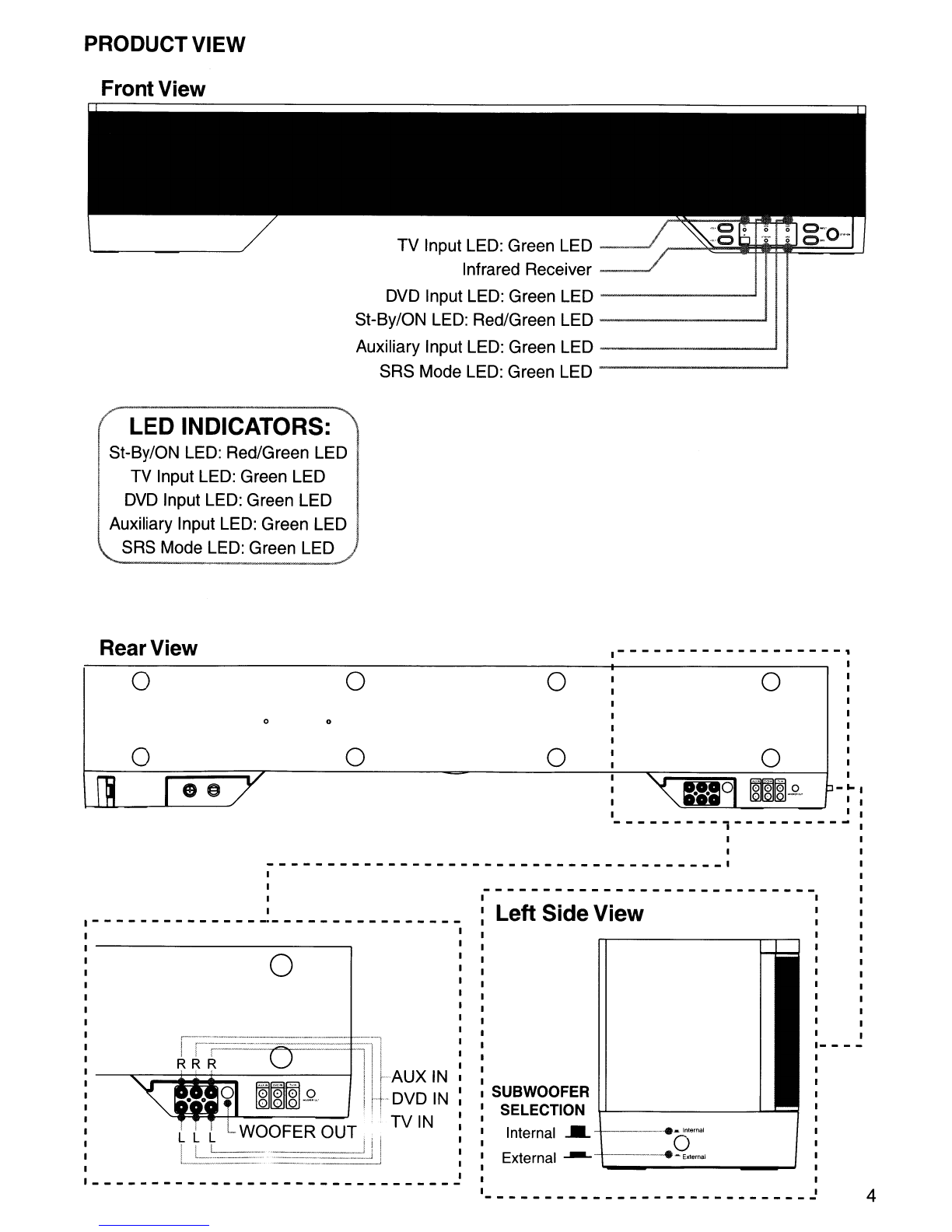
PRODUCTVIEW
FrontView
TV Input LED: Green LED
_---F
".-~~*:t*F~==~.J
Infrared Receiver
_---F
DVD Input LED: Green LED
------~
St-By/ON LED: Red/Green LED
---------1
Auxiliary Input LED: Green LED .....1
SRS Mode LED: Green LED
----------'
LED INDICATORS:
St-By/ON LED: Red/Green LED
TV Input LED: Green LED
DVD Input LED: Green LED
Auxiliary Input LED: Green LED
SRS Mode LED: Green LED
o
o
"'r
_01
~Fol
a
~
-w. I
lWJlQJ-'·-
.-------------------,
1
1
1
1
1
1
1
1
1
1
3-
~
1
1
o
o
o
o
oo
o
o"
Rear View
Left Side View
---------j----------
I
I
--------------------------------_---
__
1
1
1
1
1
4
___
._Inlernal
o
------e
-External
External
---
"-_----
__
....J
SUBWOOFER
SELECTION
Internal
....
1-
--
1
1
I
I
I
I
1
1
1
1
1
___________________________
2
o
rtr=--===---
-IJAUX
IN
I
H-DVD
IN
WOOFER
OUT.
!ITV
IN
L~=::.:
__
-____
_U

REMOTE
CONTROL
REMOTE
CONTROL
BUTTON
CONFIGURATION
STANDBY/ON
MUTE
•
---++-----l
..
e+--H--8
e
prl?vCldO
BUTTON FUNCTIONS
..
Stand By/ON: Stand By/ON
..
Mute: No Sound
•TV: Select
TV
Input
•
DVD:
Select DVD Input
•AUX: Select Auxiliary Input
•SRS: SRS ON/SRS OFF
•Woofer
-:
Decrease Woofer Level
eWoofer
+:
Increase Woofer Level
eCrossover
-:
Decrease Woofer Frequency Response
G!)
Crossover
+:
Increase Woofer Frequency Response
•Volume
+:
Increase MasterVolume
48
Volume
-:
Decrease MasterVolume
SRS
•
---+~:-e
~H-++---.
'------+--~
0---++-------'
.-----+~~
•
r-----~+_++_-e
•
(0
.----++-----I~+
Requires (2) AAA Batteries
srs@
TruSurround
XT
SOUND
RETRIEVAL
SYSTEM
(SRS)
SRS
TruSurround
XT<'D
Sound Retrieval System (SRS) Labs understands how sound travels and how it
is
perceived
by the ears, this is called psycho acoustics. With this understanding, SRS Labs was able to
create asurround sound effect from only 2channels, thus eliminating the need for surround
sound speakers and additional wiring. This technology lead to the creation of SRS
TruSurround
XT,
which goes much further than the name states. It also increases the clarity
of the dialog and bass response while enjoying movies,
TV,
music, or video games.
In
some
instances the dialog
in
amovie can be lost or buried within the audio special effects, but
with SRS TruSurround XT the dialog will boost with clarity and the frequency range of the
human voice.
The SRS TruSurround XT is able to reproduce the sensation of deep bass from small
drivers by identifying the audio signals that can't be reproduced
without distortion and restoring and boosting those that can.
Providing abass response typically associated with amuch
larger driver.
5

OPERATION
Turning
ON
and
OFF
the
HS21
Turning
ON
the
HS21
After completing the connections between the
HS21
and the audio devices, turn the
HS21
ON by switching the toogle switch to the
ON
position.
The ST-BY/ON LED will illuminate Red indicating the
HS21
is
in
Stand By mode.
Press the ST-BY/ON button on the
HS21
or the STANDBY/ON button
on
the remote
control, the LED will illuminate Green indicating the
HS21
is
ON.
Turning OFF
the
HS21
Press the ST-BY/ON button on the
HS21
or the STANDBY/ON button
on
the remote
control, the LED will illuminate Red indicating the
HS21
is
in
Stand
By
mode.
While
in
Stand
By
mode, the
HS21
will retain the memory last source selected, volume,
woofer volume and frequency setting.
Selecting Audio Sources
Selecting
Audio
Sources
from
the
HS21
Control
Panel
Press the INPUT button on the
HS21
to cycle through the various audio sources.
(TV -->
DVD
--> AUX --> TV) AGreen LED will indicate the selected audio source.
Selecting
Audio
Sources
from
the
Remote
Control
Press the desired audio source button on the remote control.
(TV,
DVD,
AUX)
AGreen LED will indicate the selected audio source.
Adjusting theVolume
Increasing
the
Volume Level
Press the VOL+ button
on
the
HS21
or Volume +button
on
the remote control.
The Green ST-BY/ON LED will flicker indicating the increase
in
volume. The LED will
emit solid
if
the maximum volume level has been reached.
Decreasing
the
Volume Level
Press the VOL- button on the
HS21
or Volume -button on the remote control.
The Green ST-BY/ON LED will flicker indicating the decrease
in
volume. The LED will
emit solid if the minimum volume level has been reached.
Muting
the
Audio
Press the MUTE button
on
the remote control to mute the audio.
The Green ST-BY/ON LED will blink while
in
the mute mode.
Press the MUTE button on the remote control to unmute the audio.
Pressing the Volume +/- or Woofer +/- will also unmute the audio.
6
OPERATING
THE
HS21
(continued)
Sound Retrieval System (SRS) Function
Turning ON the SRS Function
Press the SRS button on the HS21 or SRS button on the remote control.
The Green SRS LED will illuminate while SRS mode is ON.
Turning OFF the SRS Function
Press the SRS button on the HS21 or SRS button
on
the remote control.
The Green SRS LED will turn off indicating SRS mode is
OFF.
Adjusting the Subwoofer Level
Increasing the Subwoofer Level
Press the Woofer +button on the remote control.
The Green ST-BY/ON LED will flicker indicating the increase
in
the subwoofer level.
The LED will emit solid if the maximum woofer level has been reached.
Decreasing the Subwoofer Level
Press the Woofer -button on the remote control.
The Green ST-BY/ON LED will flicker indicating the decrease
in
the woofer level.
The LED will emit solid if the minimum woofer level has been reached.
Adjusting the Crossover Frequency Level
The
HS21
has avariable crossover frequency from 30-180Hz.
Increasing the Crossover Frequency Level
Press the Crossover +button on the remote control.
The Green ST-BY/ON LED will flicker indicating the increase in the crossover frequency.
The LED will emit solid if the maximum frequency level has been reached.
Decreasing the Crossover Frequency Level
Press the Crossover -button on the remote control.
The Green ST-BY/ON LED will flicker indicating the decrease
in
the crossover frequency.
The LED will emit solid if the minimum frequency level has been reached.
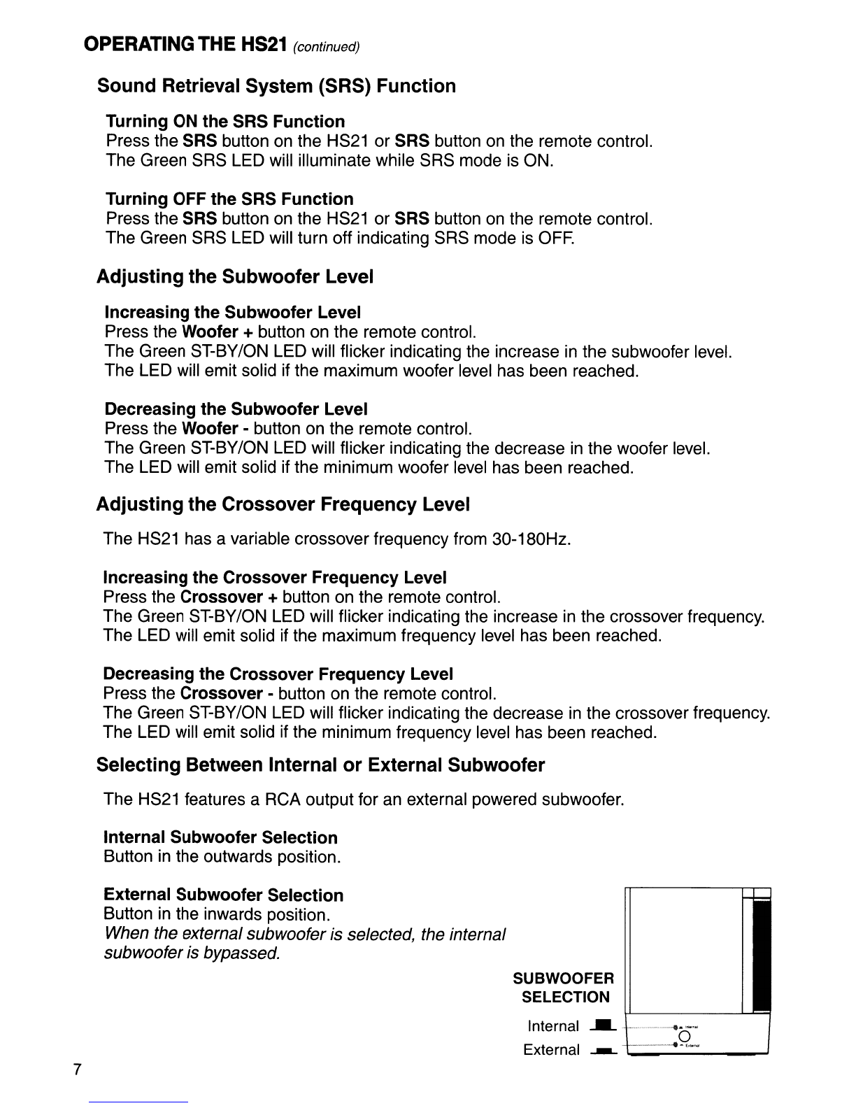
Selecting Between Internal or External Subwoofer
The HS21 features aRCA output for an external powered subwoofer.
Internal Subwoofer Selection
Button
in
the outwards position.
7
External Subwoofer Selection
Button
in
the inwards position.
When the external subwoofer is selected, the internal
subwooferis bypassed.
SUBWOOFER
SELECTION
Internal
___-
..
.... -
...
o
External ----------e-,,,.-

CONNECTIONS
Connecting Audio Sources
How to Connect aTV to the HS21
1.
Locate the audio output from the
TV.
2. Connect aRCA cord from the TV audio output to the TV input located on the back of
the HS21.
If
the audio output from the
TV
utilizes a3.5mm stereo minijack, it will require an optional3.5mm
stereo minijack to RCA adapter.
If
the audio output from the
TV
is amono signal, it will require
an
optional3.5mm
mono
jack
to 2
RCA adapter.
How to Connect aDVD Player to the
HS21
1.
Locate the audio output from the
DVD
player.
2.
Connect aRCA cord from the
DVD
player audio output to the
DVD
input located on
the back of the HS21.
How to Connect Any Audio Source to the HS21
1.
Locate the audio output from the audio source.
2.
Connect aRCA cord from the audio source to the AUX input located on the back of
the HS21.
If
the audio output from the audio source utilizes a3.5mm stereo
mini
jack, it will require an optional
3.5mm stereo mini
jack
to RCA adapter.
If
the audio output from the audio source is amono signal, it will require
an
optional3.5mm mono
jack
to 2RCA adapter.
o
o0
o o o
o
R(RED)
o
L(WHITE)
o
~
~
120V
rL
~~
g
~~
(TV,
DVD player, Game Station, Computer, Portable Music Player, etc.)
8

CONNECTING AN OPTIONAL POWERED SUBWOOFER
Connection
WOOFER
SELECTION
;--j
~~
e
(C'
i:~
j
~iBiL.
------~--
... Inlernal
o
External
----E""""
NOTE:
The
Woofer Selection button
must be
in
the inward position for the
external subwoofer output to be active.
How
to
Connect
an
Optional
Powered
Subwoofer
to
the
HS21
1.
Turn OFF the power switch
on
the HS21.
2.
Place the optional powered subwoofer according
the manufacture's recommendation.
3.
Plug aRCA cord into the WOOFER OUT located
on the back of the H
S21
.
4.
Connect the other end of the RCA cord into the
audio input
on
subwoofer.
5.
Press the WOOFER SELECTION button
on
the
HS21
to
the inward position.
6.
Consult the owner's manual for the optional
powered subwoofer for recommended set
up
and
setting before turning on the HS21.
7.
Turn
ON
the power switch
on
the
HS21
.
Optional Powered Subwoofer
(Sold Separately)
RCA Cord
.----------.--.-.
o :
I
I
I
o :
I
"<::
1119
~.g.
~:
1 - ...
Adjusting the Level Woofer
Increasing
the
Woofer Level
Press the Woofer +button on the remote control.
The Green ST-BY/ON LED will flicker indicating the increase
in
the woofer level.
The LED will emit solid if the maximum woofer level has been reached.
Decreasing
the
Woofer Level
Press the Woofer -button on the remote control.
The Green ST-BY/ON LED will flicker indicating the decrease
in
the woofer level.
The LED will emit solid if the minimum woofer level has been reached.
Adjusting the Crossover Frequency Level Woofer
The
HS21
has avariable crossover frequency from 30-180Hz.
Increasing
the
Crossover
Frequency
Level
Press the
Crossover
+button on the remote control
The Green ST-BY/ON LED will flicker indicating the increase
in
the crossover frequency.
The LED will emit solid if the maximum frequency level has been reached.
Decreasing
the
Crossover
Frequency
Level
Press the
Crossover
-button on the remote control.
The Green ST-BY
ION
LED will flicker indicating the decrease
in
the crossover frequency.
The LED will emit solid if the minimum frequency level has been reached.
9

HS21 LOCATION OPTIONS
Below
TV
on
TV Stand or Table BelowTV Wall Mounted
Above
TV
on
TV
Stand orTable Above TV Wall Mounted
II
NOTE:
It
is
highly recommended aqualified technician perform the installation of wall mounting
the Prevado HS21. The HS21 wall mounting brackets provide enough adjustment so the
mounting brackets can be mounted to the wall studs.
Do not hang and/or place objects
on
to the HS21. Doing so can result
in
damage to the
HS21,
TV,
wall, etc. and possibly injury or death.
INCLUDED ACCESSORIES
Remote Control
Requires (2) AAA Batteries User's Guide 5' Stereo RCA Cable Wall Mounting Hardware 10

prE?
0,
Distributed by:
Clarion Corporation of America
6200 Gateway Drive
Cypress,
CA
90630
TruSurround
XT,
SRS, and the @symbol are trademarks of SRS Labs, Inc.
TruSurround XTtechnology is incorporated under license from SRS Labs, Inc.
2009/05 All Rights Reserved. Copyright©2009: Clarion Corporation of America
Printed
in
China
12578400
HS21
Table of contents


