PREVOST GKN AXLES LIMITED KIRKSTALL DIVISION User manual

16-1
SECTION 16: SUSPENSION
CONTENTS
1. DESCRIPTION......................................................................................................................................... 16-3
2. AIR SPRING ............................................................................................................................................ 16-4
2.1 Inspection........................................................................................................................................ 16-4
2.2 Removal.......................................................................................................................................... 16-4
2.3 Installation....................................................................................................................................... 16-4
3. SHOCK ABSORBER............................................................................................................................... 16-5
3.1 Inspection........................................................................................................................................ 16-5
3.2 Removal.......................................................................................................................................... 16-5
3.3 Installation....................................................................................................................................... 16-6
4. RADIUS ROD........................................................................................................................................... 16-6
4.1 Inspection........................................................................................................................................ 16-6
4.2 Removal.......................................................................................................................................... 16-7
4.3 Bushing Removal ........................................................................................................................... 16-7
4.4 Bushing Installation......................................................................................................................... 16-7
4.5 Installation....................................................................................................................................... 16-7
5. SWAY BAR 16-8
5.1 Removal.......................................................................................................................................... 16-8
5.2 Installation....................................................................................................................................... 16-8
6. SUSPENSION AIR SYSTEM.................................................................................................................. 16-9
6.1 Description...................................................................................................................................... 16-9
6.2 Inspection........................................................................................................................................ 16-9
6.3 Air Line Test.................................................................................................................................... 16-9
6.4 Air Tank Maintenance..................................................................................................................... 16-9
7. SUSPENSION HEIGHT ADJUSTMENT................................................................................................. 16-9
8. HEIGHT CONTROL VALVE.................................................................................................................. 16-10
8.1 Operation......................................................................................................................................16-10
8.1.1 Loading Position................................................................................................................16-10
8.1.2 Neutral Position.................................................................................................................. 16-10
8.1.3 Unloading Position.............................................................................................................16-10
8.2 Maintenance................................................................................................................................. 16-10
8.2.1 Removal and Installation...................................................................................................16-11
8.2.2 Air Leakage Test................................................................................................................16-11
9. FRONT KNEELING AND HI-BUOY SYSTEM (IF APPLICABLE)........................................................ 16-12
9.1 Principles of Operation.................................................................................................................16-12
9.2 Maintenance................................................................................................................................. 16-12
9.3 Keeling Sense Switch...................................................................................................................16-13
9.4 Bellows Control and Exhaust Solenoid Valves............................................................................16-13
9.4.1 Removal and Installation...................................................................................................16-13
10. HI-BUOY SYSTEM................................................................................................................................16-13
10.1 Principles of Operation.................................................................................................................16-13

Section 16: SUSPENSION
16-2
11. LOW-BUOY SYSTEM ...........................................................................................................................16-13
11.1 Principles of Operation................................................................................................................. 16-13
12. "LEVEL-LOW" LEVELING SYSTEM (IF APPLICABLE)....................................................................... 16-14
12.1 Principles of Operation.................................................................................................................16-14
13. DRIVE AXLE STABILIZER RESERVOIR (XL-45 CONVERTED VEHICLE).......................................16-15
13.1 Lubrication (Fig. 17).......................................................................................................................16-15
14. TROUBLESHOOTING .......................................................................................................................... 16-16
15. PARTS SPECIFICATIONS....................................................................................................................16-16
16. TORQUE SPECIFICATIONS................................................................................................................16-17
LIST OF ILLUSTRATIONS
FIG. 1: FRONT SUSPENSION COMPONENTS......................................................................................... 16-3
FIG. 2: REAR SUSPENSION COMPONENTS...........................................................................................16-3
FIG. 3: AIR SPRING.....................................................................................................................................16-4
FIG. 4: SHOCK ABSORBER........................................................................................................................ 16-6
FIG. 5: TYPICAL SHOCK ABSORBER SETUP.......................................................................................... 16-6
FIG. 6: TYPICAL RADIUS ROD SETUP ..................................................................................................... 16-6
FIG. 7: RADIUS ROD BUSHING REMOVAL.............................................................................................. 16-7
FIG. 8: RADIUS ROD BUSHING INSTALLATION......................................................................................16-7
FIG. 9: RADIUS ROD INSTALLATION........................................................................................................ 16-7
FIG. 10: SWAY BAR....................................................................................................................................... 16-8
FIG. 11: HEIGHT CONTROL VALVE ............................................................................................................ 16-9
FIG. 12: TYPICAL AIR SPRING CLEARANCE...........................................................................................16-10
FIG. 13: HEIGHT CONTROL VALVE .......................................................................................................... 16-11
FIG. 14: KNEELING/HI-BUOY PANEL (STEERING COMPARTMENT).................................................... 16-12
FIG. 15: KNEELING SENSE SWITCH.........................................................................................................16-13
FIG. 16: LEVEL-LOW PANEL (STEERING COMPARTMENT).................................................................. 16-14
FIG. 17: DRIVE AXLE STABILIZER RESERVOIR...................................................................................... 16-15

Section 16: SUSPENSION
16-3
1. DESCRIPTION
The vehicle is provided with an air suspension
system. The system consists of air springs, height
control valves, radius rods, sway bars and shock
absorbers (Fig. 1 and 2). The system operation is
fully automatic and maintains a constant vehicle
height regardless of load, or load distribution.
The vehicle can also be equipped with systems
such as Front kneeling & hi-buoy, Low-buoy, Hi-
buoy, and/or Level-low. For a description of all
these systems, refer to the appropriate heading in
this section.
FIGURE 1: FRONT SUSPENSION COMPONENTS 16026
FIGURE 2: REAR SUSPENSION COMPONENTS 16027

Section 16: SUSPENSION
16-4
2. AIR SPRING
The "rolling lobe" type air springs are made from a
special compound rubber molded to the proper
contour and dimensions. The entire vertical load
of the vehicle is supported by these springs. Each
of the three axles is provided with air springs that
are attached to the subframe and to the axles.
FIGURE 3: AIR SPRING 16007
2.1 Inspection
1. Check operation of bellows.
2. Visually inspect bellows for evidence of cracks,
punctures, deterioration, or chafing. Replace
the bellows if any damage is evident.
3. With the primary air system at normal operat-
ing pressure (95 - 125 psi (655 - 860 kPa)),
coat all suspension air line connections and
bellows mounting areas with a water and soap
solution. Bubbles will indicate an air leak, and
none is permissible. Repair or replace defec-
tive parts.
Note: If air spring is removed from vehicle,
bellows can be lightly inflated and submerged
in water to detect any leakage. If any leakage
is detected, replace bellows.
Warning: To prevent personal injury, do not
apply more than 10 psi (69 kPa) air pressure
with the air spring unmounted.
2.2 Removal
Note: Suspension air springs (front, drive,
and tag axles) can be removed without re-
moving the entire axle assembly.
1. Safely support vehicle at the recommended
body jacking points.
To gain access to a given air spring, the corre-
sponding wheel can be removed as follows:
a) Jack vehicle until the tire clears the ground,
and place safety supports underneath
body.
Caution: Only the recommended jacking
points must be used as outlined in Section 18,
"Body".
b) Support the axle with a suitable hydraulic
floor jack at the recommended jacking
point.
c) Remove wheel.
2. Exhaust compressed air from accessory air
tank by opening drain cock under reservoir.
3. Disconnect the height control valve link and
pull down the overtravel lever to ensure all air
is exhausted from air springs.
Note: While performing this step, do not
change the height control valve overtravel
lever adjustment.
4. Disconnect air line from air spring, remove
elbow (if applicable), and cover both the line
end and fitting to prevent the entry of foreign
matter (Fig. 3).
5. Remove the two air springs upper nuts, and
then the two lower nuts (Fig. 3). Remove air
spring.
2.3 Installation
1. Compress air spring as necessary, then align-
ing studs with their holes, position air spring
between both the lower and upper supports.
Thread the lower nuts and the small upper nut
a few turns.
2. Tighten and torque the lower stud nuts, and
then the upper one to 20 - 25 lbf·ft (27 -
34 N·m) (Fig. 3).
3. Thread the remaining upper nut (large nut) and
tighten to 20 - 25 lbf·ft (27 - 34 N·m) (Fig. 3).
4. Install elbow (if applicable), then connect air
line (Fig. 3).
5. Connect the height control valve link.

Section 16: SUSPENSION
16-5
6. Build up air pressure in system.
Note: To accelerate this operation, air reser-
voirs can be filled from an exterior air supply
connected to the accessory tank fill valve or to
the emergency fill valve.
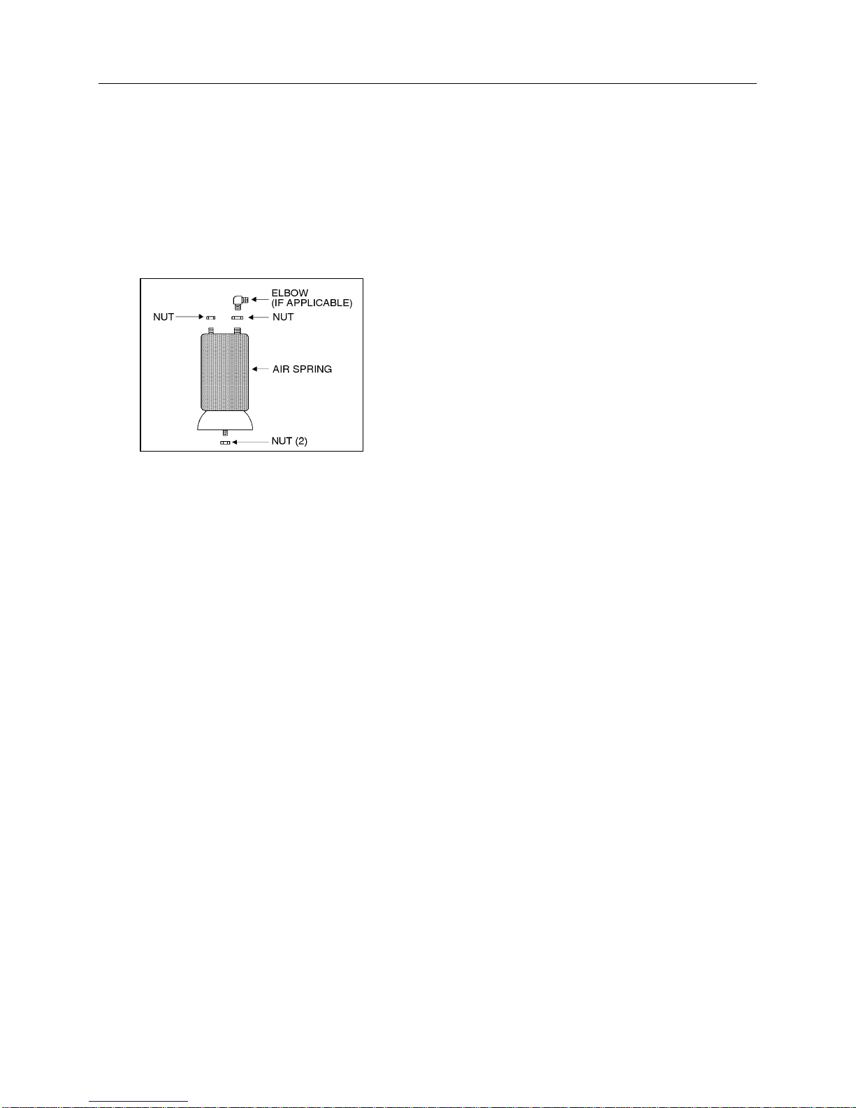
7. Check operation of bellows, and with the pri-
mary air system at normal operating pressure
(95 - 125 psi (655 - 860 kPa)), coat the air line
connections and air spring mounting areas
with a water and soap solution. Bubbles will in-
dicate an air leak, and none is permissible.
Repair or replace defective parts.
8. Remove the hydraulic floor jack from under the
axle, then lower vehicle to ground.
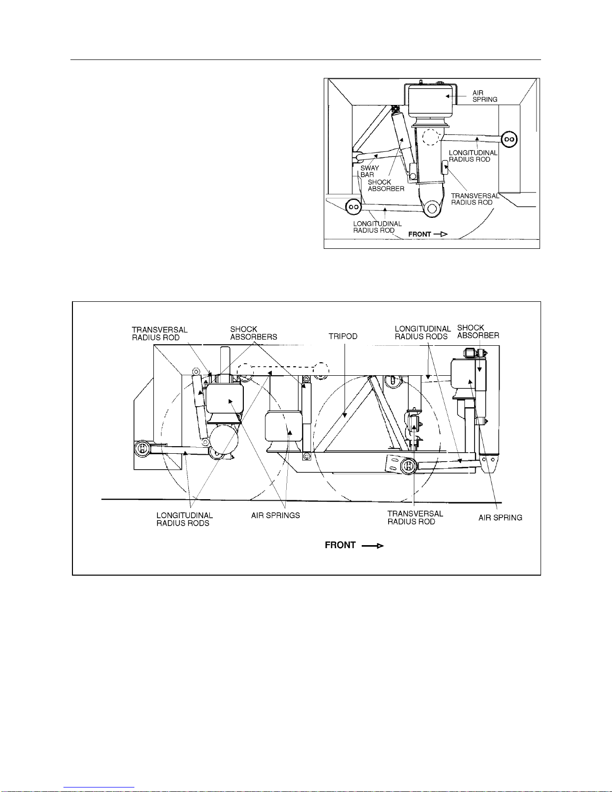
3. SHOCK ABSORBER
Double-action, telescoping-type shock absorbers
ensure a smooth ride and enhance vehicle stabil-
ity on the road. All shock absorbers are eye-type
mountings. The front and tag axles are each pro-
vided with two shock absorbers while the drive
axle is provided with four of them (Fig. 1 and 2).
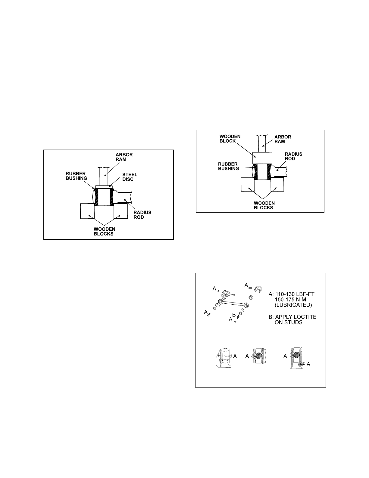
Shock absorbers are non-adjustable and non-
repairable. Maintenance requirements involve
replacement of the rubber mounting bushings,
and tightening of all shock absorber pins at the
proper torque (350 - 400 lbf·ft (475 - 545 N·m))
when shock absorber replacement occurs. If a
shock absorber becomes inoperative, complete
unit must be replaced.
Caution: When a shock absorber is found
defective, always replace with a new set on
affected axle, except if there has been a recent
replacement of one unit. The following method
will help in determining if both shock absorb-
ers on the same axle have to be replaced.
3.1 Inspection
Loosen lower mounting of both shocks, then
carefully attempt to raise and lower the bottom
portion of each shock. Note the rate of effort for
distance of travel. Replace both shocks if a defi-
nite differential rate is found.
The shock must be bench checked in an upright,
vertical position. If checked in any other position,
air will enter the cylinder tube and make the shock
absorber appear defective.
Proceed as follows to check shock absorbers:
1. With the shock absorber in a vertical position
(top end up), clamp the bottom mount in a
vise.
Caution: Do not clamp the reservoir tube or
the dust tube.
2. Rotate the dust tube. Notice any binding con-
dition (may be compared with new unit). Bind-
ing condition indicates a scored rod. Units with
scored rods should be replaced.
3. Fully extend shocks and check for leaks in the
seal cover area. Shock fluid is a very thin hy-
draulic fluid that has a characteristic odor and
dark brown tint. A slight trace of shock fluid
around the seal cover area is not a cause for
replacement. The shock seal is designed to
permit a very slight seepage to lubricate the
rod. Units which leak should be replaced.
4. Visually check shock for dents that could
cause the shock to bind. Also, check for a bent
rod.
5. Extend and collapse shock to determine that it
has control (resistance) in both rebound and
compression.
6. Visually inspect the shock mountings and ve-
hicle mountings for:
a) Broken mounts;
b) Extreme bushing wear;
c) Shifted bushing or sleeve;
d) Deep cracks in bushing material (shallow
surface cracks are normal);
e) Loose shock absorber pins;
f) Presence of convex washers, and their po-
sition according to the rubber bushing.
3.2 Removal
1. Remove nuts and washers from shock ab-
sorbers on upper and lower mounting pins,
taking care to identify the inner and outer
washers to ease reinstallation. Refer to fig-
ure 4 for details.

Section 16: SUSPENSION
16-6
FIGURE 4: SHOCK ABSORBER 16008
2. Remove the shock absorber assembly from
pins.
3. Remove the two inner bushings from the
shock absorber, and discard them.
3.3 Installation
1. Ensure that the shock absorber mounting pins
are tight and that the threads are not stripped.
2. Install new rubber mounting bushings on
shock absorbers (upper and lower).
3. Place the inner washers (with washer convex
side facing the shock absorber rubber bush-
ing) on each shock absorber pin (Fig. 5).
FIGURE 5: TYPICAL SHOCK ABSORBER SETUP 16009
4. Install the shock absorber eyes over the
mounting pins, then the outer washers (with
washer convex side facing the shock absorber
rubber bushing) on each shock extremity.
5. Place the lower and upper mounting pin stud
nuts and torque them to 70 - 80 lbf·ft (95 -
110 N·m).
4. RADIUS ROD
Radius rods are used to secure the axles in the
proper transversal and longitudinal positions. Four
radius rods are provided on the front axle suspen-
sion (three longitudinal and one transversal), four
on the drive axle suspension (three longitudinal
and one transversal) and also four on the tag axle
with a layout similar to the drive axle. Refer to
figures 1 and 2 for details. These rods transmit
both braking and driving forces from the axles to
the vehicle body.
FIGURE 6: TYPICAL RADIUS ROD SETUP 16010
4.1 Inspection
The following instructions apply to all radius rods
used on this vehicle:
1. Clean all parts thoroughly.
2. Inspect radius rods for distortion and cracks.
We recommend the "Magnaflux" process to
detect cracks in the radius rod. Any damaged
part should be replaced with a new one.
Note: New bushings should be used when
rods are replaced.
3. The radius rod bushings should be checked
periodically for signs of shearing, deterioration,
or damage. Any defective part should be re-
placed with a new one.

Section 16: SUSPENSION
16-7
4.2 Removal
1. Flatten the tab washer which secures the two
retaining nuts (or bolts), then unscrew the nuts
(or bolts) at each extremity of the radius rod
(Fig. 6).
2. Remove the tab washer and the retaining
plates and radius rod ends from anchor pins,
then remove the radius rod.
4.3 Bushing Removal
1. Safely support the radius rod as shown in fig-
ure 7.
FIGURE 7: RADIUS ROD BUSHING REMOVAL 16011
2. Place a flat steel disc, slightly smaller than the
outside diameter of the bushing (Fig. 7).
3. Using an arbor press or a suitable driving tool,
press or drive the old bushing out of the rod
and discard the bushing.
Caution: Make sure to prevent the steel disc
from contacting radius rod end.
4.4 Bushing Installation
1. Lightly Spray the inner and outer surfaces of
radius rod bushing with water.
Caution: No lubricant whatsoever is to be
used on the rubber bushing.
2. Safely support the radius rod, and place new
bushing on top of the radius rod end (Fig. 8).
3. Place a block of wood on top of bushing and
press on it manually.
4. If necessary, use an arbor press or a suitable
driving tool. Press or drive the bushing into the
radius rod end until it extends equally on both
sides of the rod.
5. It is also possible to proceed differently. Place
radius rod bushing on a plane surface. Spray a
light coat of water on the inner and outer sur-
faces of radius rod bushing.
6. Take radius rod, align the bushing. Tap radius
rod on bushing until latter is positioned cor-
rectly.
FIGURE 8: RADIUS ROD BUSHING INSTALLATION 16012
4.5 Installation
1. Lightly Spray the anchor pin with water. Place
the radius rod end over the anchor pin.
FIGURE 9: RADIUS ROD INSTALLATION 16028

Section 16: SUSPENSION
16-8
2. Position the retaining plate. Install the tab
washer and nuts (or bolts).
Caution: Always use new tab washers at
installation.
3. Tighten the nuts (or bolts) lightly, and repeat at
the other end.
4. Refer to heading "Suspension height adjust-
ment" later in this section, and set the vehicle
to normal ride height.
5. With the vehicle at normal ride height, apply oil
on threads and tighten all radius rod anchor
pin nuts or bolts to 110 - 130 lbf·ft (150 -
175 N·m).
Caution: It is extremely important upon re-
connection of the rods that the proper clear-
ance height between the axle and body is
maintained. Otherwise, the rubber bushings in
radius rod ends will become preloaded, thus
reducing the life of these parts.
5. SWAY BAR
A sway bar is provided on the front axles to increase vehicle stability (Fig. 1). It controls lateral motion
(swaying movement) of vehicle.
FIGURE 10: SWAY BAR 16014
5.1 Removal
1. Disconnect the two links from sway bar.
2. Safely support the sway bar. Unbolt the four
bushing collars from subframe.
3. Remove sway bar.
Note: Sway bar bushings are slitted to ease
their removal.
5.2 Installation
1. Loosely install the sway bar.
2. Tighten the eight bushing collar nuts to 70 - 80
lbf•ft (95 - 110 N•m) (Fig. 10).
3. Tighten sway bar link upper nuts to 100 - 120
lbf•ft (136 - 163 N•m) and lower nuts to 70 - 80
lbf•ft (95 - 110 N•m) (Fig. 10).

Section 16: SUSPENSION
16-9
6. SUSPENSION AIR SYSTEM
6.1 Description
The suspension air system has its own air reser-
voir (accessory tank) which is located above the
front axle. Pressurized air from the main tank (wet
tank) flows through a pressure protection valve
(PR-2) installed on the accessory air tank, then
flows to the accessory air tank.
The pressure protection valve (PR-2) controls the
pressure at which compressed air would be deliv-
ered to the accessory air tank. The valve remains
closed until a preset pressure is reached (ap-
proximately 75 psi (517 kPa)). It then opens and
passes air out the delivery port.
The main use for this valve is to protect the main
air system by ensuring at all times a sufficient air
pressure in the main system (i.e. air delivered to
the accessories will be shut off in case of a de-
crease in pressure).
Another protection valve (PR-2) is installed on the
manifold block, and insures at all times a minimum
pressure of 75 psi (517 kPa) in suspension air
system in the event that a pressure drop occurs in
either the suspension air system or accessory air
system. This valve is located in the steering com-
partment
Maintenance and repair information on the pres-
sure protection valve is supplied in the applicable
booklet, annexed to Section 12, "Brakes and Air
System" under reference number SD-03-55.
6.2 Inspection
The following inspection should be performed at
established service inspection periods. Performing
these procedures will allow substandard perform-
ance to be discovered before the condition be-
comes bad enough to cause operator complaints
and failure on a run.
1. Visually inspect the suspension air lines for
evidence of chafing on metal parts or other
damage.
2. Visually inspect the air springs for cracks,
abrasion or other damage.
3. Replace any parts found to be damaged.
6.3 Air Line Test
With the main air system at normal operating
pressure (95 - 125 psi (655 - 860 kPa)), coat all
suspension air line connections and air spring
mountings with a solution of soap and water. Air
leakage will produce soap bubbles. Any leak
found must be corrected as no air leakage is per-
missible.
6.4 Air Tank Maintenance
Refer to Section 12, "Brakes and Air System"
under paragraph "2.2 Maintenance" for complete
instructions on air tank maintenance.
7. SUSPENSION HEIGHT
ADJUSTMENT
The flow of pressurized air from the accessory air
tank to the air springs is controlled by three height
control valves. These valves are mounted to the
subframe and connected to the axles through an
arm and link connection. This connection allows
the valves to apportion air pressure in the springs
to the vehicle load, maintaining normal ride height.
Immediate response height control valves in-
crease or decrease the air pressure in the sus-
pension system as required. One height control
valve is located at center of front axle, and regu-
lates air to front axle air springs in order to main-
tain the vehicle at the required height. Two are
located at the drive axle, one on each inner side of
rear wheelhouse. Refer to figure 11.
FIGURE 11: HEIGHT CONTROL VALVE 16029

Section 16: SUSPENSION
16-10
The appropriate vehicle body height is obtained by
measuring the clearance of all the air springs
installed on the vehicles. All air springs clearance
should be 11.5 ± 0.25" (292 ± 6 mm). Refer to
figure 12 to identify the correct location where the
measure has to be taken. At this point, it should
not be necessary to make an adjustment under
normal service conditions. However, if an adjust-
ment is required, change the position of the over-
travel lever in relation to the overtravel control
body. The lever should be moved up to raise the
height of vehicle, and down to lower it. Check that
main air pressure is at normal operating pressure
and raise the vehicle to the specified height.
Caution: Always adjust on "fill cycle". If it is
necessary to lower vehicle height, release
sufficient air to be well below height, and ad-
just to height or fill cycle.
The normal ride height is obtained by adjusting air
spring clearance of both front and rear
suspensions as follows:
1. With the vehicle at normal operating air pres-
sure (95 - 125 psi (655 - 860 kPa)), measure
air spring clearance as illustrated in figure 12.
This clearance should be 11.5 ± 0.25" (292 ± 6
mm) for all the air springs.
FIGURE 12: TYPICAL AIR SPRING CLEARANCE 16018
Note: The measure should be taken from
under the upper air spring support on sub-
frame to top of the lower air spring support on
axle (refer to fig. 12 for more details). If ad-
justment is required, begin with the drive axle.
2. Loosen the adjusting nuts on the connecting
rod of height control valve to raise or lower the
overtravel lever until the desired clearance is
reached (Fig. 13).
Note: Allow suspension to stabilize before
taking reading.
3. When the desired height is obtained, tighten
adjusting lock nuts to 2 - 4 lbf-ft (2,5 - 5 N-m)
(Fig. 13).
8. HEIGHT CONTROLVALVE
8.1 Operation
The height control valves automatically add air to,
or release air from air springs to maintain constant
suspension height regardless of load, or load
distribution. Each valve adjusts independently
according to the following conditions:
8.1.1 Loading Position
As the load increases and lowers the vehicle
body, the overtravel lever commands the height
control valve to add air to air springs.
8.1.2 Neutral Position
When vehicle body reaches the normal ride
height, the height control valve overtravel lever
reaches the "neutral" position and keeps both the
supply and exhaust ports closed to ensure normal
ride height is maintained. This condition remains
static until the vehicle load is altered.
8.1.3 Unloading Position
As the load decreases and raises the vehicle
body, the overtravel lever commands the height
control valve to release air from air springs.

Section 16: SUSPENSION
16-11
8.2 Maintenance
The height control valve requires no periodic
maintenance. Height control valve linkage oper-
ates on rubber bushings and no lubrication should
be attempted at this point.
8.2.1 Removal and Installation
Before disconnecting any height control valve air
lines, securely support the vehicle by its jacking
points on the body, and place safety support
underneath body. Refer to paragraph "16. Vehicle
Jacking Points" in Section 18, "Body".
Note: The XL-40 coach battery main
disconnect switch door gives access to the
rear right height control valve.
FIGURE 13: HEIGHT CONTROL VALVE 16030
1.To gain access to a rear height control valve,
the corresponding wheel and mudguard can
be removed.
2.Exhaust air from air system by opening the
drain cock of each air reservoir. Remove
height control valve.
3.Disconnect overtravel lever from link and pull
down lever to exhaust remaining air from air
springs.
4.Disconnect air supply and delivery lines from
the height control valve. Cover ends of the
lines with tape to prevent the entry of foreign
matter (Fig. 11).
5.Remove the two nuts retaining the height con-
trol valve to the mounting bracket, then re-
move valve assembly (Fig. 13).
Reverse removal procedure to replace height
control valve. After installation, check for leakage
using a soap and water solution.
8.2.2 Air Leakage Test
Note: The following procedure applies when
valve assembly has been removed from vehi-
cle.
1. Remove the height control valve from vehicle,
and clean thoroughly the exterior of valve as-
sembly.
2. Connect air pressure line to air inlet port, then
allow air pressure build-up (70- 100 psi (480 -
690 kPa)).
3. Dip the valve assembly in a container of water,
and watch for air bubbles when the overtravel
lever is in the center position. No air should
escape from any point of the valve assembly.
4. If bubbles appear from the air spring port, this
is an indication that the air inlet valve assembly
is defective and must be replaced.
5. Remove air pressure line from air inlet fitting
and connect it to the air spring port. If bubbles
appear at the air inlet check valve port, this is
an indication that check valve unit is defective
and must be replaced.
6. If bubbles appear at the exhaust port, this is an
indication that the exhaust valve assembly is
defective and must be replaced.
7. If bubbles appear around edge of valve cover
plate, the cover plate gasket must be replaced.
8. If no leaks are found, remove valve assembly
from water, then with air pressure still con-
nected to the air spring port, actuate overtravel
lever to remove any excess water which may
have entered exhaust valve chamber. Remove
air line, connect it to the air inlet port, and re-
peat operation to remove water from the air
inlet valve chamber.

Section 16: SUSPENSION
16-12
9. FRONT KNEELING AND HI-
BUOY SYSTEM (IF
APPLICABLE)
The kneeling system is used to lower front of ve-
hicle. This allows passengers to board the vehicle
with greater ease. The kneeling action is achieved
by exhausting air from the front air springs (bel-
lows). This system bypasses the height control
valve to provide a fast up and down movement of
the front suspension. Only five seconds are re-
quired to lower vehicle from normal level to the
lower position, and approximately nine seconds to
raise it. This quick response is achieved by the
kneeling air tank installed in front of steering (for
exact position, refer to Section 12, paragraph "2.1
Location and Function"). This tank provides suffi-
cient air supply to the kneeling system for some
successive operations.
FIGURE 14: KNEELING/HI-BUOY PANEL (STEERING
COMPARTMENT) 16031
The system is provided with two safety features;
first, a speed switch will enable the kneeling sys-
tem to work only under 5 mph (8 km/h). Secondly,
the parking brake is automatically applied, and a
limit switch will keep it applied as long as the vehi-
cle has not returned to a certain height where the
driver will be able to manually remove the parking
brake.
The purpose of the hi-buoy function in this system
is to raise the front end of the vehicle to allow
passengers to board the vehicle with greater
ease. It is also used to allow an extra ground
clearance for particular situations. In normal con-
ditions, the height control valve is in operation and
only the hi-buoy can be operated.
9.1 Principle of Operation
Refer to the system pneumatic diagram annexed
in the technical publication box provided with the
vehicle.
DOWN:
Both the bellows control and bellows exhaust
solenoid valves are energized, so the air control
valves release air from front air springs. The
height control valve is bypassed to ensure no air
is forwarded to air springs while lowering the front
suspension (Fig. 14).
UP:
Only the bellows control solenoid valve is ener-
gized, so the air coming from the kneeling air tank
is routed through air control valves, and up to front
air springs (Fig. 14). The height control valve is
bypassed until the kneeling proximity switch sig-
nals the kneeling module to cut off the bellows
control solenoid valve, about 1" (25 mm) below
normal ride height. The final height adjustment is
achieved by the height control valve.
HI-BUOY FUNCTION:
Only the bellows control solenoid valve is ener-
gized, so the air coming from the kneeling air tank
is routed through air control valves, and up to front
air springs (Fig. 14). The height control valve is
bypassed during the up motion. However, the
down motion is achieved through the height con-
trol valve.
9.2 Maintenance
Since the kneeling action is issued from both the
air system and electrical system, refer to Section
12, "Brake and Air System"and Section 06,
"Electrical System".
For diagnosis and understanding of the system,
refer to wiring diagrams along with the appropriate
system pneumatic diagram annexed in the
technical publication box provided with the
vehicle.

Section 16: SUSPENSION
16-13
9.3 Kneeling Sense Switch
The kneeling sense switch is bolted to the same
bracket as for the front height control valve, right
over the steering axle.
FIGURE 15: KNEELING SENSE SWITCH 16032
9.4 Bellows Control and
Bellows Exhaust Solenoid
Valves
9.4.1 Removal and Installation
1. On the right wall of steering compartment,
locate both the bellows control and bellows
exhaust solenoid valves (Fig. 14).
2. Identify hoses and wires to ease reinstallation.
Disconnect solenoid wires and the three flexi-
ble hoses from solenoid valves.
3. Unscrew and remove the control solenoid
valve and exhaust solenoid valve assembly.
Place on a clean working place.
Reverse removal procedure to reinstall.
Caution: Any cable tie that has been cut
during removal procedure should be replaced
with a new one.
10. HI-BUOY SYSTEM
The purpose of the hi-buoy system is the raise
vehicle body about 4" (100 mm) in order to in-
crease ground clearance to board a ferryboat, to
avoid a curb, etc.. This system can be put into
service during normal vehicle operation.
10.1 Principles of Operation
Refer to the system pneumatic diagram annexed
in the technical publication box provided with the
vehicle.
UP:
The air coming from the control valve on R.H.
lateral console, flows through a quick release
valve, then through double shuttle valves, to finally
supply air springs. The double shuttle valves pre-
vent height control valves from releasing air from
air springs.
DOWN:
The control valve, on the dashboard, cuts off air
supply, so the double shuttle valves allow height
control valves to accomplish their function. Height
control valves release air from air springs until
suspension reaches the normal ride height.
11. LOW-BUOY SYSTEM
The purpose of the low-buoy system is to lower
the whole suspension about 4" (100 mm) in order
to reduce the overall height for low clearances.
This system can be put into service during normal
vehicle operation.
11.1 Principles of Operation
Refer to the system pneumatic diagram annexed
in the technical publication box provided with the
vehicle.
DOWN:
The control valve, on the R.H. lateral console
dashboard, cuts off air supply, so air is released
from air springs. A relay valve prevents height
control valves from supplying air springs.
UP:
The control valve, on the dashboard, supplies air
to close the passage between both the delivery
and supply ports. A relay valve opens and pro-
vides air springs until the suspension reaches the
normal ride height.

Section 16: SUSPENSION
16-14
12. "LEVEL-LOW" LEVELING
SYSTEM (IF APPLICABLE)
The purpose of the "level-low" leveling system is
to adjust suspension in three separate points
(front, rear right and rear left) in order to level
vehicle body. This system can be put into service
when the ignition key is turned to the "ON" posi-
tion, and must be used only when the parking
brake is applied. The "level-low" warning light on
the dashboard indicates that the selector knob is
not in the "DRIVE" position. Level low system
controls are located on L.H. side control panel.
12.1 Principles of Operation
Refer to the system pneumatic diagram annexed
in the technical publication box provided with the
vehicle.
DOWN:
The (front/rear right/rear left) control solenoid
valve supplies air to the (front/rear right/rear left)
five-way three-position air control valve, which
bypasses the (front/rear right/rear left) height con-
trol valve, and opens a passage to allow the air
control and exhaust valve to release air from
(front/rear right/rear left) air springs.
UP:
The (front/rear right/rear left) control solenoid
valve supplies air to the (front/rear right/rear left)
five-way three-position air control valve, which
bypasses the (front/rear right/rear left) height con-
trol valve, and opens a passage to allow the air
control and exhaust valve to supply air to
(front/rear right/rear left) air springs.
DRIVE:
When the ignition key is turned to the "ON" posi-
tion with selector knob in the "DRIVE" position, the
drive control solenoid valve supplies air to all five-
way three-position air control valves, each one
opening a passage to allow height control valves
to accomplish their function.
When the ignition key is turned to the "OFF" posi-
tion and selector knob to the "DRIVE" position, the
air is entrapped between air springs and five-way
three-position air control valves to ensure the
adjusted level will be kept.
Warning: Never move vehicle with selector
knob in any other position than the "DRIVE"
position.
FIGURE 16: LEVEL-LOW PANEL (STEERING
COMPARTMENT) 16033
13. DRIVE AXLE STABILIZER
RESERVOIR (XL-45
CONVERTED VEHICLE)
The rear stabilizer system makes turning the vehi-
cle easier. The only maintenance is to check oil
level in a reservoir. This reservoir is located in the
rear wheelhouse, before the drive axle (see under
the vehicle). Check oil level every 50,000 miles
(80 000 km) or once a year, whichever comes
first.

Section 16: SUSPENSION
16-15
FIGURE 17: DRIVE AXLE STABILIZER RESERVOIR 16034
13.1 Lubrication (Fig. 17)
The sight glass indicates if oil must be added to
the reservoir. If the small ball in the sight glass is
at the bottom of the sight glass then add oil to the
reservoir as per the following procedure:
1.Remove connector tube at the top of the res-
ervoir to permit air to enter.
2.Remove the fill plug.
3.Fill the reservoir with Dexron oil until oil reach
the bottom of filling plug.
4.Screw the fill plug and the connector tube on
the reservoir.

Section 16: SUSPENSION
16-16
14.TROUBLESHOOTING
MALFUNCTION POSSIBLE CAUSE CORRECTION
Bellows deflate over time Defective check valve assembly
Defective exhaust valve assembly
Leak in air line and/or bellows
Defective valve cover, rubber O-rings
or gasket
Replace check valve assembly
Replace exhaust valve assembly
Replace air line or bellows
Replace valve cover, O-rings or gas-
ket
Bellows raise to full height
and fail to exhaust air
pressure
A clogged exhaust screen in height
control valve assembly
A combination clogged exhaust screen
and defective air inlet valve assembly
Remove and clean screen
Clean exhaust screen and replace air
inlet valve assembly
Erratic valve action Dirt or foreign matter in the air valve
lever chamber
Defectives valves
Remove valve cover and blow out
dirt
Install cover using new gasket
Overhaul height control valve as-
sembly
Vehicle body fails to level
to satisfactory ride height Improper height control valve over-
travel lever adjustment Adjust lever as directed
15. PARTS SPECIFICATIONS
AIR SPRINGS
Front
XL-40 & XL-45E CONVERTED VEHICLES
Make............................ Goodyear Tire and Rubber
Model.....................................Roll-over volume can
Type ................................................................1100
Diameter............................................11" (279 mm)
Supplier number......................................1R11-089
Prévost number...........................................630105
ELSE
Make............................ Goodyear Tire and Rubber
Model................................................. M-West Long
Supplier number......................................1R11-096
Prévost number...........................................630126
Drive
Make............................ Goodyear Tire and Rubber
Model.....................................Roll-over volume can
Type ................................................................1100
Working diameter...........................11.5" (292 mm)
Supplier number......................................1R11-088
Prévost number...........................................630104
Tag
Make............................Goodyear Tire and Rubber
Model.................................................M-West Long
Supplier number ..................................... 1R11-096
Prévost number .......................................... 630126
SHOCK ABSORBERS
Front
FRONT ABSORBER - XL-45 COACH AND
CONVERTED VEHICLE (ONLY)
Make............................................................Gabriel
Collapsed length.......................... 15.47" (393 mm)
Extended length............................. 24.5" (622 mm)
Prévost number .......................................... 630134
ELSE
Make...........................................................Monroe
Type.................................................. Gas Magnum
Collapsed length....................... 15.38" (390,5 mm)
Extended length........................ 23.63" (600,1 mm)
Supplier number ......................................... 650407
Prévost number .......................................... 630127

Section 16: SUSPENSION
16-17
HEIGHT CONTROL VALVE
Make.............................................................Neway
Quantity used........................................................3
Supplier number....................................905 54 234
Prévost number...........................................630095
BELLOWS CONTROL AND EXHAUST
SOLENOID VALVE ASSEMBLY
Make...........................................................Norgren
Solenoid valve manifold
Supplier number.........................................D0043B
Prévost number...........................................641130
Coil
Voltage...................................................... 24 V DC
Current draw ...................................... 0.29 ampere
Supplier number.......................................54932-27
Prévost number...........................................641144
VALVE (3 WAYS, 2 POSITIONS)
Supplier number.................... K41EAOO-KH1-KS6
Prévost number..........................................63-0081
Repair kit (spool) Supplier number..........54237-65
Repair kit (spool) Prévost number..............641169
RADIUS ROD BUSHING
Make...........................................................Prévost
Prévost number .......................................... 630021
SWAY BAR BUSHING
Make...........................................................Prévost
Prévost number .......................................... 130953
SHOCK ABSORBER AND SWAY BAR LINK
BUSHINGS
Make...........................................................Monroe
Supplier number ........................................... 45380
Prévost number .......................................... 630062
16.TORQUE SPECIFICATIONS
1- Shock absorber pin...............................................................................................350-400 lbf·ft (475-545 N·m)
2- Shock absorber pin nut...............................................................................................70-80 lbf·ft (95-110 N·m)
3- Radius rod stud...................................................................................................................................LOCTITE
4- Radius rod retaining nut or bolt ..........................................110-130 lbf·ft lubricated (150-175 N·m lubricated)
5- Radius rod support nut.......................................................110-130 lbf·ft lubricated (150-175 N·m lubricated)
6- Axle attachment nut..............................................................................................425-475 lbf·ft (580-645 N·m)
7- Air spring stud nut.........................................................................................................20-25 lbf·ft (27-34 N·m)
8- Sway bar link pin stud...........................................................................................350-400 lbf·ft (475-545 N·m)
9- Sway bar link lower nut...............................................................................................70-80 lbf·ft (95-110 N·m)
10- Sway bar link upper nut......................................................................................100-120 lbf·ft (136-163 N·m)
Note:
During assembly, use "Loctite 242" (Prévost number 680038) with item 1, 3 and 8.
After assembly, apply "anti-seize compound" (Prévost number 680064) on all nuts.

16-1
SECTION 16:
SUPPLEMENT INFORMATION ON
INDEPENDENT FRONT SUSPENSION (IFS)
CONTENTS
1. INTRODUCTION.........................................................................................................................................16-4
2. STEERING LINKAGE.................................................................................................................................16-4
2.1 General Description.....................................................................................................................16-4
2.2 Turning Angle...............................................................................................................................16-5
2.3 Steering Linkage Adjustment.......................................................................................................16-8
2.4 Pitman Arm..................................................................................................................................16-8
2.4.1 Removal...........................................................................................................................16-8
2.4.2 Installation ........................................................................................................................16-8
2.5 Drag Link......................................................................................................................................16-8
2.5.1 Adjustment .......................................................................................................................16-9
2.6 Bell Crank and Idler Arm..............................................................................................................16-9
2.6.1 Bell Crank and Idler Arm Removal ..................................................................................16-9
2.6.2 Bell Crank and Idler Arm Ball joint Disassembly .............................................................16-9
2.6.3 Bell Crank and Idler Arm Ball joint Reassembly............................................................16-10
2.7 Relay Rod..................................................................................................................................16-11
2.7.1 Replacement..................................................................................................................16-11
2.8 Tie Rods.....................................................................................................................................16-11
2.8.1 Description and Maintenance........................................................................................16-11
2.8.2 Removal.........................................................................................................................16-11
2.8.3 Installation ......................................................................................................................16-12
2.9 Steering Arms............................................................................................................................16-12
2.9.1 Removal.........................................................................................................................16-12
2.9.2 Installation ......................................................................................................................16-12
2.10 Lubrication Fittings...................................................................................................................16-12
2.11 Power Steering Hydraulic Pump .............................................................................................16-14
3. INDEPENDENT FRONT SUSPENSION JOINTS ...................................................................................16-14
3.1 Lower and Upper A-arm Ball Joint (Bonded Rubber Bush)......................................................16-14
3.1.1 Instructions.....................................................................................................................16-14
3.1.2 Stripping Down...............................................................................................................16-14
3.1.3 Assembly........................................................................................................................16-14
3.2 Lower A-arm Central Joints (BT-Sectional Bearing System)....................................................16-16
3.2.1 Instructions.....................................................................................................................16-16
3.2.2 Stripping Down...............................................................................................................16-16
3.2.3 Assembly........................................................................................................................16-16
3.3 Upper A-arm Ball Joints (one-part Bearing System).................................................................16-18
3.3.1 Instructions.....................................................................................................................16-18
3.3.2 Stripping Down...............................................................................................................16-18
3.3.3 Assembly........................................................................................................................16-18
4. FRONT END ALIGNMENT.......................................................................................................................16-21
4.1 Definition of Terms.....................................................................................................................16-21
4.1.1 Wheel Camber...............................................................................................................16-21
4.1.2 Wheel Toe-In..................................................................................................................16-21
4.1.3 Front Axle Caster ...........................................................................................................16-21
4.1.4 King Pin Inclination.........................................................................................................16-21

Section 16: SUPPLEMENT INFORMATION ON INDEPENDENT FRONT SUSPENSION (IFS)
16-2
4.2 Front End Inspection..................................................................................................................16-21
4.3 Front Wheel Camber .................................................................................................................16-21
4.4 Front Wheel Toe-In....................................................................................................................16-21
4.5 Toe-In Check .............................................................................................................................16-21
4.6 Toe-In Adjustment .....................................................................................................................16-22
4.7 Front-Axle Caster.......................................................................................................................16-22
4.8 Major Damage...........................................................................................................................16-22
5. AIR SPRING MAINTENANCE (FRONT AIR SPRINGS).........................................................................16-24
5.1 Inspection...................................................................................................................................16-24
5.2 Removal.....................................................................................................................................16-24
5.3 Installation..................................................................................................................................16-25
6. SHOCK ABSORBER ................................................................................................................................16-26
6.1 Shock Absorber Removal..........................................................................................................16-26
6.2 Shock Absorber Installation.......................................................................................................16-26
7. SWAY BAR................................................................................................................................................16-26
7.1 Sway Bar (Front Suspension) ...................................................................................................16-28
7.1.1 Removal.........................................................................................................................16-28
7.1.2 Installation ......................................................................................................................16-28
7.2 Sway Bar (Drive Axle)..............................................................................................................16-28
7.2.1 Removal.........................................................................................................................16-28
7.2.2 Installation ......................................................................................................................16-28
8. INDEPENDENT FRONT SUSPENSION ADJUSTMENT........................................................................16-28
8.1 Suspension Height Adjustment..................................................................................................16-28
9. HEIGHT CONTROL VALVE.....................................................................................................................16-30
9.1 Operation ...................................................................................................................................16-30
9.1.1 Loading Position.............................................................................................................16-30
9.1.2 Neutral Position..............................................................................................................16-30
9.1.3 Unloading Position .........................................................................................................16-30
9.2 Maintenance ..............................................................................................................................16-30
9.2.1 Removal and Installation................................................................................................16-30
10. "LEVEL-LOW" LEVELING SYSTEM (IF APPLICABLE)........................................................................16-30
10.1 Principles of Operation ...........................................................................................................16-30
11. AIR SYSTEM...........................................................................................................................................16-30
11.1 Air Tanks' Locations and Functions .......................................................................................16-30
11.2 Air Tank Maintenance..............................................................................................................16-31
11.2.1 Wet Air Tank.................................................................................................................16-31
11.2.2 Primary Air Tank ..........................................................................................................16-32
11.2.3 Secondary Air Tank .....................................................................................................16-32
11.2.4 Accessory Air Tank......................................................................................................16-32
11.2.5 Expansion Air Tank......................................................................................................16-32
11.3 Air System Emergency Fill Valves ..........................................................................................16-32
12. AIR BRAKES...........................................................................................................................................16-33
12.1 Disc Brakes .............................................................................................................................16-33
12.1.1 Disc Brake pads...........................................................................................................16-34
13. BRAKE AIR CHAMBER..........................................................................................................................16-34
13.1 Maintenance ...........................................................................................................................16-34
14. WHEEL AND TIRES...............................................................................................................................16-34
15. HUB UNIT AND SWIVEL ASSEMBLY MAINTENANCE.......................................................................16-34
16. TORQUE TABLE ....................................................................................................................................16-35
17. SPECIFICATIONS ..................................................................................................................................16-36

Section 16: SUPPLEMENT INFORMATION ON INDEPENDENT FRONT SUSPENSION (IFS)
16-3
LIST OF ILLUSTRATIONS
FIG. 1: SUSPENSION AND STEERING LINKAGE.................................................................................... 16-4
FIG. 2: LOCATION OF CLAMPS..................................................................................................................16-5
FIG. 3: CLAMP POSITIONING.....................................................................................................................16-6
FIG. 4: CLAMP POSITIONING.....................................................................................................................16-6
FIG. 5: CLAMP POSITIONING.....................................................................................................................16-6
FIG. 6: CLAMPS POSITIONING ..................................................................................................................16-7
FIG. 7: PITMAN ARM ALIGNMENT.............................................................................................................16-8
FIG. 8: BELL CRANK AND IDLER ARM BALL JOINT ..............................................................................16-10
FIG. 9: BELL CRANK..................................................................................................................................16-10
FIG. 10: BELL CRANK..................................................................................................................................16-11
FIG. 11: LUBRICATION FITTINGS' LOCATION DIAGRAM.......................................................................16-13
FIG. 12: BALL JOINT....................................................................................................................................16-15
FIG. 13: CENTRAL JOINT............................................................................................................................16-17
FIG. 14: BALL JOINT....................................................................................................................................16-19
FIG. 15: STEERING LINKAGE MEASURE..................................................................................................16-20
FIG. 16: FRONT END ALIGNMENT DIAGRAM ..........................................................................................16-23
FIG. 17: AIR SPRINGS.................................................................................................................................16-24
FIG. 18: AIR SPRING AND SHOCK ABSORBER.......................................................................................16-25
FIG. 19: SHOCK ABSORBER......................................................................................................................16-26
FIG. 20: SWAY BAR (FRONT SUSPENSION)............................................................................................16-27
FIG. 21: SWAY BAR (DRIVE AXLE ) ...........................................................................................................16-27
FIG. 22: HEIGHT CONTROL VALVE LOCATION.......................................................................................16-29
FIG. 23: TYPICAL AIR SPRING CLEARANCE............................................................................................16-29
FIG. 24: FRONT HEIGHT CONTROL VALVE.............................................................................................16-29
FIG. 25: AIR TANKS' LOCATIONS ..............................................................................................................16-31
FIG. 26: REAR VALVE LOCATION (XL-40 AND XL-45E) ..........................................................................16-31
FIG. 27: REAR VALVE LOCATION (XL-45).................................................................................................16-31
FIG. 28: STEERING COMPARTMENT........................................................................................................16-32
FIG. 29: REAR VALVE LOCATION (XL-40 & XL-45E)................................................................................16-33
FIG. 30: REAR VALVE LOCATION (XL-45).................................................................................................16-33
FIG. 31: FRONT VALVE LOCATION...........................................................................................................16-33
FIG. 32: DISC BRAKE PADS CHECKING..................................................................................................16-34
Table of contents
Other PREVOST Automobile Part manuals
Popular Automobile Part manuals by other brands

AEM
AEM 22-483 installation instructions

Subaru
Subaru STi TIMING BELT installation instructions

Generac Power Systems
Generac Power Systems FORD DURATEC 0F9765MNL Engine parts manual

Edelbrock
Edelbrock 67322 installation instructions

Edelbrock
Edelbrock 25-9492 parts list

Edelbrock
Edelbrock 1711 installation instructions

MTD
MTD R-440 Assembly instructions

Air Lift
Air Lift LoadLifter 5000 Ultimate installation guide

injen technology
injen technology SP1381 quick start guide

Aim
Aim CF2 Installation instruction

Edelbrock
Edelbrock Chevrolet/GMC Trucks 454 SS installation instructions

Edelbrock
Edelbrock 8135 installation instructions