Made in China f r Prevue Pet Products, Inc., Chicag IL USA www.prevuepet.c m 800 243-3624 cust merservice@prevuepet.c m3351/3352—12/13 — US
5Install the components:
Install the Perch — Perch
extends from left side panel
to right side panel, aligned
on the center vertical wire
(see fig.5-1).
Install the Cups/Holders —
Insert the cup holders into
the cup doors on the (L2) panel,
and insert cups into the holders
(see fig.5-2).
Add the Gr lle & Tray —
Rotate the windbell lock out of
the way and slide the removable
gr lle (G) into the top channel
tracks and the tray (T) into the
bottom channel tracks.
6Assemble the seed guards:
Left & r ght s de seed guards (SG1) & (SG4)
are interchangeable and have tabs at the corners
which fit into sleeves protruding from the sides
of the front and back panel frame legs.
To make assembly easier, pre-assemble
(upside-down) the SG1/SG2 pa r and the
SG4/SG3 pa r on the floor (see fig.6).
Slip the right side/front (SG1/SG2) seed guard
pair into place as illustrated. Slip the left
side/back (SG4/SG3) pair into place.
Align the holes at the front left (SG4 + SG2)
corner and secure guards together with
screw & nut pairs as illustrated.
Finish with the back right (SG1 + SG3) corner.
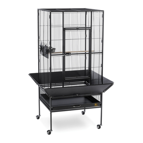
✩Your cage s now fully assembled!
3Install the s des:
The upper side (L2) & (R2) panels:
→slide down into channels along the
inside rails of the front and back
panels (see fig.3-1)
→have a center vertical wire extending
beyond the top and bottom horizontal
wires (see fig.3-2)
*The cup door locks on the (L2) panel
should be facing out
Slide the left s de upper (L2) panel
into place, making sure the panel is
centered within all channels. Align the
lower extended vertical wire with the
hole on the top edge of the (L1) rail.
Repeat the installation steps for the
r ght s de upper (R2) panel.
4Install the roof:
The center top (C) panel:
→has two vertical wires extending
beyond the top and bottom
horizontal wires
→has one small hole centered on
the underside of each side rail
Align the two extended vertical
wires on the center top (C) panel
with the two corresponding holes
on the inside rails of the (F) & (B)
panels (see fig.4-1).
Align the underside holes on
the center top (C) panel side rails
with the extended vertical wires on
(L2) & (R2) panels (see fig.4-2).
hen all extended wires and corresponding
holes are aligned, secure the center top (C)
panel with a long hex screw in each corner.
G
T
SG4
SG1
SG2
SG3
L2 R2
C
SG2
SG1
SG3
SG4
(fig.5-1)(fig.3-1)
(fig.3-2)
(fig.4-1)
(fig.4-2)
(fig.5-2)
(fig.6)


