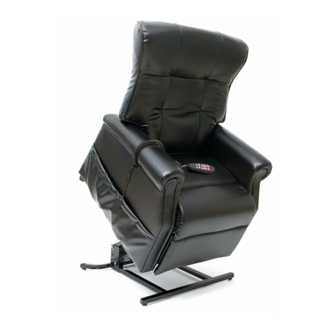
Pride Wallhugger 805 User manual

LIFT CHAIR
The Ultimate in Comfort & Style!
1-800-800-8586 (US) 1-888-570-1113 (Canada)

SAFETY GUIDELINESSAFETY GUIDELINES
SAFETY GUIDELINES
LIFT CHAIR
NOTE: This owner’s manual is compiled from the latest specifications and product information
available at the time of publication. We reserve the right to make changes as they become neces-
sary. Any changes to our products may cause slight variations between the illustrations and
explanations in this manual and the product you have purchased. The latest/current version of
this manual is available on our website.
The symbols below are used throughout this owner's manual and on the product to identify warnings and
important information. It is very important for you to read them and understand them completely.
WARNING! Indicates a potentially hazardous condition/situation. Failure to follow
designated procedures can cause either personal injury, component damage, or
malfunction. On the product, this icon is represented as a black symbol on a yellow
triangle with a black border.
MANDATORY! These actions should be performed as specified. Failure to perform
mandatory actions can cause personal injury and/or equipment damage. On the
product, this icon is represented as a white symbol on a blue dot with a white
border.
PROHIBITED! These actions are prohibited. These actions should not be performed
at any time or in any circumstances. Performing a prohibited action can cause
personal injury and/or equipment damage. On the product, this icon is represented
as a black symbol with a red circle and red slash.
Copyright © 2007
Pride Mobility Products Corp.
INFMANU2628/Rev E/October 2007
Please fill out the following information for quick reference:
Pride Provider:____________________________________________________________________
Address:_________________________________________________________________________
Phone Number:__________________________
Purchase Date:__________________________ Serial Number:____________________________

Lift Chair www.pridemobility.com 3
LIFT CHAIR
LABEL INFORMALABEL INFORMA
LABEL INFORMATIONTION
TIONTION
TION
PRODUCT SAFETY SYMBOLS
The symbols below represent labels used on the product to identify warnings, mandatory actions, and prohib-
ited actions. It is very important for you to read and understand these symbols completely. Do not remove
these labels from your product. Please note that not all of the symbols may be used on your lift chair model.
Pinch/Crush Points Hazard! Do not place objects or appendages in the path of
moving parts.
Read and follow the information in the owner’s manual.
Maximum weight capacity
Do not connect an extension cord to the AC/DC converter or the battery
charger.
Electrical Hazard
Removal of grounding prong can create electrical hazard. If necessary,
properly install an approved 3-pronged adapter to an electrical outlet having
2-pronged plug access.
Properly dispose of all electronic components, including the external
transformer, hand control, batteries, actuator motors, and wiring. Contact your
authorized Pride Provider for more information.

4 www.pridemobility.com Lift Chair
LIFT CHAIR LABEL INFORMALABEL INFORMA
LABEL INFORMALABEL INFORMA
LABEL INFORMATIONTION
TIONTION
TION
Red LED indicates low battery voltage. Replace with new batteries when lit.
Not applicable to all models.
Battery Door Location
Green LED indicates power to the unit is on. Not applicable to all models.
Indoor Use Only. Avoid exposure to rain, snow, ice, salt, or standing water.
Maintain and store in a clean and dry environment.
Class II Equipment
Do not place objects under lift chair. Make sure area is clear of obstructions
including pets and small children during operation.
Degree of protection against electric shock.
This product has been tested and complies to IEC 60601-1-2.

Lift Chair www.pridemobility.com 5
LIFT CHAIR
TABLE OF CONTENTSTABLE OF CONTENTS
TABLE OF CONTENTS
SAFETY GUIDELINES ......................................................................................... 2
LABEL INFORMATION ......................................................................................... 3
I. INTRODUCTION................................................................................................ 6
SAFETY ..................................................................................................................................................................... 6
PURCHASER’SAGREEMENT ................................................................................................................................... 6
INFORMATIONEXCHANGE ........................................................................................................................................ 6
PRIDEOWNER’SCLUB............................................................................................................................................. 6
II. GENERAL GUIDELINES................................................................................... 7
MODIFICATIONS......................................................................................................................................................... 7
WEIGHTLIMITATIONS ................................................................................................................................................ 7
PINCH/CRUSHHAZARDS .......................................................................................................................................... 7
DEGREEOFPROTECTION/MODEOFOPERATION ................................................................................................. 7
STORAGEANDOPERATIONTEMPERATURES ........................................................................................................ 7
EMI/RFI....................................................................................................................................................................... 8
SHIPPINGAND DELIVERY......................................................................................................................................... 8
MOTORVEHICLETRANSPORT................................................................................................................................. 8
III. YOUR LIFT CHAIR .......................................................................................... 9
BODYCOMPONENTS................................................................................................................................................ 9
ELECTRICALCOMPONENTS....................................................................................................................................11
IV. ASSEMBLY/DISASSEMBLY........................................................................... 12
LIFTCHAIRSETUP ...................................................................................................................................................12
LIFTCHAIRPLACEMENT..........................................................................................................................................14
BATTERYINSTALLATION ..........................................................................................................................................14
LIFTCHAIRDISASSEMBLY ......................................................................................................................................16
V. OPERATION ................................................................................................... 17
OPERATIONPRECAUTIONS.....................................................................................................................................17
HANDCONTROLOPERATION ..................................................................................................................................17
VI. TROUBLESHOOTING ................................................................................... 20
545/555MOTORTIMING............................................................................................................................................20
FREQUENTLYASKEDQUESTIONS .........................................................................................................................20
VII. CARE AND MAINTENANCE ......................................................................... 22
FABRICCARE ...........................................................................................................................................................22
ELECTRONICSCARE ...............................................................................................................................................22
DISPOSALANDRECYCLING ....................................................................................................................................22
VIII. WARRANTY ................................................................................................ 23
APPENDIX ......................................................................................................... 24

6 www.pridemobility.com Lift Chair
LIFT CHAIR
SAFETY
WELCOME to Pride Mobility Products Corporation (Pride). The product you have purchased
combinesstate-of-the-artcomponentswith safety,comfort, and stylingin mind.We areconfident
the design features will provide you with the conveniences you expect during your daily activities.
Understanding how to safely operate and care for this product should bring you years of trouble
free operation and service.
Read and follow all instructions, warnings, and notes in this manual and all other accompanying literature
before attempting to operate this product for the first time. In addition, your safety depends upon you, as well
as your provider, caretaker, or healthcare professional in using good judgement.
If there is any information in this manual which you do not understand, or if you require additional assistance
for setup or operation, please contact your authorized Pride Provider. Failure to follow the instructions,
warnings, and notes in this manual and those located on your Pride product can result in personal
injury or product damage and will void Pride’s product warranty.
PURCHASER’S AGREEMENT
By accepting delivery of this product, you promise that you will not change, alter, or modify this product or
removeorrender inoperable orunsafeany guards, shields, orothersafety features of thisproduct;fail, refuse,
or neglect to install any retrofit kits from time to time provided by Pride to enhance or preserve the safe use of
this product.
INFORMATION EXCHANGE
We want to hear your questions, comments, and suggestions about this manual.We would also like to hear
about the safety and reliability of your new lift chair, and about the service you received from your authorized
Pride Provider.Please notify us of any change of address, so we can keep you apprised of important information
about safety, new products, and new options that can increase your ability to use and enjoy your lift chair.
Please feel free to contact us at the address below:
USA:
Pride Mobility Products Corporation
Attn.: Customer Care Department
182 Susquehanna Ave.
Exeter, PA 18643-2694
customercare@pridemobility.com
1-800-800-8586
NOTE: If you ever lose or misplace your product registration card or your copy of this manual,
contact us and we will be glad to send you a new one immediately.
PRIDE OWNERS CLUB
As an owner of a Pride product, you are encouraged to enroll in the Pride Owners Club. Complete and return
your enclosed product registration card or visit Pride's web site at www.pridemobility.com.
From our home page, select “Owners Club” to enter a page dedicated to current and potential Pride product
owners. You will gain access to interviews, stories, recreation ideas, daily living tips, product and funding
information, and interactive message boards. These message boards invite you to communicate with other
Pride customers as well as Pride representatives who are available to assist you with any questions or
concerns.
I. INTRODUCTIONI. INTRODUCTION
I. INTRODUCTION
Canada:
Pride Mobility Products Company
380 Vansickle Road Unit 350
St. Catharines, Ontario L2R 6P7
1-888-570-1113

Lift Chair www.pridemobility.com 7
LIFT CHAIR
Your lift chair is a state-of-the-art life-enhancement device designed to increase mobility. Pride
provides an extensive variety of products to best fit your individual needs. Please be aware that
the final selection and purchasing decision regarding the type of lift chair to be used is the
responsibilityofyou,theliftchairuser,if capableof makingsuchadecision,and/or yourhealthcare
professional (i.e., medical doctor, physical therapist, etc.).
MANDATORY! Read and follow the information provided in this owner’s manual before
attempting to operate your lift chair for the first time.
There are certain situations, including some medical conditions, where you will need to practice operating the
lift chair in the presence of a trained attendant. A trained attendant can be defined as a family member or
healthcare professional specially trained in assisting you with performing various daily living activities while
safely operating a lift chair.
Below are some precautions, tips, and other safety considerations that will help you become accustomed to
operating the lift chair in a safe manner.
MODIFICATIONS
Pride has designed and engineered your lift chair to provide maximum comfort and utility.However, to prevent
personal injury and/or damage to your lift chair, you should not modify, add, remove, or disable any feature,
part, or function of your lift chair. Unauthorized modifications may also void your product’s warranty.
NOTE: Use Pride parts only for all repairs and replacements.
WEIGHT LIMITATIONS
Your lift chair is rated for a maximum weight capacity.Refer to the “Appendix A” for more information.
MANDATORY! Stay within the specified weight capacity of your lift chair. Pride will
not be held responsible for injuries and/or product damage resulting from failure to
observe weight limitations.
PINCH/CRUSH HAZARDS
The scissor and lift mechanisms are labeled as pinch/crush point hazards on your lift chair. Keep clear of
these areas and make sure the path of motion is unobstructed. See figure 3.1 for pinch/crush point locations.
WARNING! Do not place objects or appendages in the path of moving parts.
DEGREE OF PROTECTION/MODE OF OPERATION
!Class II equipment/Type B protection against electric shock
!Degree of protection against the ingress of solid/liquids (splash proof)—IPX4
!Mode of operation—Maximum Duty Cycle: 2min ON/18min OFF
STORAGE AND OPERATION TEMPERATURES
!Transportation or storage: -104°F/-75°C to 158°F/70°C
!Operation: 50°F/10°C to 104°F/40°C
II. GENERAL GUIDELINESII. GENERAL GUIDELINES
II. GENERAL GUIDELINES

8 www.pridemobility.com Lift Chair
LIFT CHAIR II. GENERAL GUIDELINESII. GENERAL GUIDELINES
II. GENERAL GUIDELINESII. GENERAL GUIDELINES
II. GENERAL GUIDELINES
ELECTROMAGNETIC AND RADIO FREQUENCY INTERFERENCE (EMI/RFI)
WARNING! Laboratory tests have shown that electromagnetic and radio frequency
waves can have an adverse affect on the performance of electrically-powered
devices, such as lift chairs.
Electromagnetic and Radio Frequency Interference can come from sources such as cellular phones, mobile
two-way radios (such as walkie-talkies), radio stations, TV stations, amateur radio (HAM) transmitters, wire-
less computer links, microwave signals, paging transmitters, and medium-range mobile transceivers used by
emergency vehicles. In some cases, these waves can cause unintended movement or damage to the control
system of electricaly-powered devices. Every electrically-powered device has an immunity (or resistance) to
EMI.The higher the immunity level, the greater the protection against EMI. Per EMC standards, this product
has passed immunity testing and is suitable for use in all establishments, including domestic establishments.
WARNING! Be aware that cell phones, two-way radios, laptops, and other types of
radio transmitters may cause unintended movement of your electrically-powered
device due to EMI. Exercise caution when using any of these items while operating
your lift chair.
WARNING! The addition of accessories or components to the lift chair can increase
the susceptibility of the chair to EMI. Do not modify your lift chair in any way not
authorized by Pride.
WARNING! Your lift chair itself can disturb the performance of other electrical devices
located nearby, such as alarm systems.
NOTE: If unintended motion occurs, discontinue use of the lift chair. Call Pride to report the incident.
SHIPPING AND DELIVERY
Before using your lift chair, make sure your delivery is complete as some components may be individually
packaged. If you do not receive a complete delivery, please contact your authorized Pride Provider immedi-
ately. Where damage has occurred during transport, either to the packaging or content, please contact the
delivery company responsible.
MOTOR VEHICLE TRANSPORT
If you will be transporting your lift chair in a motor vehicle, individual components (external transformer, etc.)
should be secured against slipping. The lift chair itself must also be secured against slipping (a possible
hazard during vehicle braking).

Lift Chair www.pridemobility.com 9
LIFT CHAIR
BODY COMPONENTS
This section describes the features of your lift chair.Carefully review the function and location of
each item described, and note that the illustrations and option locations shown in this manual
may not reflect the type of lift chair that you own.
III. YOUR LIFT CHAIRIII. YOUR LIFT CHAIR
III. YOUR LIFT CHAIR
Figure 3.1 Pride Lift Chair Main Components
HEAD COVER
HAND CONTROL
REMOVABLE
CHAISE PAD
REMOVABLE BACK PAD
ARM COVER
EXTERNAL
TRANSFORMER
LIFT MECHANISM
(PINCH POINT)
LEG LEVELERS (FOUR TOTAL)
SCISSOR MECHANISMS
(PINCH POINT)
POWER
CORD
LOW VOLTAGE
CONNECTION
CABLE STRAIN
RELIEF
LOW VOLTAGE
CONNECTION CABLE
BATTERY
DOOR
QUICK
RELEASE

10 www.pridemobility.com Lift Chair
LIFT CHAIR III. YOUR LIFT CHAIRIII. YOUR LIFT CHAIR
III. YOUR LIFT CHAIRIII. YOUR LIFT CHAIR
III. YOUR LIFT CHAIR
Removable Back Pad: Attaches to the lift chair with reusable fasteners to enable the use of the bed option on
some models and to make servicing the chair more convenient.
Removable Chaise Pad: Attaches to the lift chair with reusable fasteners to make servicing the chair more
convenient.
NOTE: The chair must be in the recline position in order to remove or attach the back pad, chaise
pad, or bed option mattress.
NOTE: The DMR 670 bed option consists of a mattress, bedsheet, strap, and storage bag. After
removing the mattress, it is recommended that you store it in the bag provided.
NOTE: If your lift chair is equipped with a removable back pad and/or chaise pad and has the
options of heat, heat and massage, or deluxe heat and massage, the back pad and/or chaise pad
can be removed without disconnecting the heating unit by detaching the white clip located on the
heat and massage wire. The TMR 450 Lift Chair has a clip for both heating units.
Lift Mechanism: Responds to the hand control commands to position the chair in the sit, recline, and stand
positions.
Leg Levelers: Manually rotate up or down in order to stabilize the chair before use (Fig. 3.2).
Figure 3.2 Leg Levelers
Scissor Mechanisms: Extend or retract to take the
chair through the various stages of recline (Fig. 3.3).
WARNING! Be aware that the
scissor mechanisms are a pinch
point on the lift chair. Keep
appendages and objects clear of
these points when operating the
footrest.
Figure 3.3 Scissor Mechanism
ROTATE CLOCKWISE TO LOWER THE CHAIR. ROTATE COUNTERCLOCKWISE TO RAISE THE CHAIR.
SCISSOR
MECHANISM
(PINCH POINT)

Lift Chair www.pridemobility.com 11
LIFT CHAIR
III. YOUR LIFT CHAIRIII. YOUR LIFT CHAIR
III. YOUR LIFT CHAIR
Footrest Extension: Provides5in. (13 cm)ofexten-
sionto thefootrest,increasingthe legsupportfortaller
individuals when the chair is in the recline position
(Fig.3.4).This feature is specific to the TMR 575 Lift
Chair and optional to theTMR 570 Lift Chair.
NOTE:The footrest extension folds up neatly and
is not visible when the chair is in the seated and
lift positions.
ELECTRICAL COMPONENTS
Your Pride Lift Chair is equipped with a low voltage
DC motor system that reduces the standard house-
holdalternating currentof110/115V AC(220/230/240
V AC) to direct current (24/39V DC). The electrical
components include the external transformer, batter-
ies, and hand control. Keep these areas free from
moisture at all times.
ExternalTransformer: Connects to a standard elec-
trical outlet to provide power to the lift chair. Some
transformers are equipped with colored LEDS—red
indicates low battery power and green indicates that
power to the transformer is on.
Theexternaltransformermayalsocomeequippedwith
a molded portion that allows the transformer to be
mounted to the wall directly under the standard outlet.
The screws must be mounted to the wall stud for se-
curity. Refer to “Appendix B”for a mounting diagram.
NOTE: Pride is not responsible for damage due
to improper installation.
Batteries: Provide the power needed to return the
lift chair from the recline position to the sit and/or lift
position in the event of a power failure.The batteries
are located inside the external transformer.
Hand Control: Contains the controls needed to
operate the various functions of the lift chair. Refer
toV.“Operation”for more information.The hand con-
trol may be equipped with a quick-release connec-
tor (Fig. 3.5) which enables the user to detach the
hand control from the chair, disabling all functions of
the hand control.
Figure 3.4 Footrest Extension
FOOTREST EXTENSION
(PINCH POINT)
Figure 3.5 Quick-Release Connector

12 www.pridemobility.com Lift Chair
LIFT CHAIR IVIV
IVIV
IV. ASSEMBL. ASSEMBL
. ASSEMBL. ASSEMBL
. ASSEMBLY/DISASSEMBLY/DISASSEMBL
Y/DISASSEMBLY/DISASSEMBL
Y/DISASSEMBLYY
YY
Y
Your lift chair may require some assembly before initial use. It may also require disassembly to
make servicing the chair more convenient. If your lift chair is a Knock-Down (KD) model, follow
the instructions in “Lift Chair Setup.” If your lift chair is not a KD model, proceed to “Lift Chair
Placement.”
LIFT CHAIR SETUP
KD models will arrive in the knock-down position (Fig. 4.1).
Figure 4.1 Knock-Down (KD) Position
Follow these steps to assemble the lift chair:
4.1.1. Remove the packaging from the back portion
of the chair and check that the locking clip is in
the vertical position.Reposition if necessary.
4.1.2. Slidethe leftandright KDsleevesof thechair-
back onto the KD connections on the arms
and seat of the chair.
LOCKING CLIP
KD CONNECTION
KDSLEEVE

Lift Chair www.pridemobility.com 13
LIFT CHAIR
IVIV
IVIV
IV. ASSEMBL. ASSEMBL
. ASSEMBL. ASSEMBL
. ASSEMBLY/DISASSEMBLY/DISASSEMBL
Y/DISASSEMBLY/DISASSEMBL
Y/DISASSEMBLYY
YY
Y
NOTE: Depending on chair width, you may need to slide on one side of the chair-back at a time. If
this is the case, level the chair-back before pressing down to lock into position.
4.1.3. Pushfirmly on thetop of thechair-back to lock
into position. Listen for a click on each side to
ensure the chair-back is locked in properly.
NOTE: Pull up on the chair-back to ensure that
it is locked in place. If the back can be pulled
off, then repeat steps 4.1.1 through 4.1.3.
4.1.4. Ifyour chairisequipped withheat and/ormas-
sage options, connect the quick-release con-
nections on the chair-back at this time.
NOTE: The heat connection is labeled while the
massage connection is not. The 450 and C30
model lift chairs come standard with two heat
pads. The upper massage unit on KD deluxe heat
and massage chairs is labeled with a red A.
4.1.5. Attach the chair-back to the hook and loop
flaps on the bottom of the chair base.
MASSAGE
CONNECTION
HEAT
CONNECTION
“CLICK”

14 www.pridemobility.com Lift Chair
LIFT CHAIR IVIV
IVIV
IV. ASSEMBL. ASSEMBL
. ASSEMBL. ASSEMBL
. ASSEMBLY/DISASSEMBLY/DISASSEMBL
Y/DISASSEMBLY/DISASSEMBL
Y/DISASSEMBLYY
YY
Y
LIFT CHAIR PLACEMENT
Yourliftchairshould be placed near a standardelectrical outlet on dry,levelground wherethereisample room
to allow for proper operation. Pride recommends that you have the assistance of an attendant when position-
ing the lift chair to avoid the possibility of injury when lifting.
Follow these steps to position the lift chair in a safe manner:
1. Place the back of the lift chair 30 in. (76 cm) from the nearest obstruction while the chair is in the seated
position.This measurement may vary depending on model.
2. Adjust the leg levelers to stabilize the lift chair (Fig. 3.2).
3. Install the batteries into the external transformer.Refer to “Battery Installation” for more information.
4. Position the external transformer on the floor in an open, well-ventilated area where it will not be an ob-
struction, or if equipped, utilize the optional wall mount.
5. Position the low voltage connection cable where it will not be pinched between the frame and the lift
mechanism.
6. Connect the low voltage connection cable to the external transformer if it is not already connected.
7. Plug the power cord directly into the electrical outlet. Do not use an extension cord!
NOTE: If you discover a problem at any point during the setup and positioning of your lift chair,
stop and contact your authorized Pride Provider immediately. To avoid personal injury and/or prod-
uct damage, do not plug the unit into the electrical outlet until the problem is corrected and do
not attempt to fix electrical problems by yourself.
NOTE: For chairs with heat and massage options, the green light on the external transformer is lit
to indicate proper operation. The blinking red light indicates that no batteries are installed or
battery power is low.
BATTERY INSTALLATION
Your lift chair is equipped with a battery backup system that will activate during a power failure.The backup
system is powered by two 9V batteries (not included) that need to be installed into the external transformer.
Follow these steps to install the batteries:
1. Unplug the external transformer power cord from the electrical outlet.
2. Open the marked battery door on the external transformer.
3. Install two 9V batteries into the external transformer (Fig. 4.2 and 4.3).
4. Replace the battery door.
NOTE: Always make sure the external transformer is equipped with two fresh 9V batteries, since
the battery backup system does not recharge itself. Fresh batteries are defined as 9V alkaline
batteries that are replaced every time the battery backup system is activated during a power
failure, or once a year if the battery backup system has not been activated.
NOTE: If you unplug your lift chair for an extended period of time (more than one hour), remove the
batteries from the external transformer. The lift chair will draw power from the batteries even
when it is not in use.

Lift Chair www.pridemobility.com 15
LIFT CHAIR
IVIV
IVIV
IV. ASSEMBL. ASSEMBL
. ASSEMBL. ASSEMBL
. ASSEMBLY/DISASSEMBLY/DISASSEMBL
Y/DISASSEMBLY/DISASSEMBL
Y/DISASSEMBLYY
YY
Y
LOW VOLTAGE CONNECTION CABLE
POWER CORD
EXTERNAL TRANSFORMER
(TOP AND SIDE VIEW)
BATTERY DOOR
Figure 4.2 Standard Lift Chair Battery Location
Figure 4.3 Heat and Massage Lift Chair Battery Location (Including 555 model)
LOW VOLTAGE CONNECTION CABLE
POWER CORD
EXTERNAL TRANSFORMER
(BOTTOM VIEW)
BATTERY
LOCATION

16 www.pridemobility.com Lift Chair
LIFT CHAIR
LIFT CHAIR DISASSEMBLY
The back portion of KD Lift Chairs can be removed to make service and transport of the chair more
convenient.
Follow these steps to disassemble the lift chair:
IVIV
IVIV
IV. ASSEMBL. ASSEMBL
. ASSEMBL. ASSEMBL
. ASSEMBLY/DISASSEMBLY/DISASSEMBL
Y/DISASSEMBLY/DISASSEMBL
Y/DISASSEMBLYY
YY
Y
4.4.1. Remove the bottom of the back fabric from
the hook and loop flaps on the chair base. 4.4.2. If your lift chair is equipped with heat and/or
massage options, locate the quick-release
connections,grip theplastic ends,andpull the
connections apart. Avoid pulling on the wires
when making the disconnection.
4.4.3. Usingalarge flat-head screwdriver,liftthe left
and right locking clips on the chair-back one
side at a time to raise the back from the con-
nections on the chair base. As you lift each
locking clip, pull up on the chair-back to lift
that side over the lock.
MASSAGE
CONNECTION
HEAT
CONNECTION
4.4.4. Liftthechair-back up and awayfromthe chair
base.

Lift Chair www.pridemobility.com 17
LIFT CHAIR
OPERATION PRECAUTIONS
There are certain precautions that should be taken during the operation of your lift chair.Read and
follow these precautions carefully in order to ensure safe lift chair operation and to prevent injury
and/or product damage.
!Plug the power cord directly into the electrical outlet. Do not use an extension cord!
!Do not place anything (for example, a drinking glass) on top of or near the external transformer.
!If the external transformer box or hand control requires cleaning, unplug the power cord from the electrical
outlet and use a clean, dry cloth or lightly dampened cloth. Allow ample drying time before plugging the
power cord back into the electrical outlet.
!Periodically check the hand control and all power cords for visible damage.
!Keep the hand control away from all heated surfaces.
!Ensure the hand control is out of the way before sitting in the chair.
!Keep children and pets away from all moving parts while operating the lift chair.
!Do not allow children to play on or operate the lift chair.Only the intended user should operate the lift chair.
!Avoid pinch points, such as the lift and scissor mechanisms.Keep hands and feet clear of these areas.
!Always leave the chair in an upright and closed position when not in use.
!Do not sit or stand on the footrest or the extended footrest.
!Do not “drop” into the lift chair when sitting if it is in a partially raised position.
PROHIBITED! Do not place objects under the lift chair. Make sure area is clear of
obstructions including pets and small children during operation.
WARNING! Prevent the risk of electrical shock, fire, falls and/or being pinched. Follow
all instructions provided.
HAND CONTROL OPERATION
Depending on lift chair model, the hand control may be equipped with switches that control the movement of
the chair-back, chair base, and footrest, as well as the heat and massage options (Fig. 5.1 and 5.2).
NOTE: For the DMR/Infinite Series Lift Chairs, move the lift/recline switch (Fig. 5.3) to the “lift” posi-
tion before raising your chair. On the deluxe heat and massage hand control, this is a push button
located above the toggle switch. A green LED will indicate whether you are in lift or recline mode.
NOTE: Heat and massage functions will be temporarily shut down when using the hand control to
change lift chair position. Normal function will return when the motion stops.
Follow these steps to sit in your lift chair (Fig. 5.1):
1. Engage and hold the up/down switch in the UP position to raise your lift chair to the standing position.
2. Back into the lift chair and sit in the center of the seat, using the armrests for support if needed.
3. Engage and hold the up/down switch in the DOWN position to lower the lift chair to a comfortable seated
position.
Follow these steps to recline your lift chair from the seated position (Fig. 5.1):
1. Engage and hold the up/down switch in the DOWN position until comfortably reclined.
2. Engageand holdtheup/down switchinthe UP positiontoreturn toanupright, seated position.Releasethe
switch when the lift chair reaches a comfortably seated position.
Follow these steps to stand up from your lift chair (Fig. 5.1):
1. Engage and hold the up/down switch in the UP position to raise your lift chair.
2. Release the switch when the lift chair reaches a height where you can stand up comfortably.
NOTE: To avoid personal injury, the DMR/Infinite Series models require that the lift chair be upright
in the seated position before raising it to the standing position.
VV
VV
V. OPERA. OPERA
. OPERA. OPERA
. OPERATIONTION
TIONTION
TION

18 www.pridemobility.com Lift Chair
LIFT CHAIR VV
VV
V. OPERA. OPERA
. OPERA. OPERA
. OPERATIONTION
TIONTION
TION
Follow these steps to activate/deactivate the
massage option (Fig. 5.2):
1. Slide the white massage switch to the ON posi-
tion to activate the massage option.
2. Slide the white massage switch to the OFF posi-
tion to deactivate the massage option.
Follow these steps to activate/deactivate the heat
option (Fig. 5.2):
1. Slide the red heat switch to the ON position to
activate the heat option.
2. Slide the red heat switch to the OFF position to
deactivate the heat option.
NOTE: Heat units are designed with an auto-
shutoff mechanism that turns off the heat af-
ter 15 minutes of use. To reactivate the heat
function, slide the red heat switch to the OFF
position and then back to the ON position.
NOTE: Pride recommends that the heat and
massage units not be used for more than 15
minutes at a time. However, you should consult
your physician about how often you should use
the heat and massage options on your lift chair.
Figure 5.1 Pride Lift Chair Standard Hand Control
Figure 5.2 Heat and Massage Hand Control
UP POSITION
DOWN POSITION
HEAT SWITCH ON
OFF
ON
OFF
MASSAGE
SWITCH
UP POSITION
DOWN POSITION
Figure 5.3 Infinite Series Hand Control
UP POSITION
DOWN POSITION
LIFT/RECLINE
SWITCH
LIFT POSITION RECLINE POSITION

Lift Chair www.pridemobility.com 19
LIFT CHAIR
VV
VV
V. OPERA. OPERA
. OPERA. OPERA
. OPERATIONTION
TIONTION
TION
Figure 5.4 Deluxe Heat and Massage Hand Control
UP/DOWN SWITCH PUSH BUTTON FOR INFINITE POSITION
CHAIRS (660, 670 MODELS ONLY)
RED HEAT (ON/OFF)
BLUE MASSAGE (ON/OFF)
BLUE MASSAGE INCREASE/
DECREASE (LOW/MED/HI)
BLUE MASSAGE MODE
(CONSTANT/PULSE/WAVE)
LED FOR LIFT/FOOTREST
(660, 670 MODELS ONLY)
LED FOR BACK/RECLINE
(660, 670 MODELS ONLY)
UP POSITION
DOWN POSITION
Follow these steps to activate the deluxe heat option:
1. Press the red heat on/off button to activate the deluxe heat option (Fig.5.4).The heat will shut off after 12-
15 minutes of continuous use.
Follow these steps to activate and adjust the deluxe massage option:
1. Press the blue massage on/off button to activate the deluxe massage option (Fig. 5.4).
2. Press the blue massage increase/decrease button until the desired massage intensity is selected (Fig.
5.4).
3. Press the blue massage mode button until the desired type of massage is selected (Fig. 5.4).
NOTE: The massage function will shut off after 12-15 minutes of continuous use.

20 www.pridemobility.com Lift Chair
LIFT CHAIR VI. TROUBLESHOOTINGVI. TROUBLESHOOTING
VI. TROUBLESHOOTINGVI. TROUBLESHOOTING
VI. TROUBLESHOOTING
Your Pride Lift Chair is a state-of-the-art product designed to enhance your mobility.Your lift chair
should bring you years of trouble-free service, however, it may require occasional troubleshooting.
The following troubleshooting tips and FAQs should summarize what you need to know about your
liftchair.If atanytimeyou donotfeelcomfortableperformingthe troubleshootingsteps listedinthis
manual, contact your authorized Pride Provider for service.Please have the model number, serial
number, and nature of the problem when calling.
FREQUENTLY ASKED QUESTIONS
What if my lift chair does not operate at all?
!Ensure the external transformer is plugged into a properly wired electrical outlet.
!Check the circuit breaker box connected to the electrical outlet.
!Ensure the low voltage connection cable is plugged into the external transformer.
!Ensure the hand control and motor(s) are plugged in properly.
!Ensure the low voltage connection cable is plugged into the motor(s).
!Movetheup/downswitch on the hand control to theUPand DOWN positions and listen for aclickingnoise
from the external transformer. For heat and massage models, the clicking noise comes from the motor
controlboxunderthe chair.If thereisno clickingnoise, thenthemotor is not receivingpowerfrom thehand
control and the hand control may have to be replaced. If you do hear a clicking noise, then there may be a
problemwiththe motor and itmayneed to be servicedorreplaced. Contact your authorizedPrideProvider
for further assistance.
What if my lift chair operates in one direction only?
!Check the up/down switch on the hand control to make sure there is a smooth movement from the UP
position to the DOWN position. If the switch is sticking in either position, the hand control may need to be
replaced.
!Movetheup/downswitch on the hand control to theUPand DOWN positions and listen for aclickingnoise
from the external transformer. If there is no clicking noise, then the motor may not be receiving power from
the hand control and the hand control may need to be replaced.
!Contact your authorized Pride Provider for further assistance.
What if my lift chair stops during a lifting cycle?
!Yourliftchair is equippedwithan internal thermalshutoff switch located insidetheexternal transformerthat
prevents the motor control box from overheating. If the thermal shutoff activates, allow the lift chair to
remain in a stationary position for 10 minutes to allow the motor to cool, then resume normal operation. If
you notice the motors overheating frequently, contact your authorized Pride Provider.
!There may have been a power failure and/or there are no batteries in the external transformer or the
batteries have no charge. Always make sure there are fresh 9V batteries in the external transformer.
!Check the circuit breaker box connected to the electrical outlet.
What if my lift chair is rocking from corner to corner after I position the chair?
Thefloormay be unevenorthe carpet maybeaffecting chair position. Adjustthe leg levelers inthearea where
the chair is rocking.See III.“Your Lift Chair” for instructions on leveling your chair.
What if the footrest and recline functions on my DMR/Infinite Series lift chair do not work
properly?
Make sure the switches on your hand control are at the proper settings.
Where can I place the external transformer box?
!On the floor in an open, well-ventilated area where it will not be an obstruction.
!On the wall utilizing the optional external transformer wall mount.
This manual suits for next models
4
Table of contents
Other Pride Indoor Furnishing manuals
Popular Indoor Furnishing manuals by other brands

Regency
Regency LWMS3015 Assembly instructions

Furniture of America
Furniture of America CM7751C Assembly instructions

Safavieh Furniture
Safavieh Furniture Estella CNS5731 manual

PLACES OF STYLE
PLACES OF STYLE Ovalfuss Assembly instruction

Trasman
Trasman 1138 Bo1 Assembly manual

Costway
Costway JV10856 manual