Primacoustic MaxTrap User manual
INSTALLATION MANUAL
MaxTrap
Congratulations on purchasing the MaxTrap from Primacoustic. The MaxTrap is an easy to
assemble bass trap that will effectively absorb a wide bandwidth of frequencies and look great
for years to come. Please take a few minutes to read through this assembly manual. It will give
you a list of included parts, as well as step by step assembly and wall mounting instructions.
Please refer to www.primacoustic.com for various placement options, benets, and general
room acoustics information. Should you have any questions or comments, we invite you to
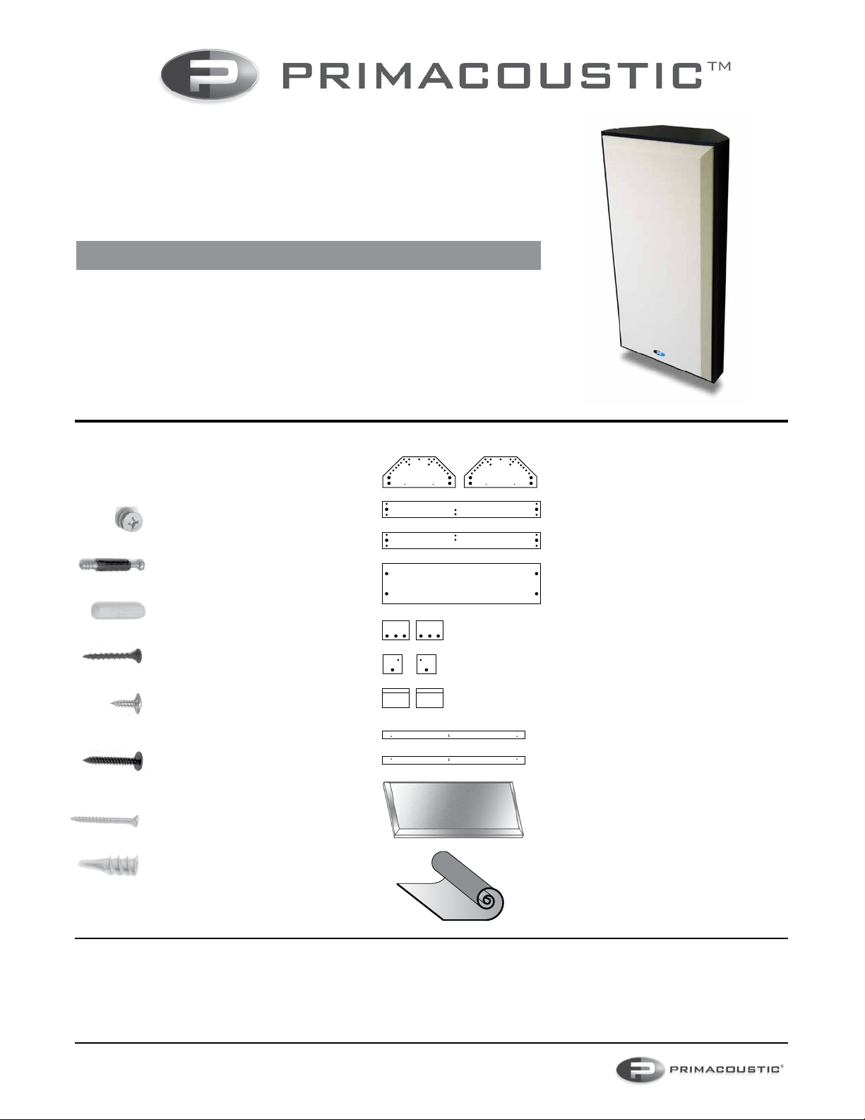
BOX CONTENTS:
Before beginning assembly, please take a
moment to familiarize yourself with the box
contents.
(QTY) Description:
(1) Black ‘Top’ section
(1) Black ‘Bottom’ section
(2) 48” Black side sections
(1) 48” Back section
(2) Beveled Stretchers
(2) Support Blocks
(2) Beveled Wall Cleats
(2) 46” Panel Stops
(1) Fabric wrapped acoustic panel
(1) Loaded vinyl barrier
Warranty: Please inspect panels immediately after purchase and before mounting. Primacoustic Broadway acoustic panels are guaranteed to be free of manufacturing defects for a period of thirty (30) days after purchase. In the unlikely
event that a defect is uncovered, please call 604-942-1001 to obtain an RA number (Return Authorization number) from Primacoustic before the thirty (30) day warranty period expires. Once you have obtained an RA number you must
return the product, freight prepaid, within fteen (15) days after the date the RA number is issued. Please return the product in the original packaging (or another, affording an equal degree of protection) with all of the following: (1) RA
number clearly marked on the returned package; (2) a receipt or bill of sale showing proof of purchase from an authorized retail seller; and (3) a written note describing the defect and including your name, address, telephone number
and the applicable RA number. You are solely responsible for all shipping and insurance costs for returning the product to Primacoustic, and you will not be reimbursed or compensated for any loss or damage incurred during return
shipping. Primacoustic will at its discretion repair or replace the panel. Should the panel be no longer available, Primacoustic reserves the right to exchange this with a panel of similar performance and value. Due to different dye lots,
Primacoustic cannot guarantee exact color match. This Warranty shall solely extend to the original owner and is limited to manufacturing defects and excludes any damage due to wear and tear, abuse, misuse, misapplication, color
fading or deterioration due to prolonged exposure to ultra violet light, smoke, humidity or other environmental factors. It is understood that the use and suitability of Broadway is entirely the responsibility of the buyer or specifying engineer
and as such, these parties agree to hold Primacoustic, or it’s associated company, and/or ofcers, harmless from any responsibility whatsoever other than what is clearly outlined in this warranty.
46” PANEL STOPS
LOADED VINYL
FABRIC COVERED
ACOUSTIC PANEL
48” SIDES
TOP BOTTOM
BACK
BEVELED WALL CLEATS
SUPPORT BLOCKS
BEVELED STRETCHERS
HARDWARE BAG CONTENTS:
(QTY) Description:
(20) Cam-locks
(20) Cam-pins
(14) Wooden dowels
(10) Medium Phillips screws
(8) Short Phillips pan-head
screws
(2) Long Phillips pan-head
screws
(4) Heavy duty Phillips screws
(4) Plastic drywall anchors
TOOLS REQUIRED:
- Large Phillips head screwdriver
- Hammer or mallet
- Bubble Level
- Cordless Drill
- Wall Stud nder (recommended)
Primacoustic is a division of Radial Engineering Ltd.
1588 Kebet Way, Port Coquitlam, BC Canada V3C 5M5
Tel: (604) 942-1001 • Fax (604) 942-1010 • [email protected]
www.primacoustic.com
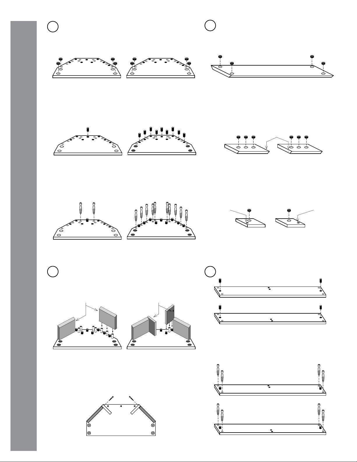
Push two wooden dowels into each 48” side section.
1
With a Phillips head screwdriver, screw ten cam-pins into
the small pre-drilled holes on the top section and two into
the bottom section as indicated below.
2
34
Push four cam-locks into the 48” back section.
Ensure the open side of the cam-lock (marked with
an arrow head on the cam) is facing toward the
edge so it can mate with the cam-pin.
BACK SECTION
Push the beveled stretchers and support blocks onto the
cam-pins and dowels. Note the orientation of the small pilot
holes. These need to line up so the stretcher and support
block can be screwed together.
Screw four cam-pins into each 48” side section.
LEFT
LEFT
RIGHT
RIGHT
BOTTOM TOP
BOTTOM TOP
Place the top and bottom sections on the oor with
the pre-drilled holes facing up. Push four cam-locks
into each top and bottom section. Ensure the open
side of the cam-lock (marked with an arrow head on
the cam) is facing toward the edge so it can mate with
the cam-pin.
Push nine wooden dowels into the top section and
one into the bottom section as indicated below. Tap
lightly with hammer if necessary.
BOTTOM TOP BEVELED STRETCHERS
Push three cam-locks into each beveled stretcher.
Note the small pilot hole drilled in the edge of each
beveled stretcher. These will be used in the next
step.
Pilot
Holes
Push one cam-lock into each support block. Note
the small pilot hole on the top of each block. These
will be used in the next step.
SUPPORT BLOCKS
Pilot
Hole
Pilot
Hole
TOP
Pilot Holes
TOP TOP
Pilot Holes
Tighten all cams snugly using a Phillips screwdriver.
Drive a medium Phillips head screw through the pilot holes on
each support block and beveled stretcher.
www.primacoustic.com
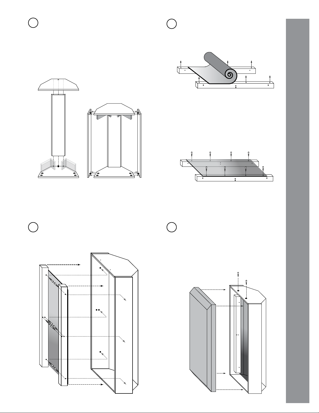
Set the 48” back section onto the top assembly
being careful to line up the cam-pins and dowels.
Tighten all cams snugly using a Phillips screwdriver.
Set the bottom section onto the back section and
tighten the cams.
Rotate the frame so it is up-side-right.
Attach the 48” sides being careful to line up the
cam-pins and dowels. Tighten the cams.
56Set the two panel stops on their edge with the four
small pilot holes facing up. Lay the vinyl material on
top of the panel stops.
7Set the vinyl barrier and panel stop assembly
into the frame. Attach the panel stops using eight
medium Phillips screws into the pre-drilled hole
locations on the inside of the 48” side sections.
8Push the Broadway acoustic panel into the front
of the frame assembly. The panel should t
snugly inside the frame. Do not force the panel
into place.
Fasten the Broadway panel with two Phillips
pan-head screws through the pre-drilled holes
in the top section. This will prevent accidental
dislodgment of the panel.
Line up the edges ush and square. Drive eight
short Phillips pan-head screws through the vinyl
into the small pilot holes. Avoid stretching the vinyl
between screws. It should lay at and limp.
TOP BOTTOM
TOP
BOTTOM
LEFT
RIGHT
www.primacoustic.com
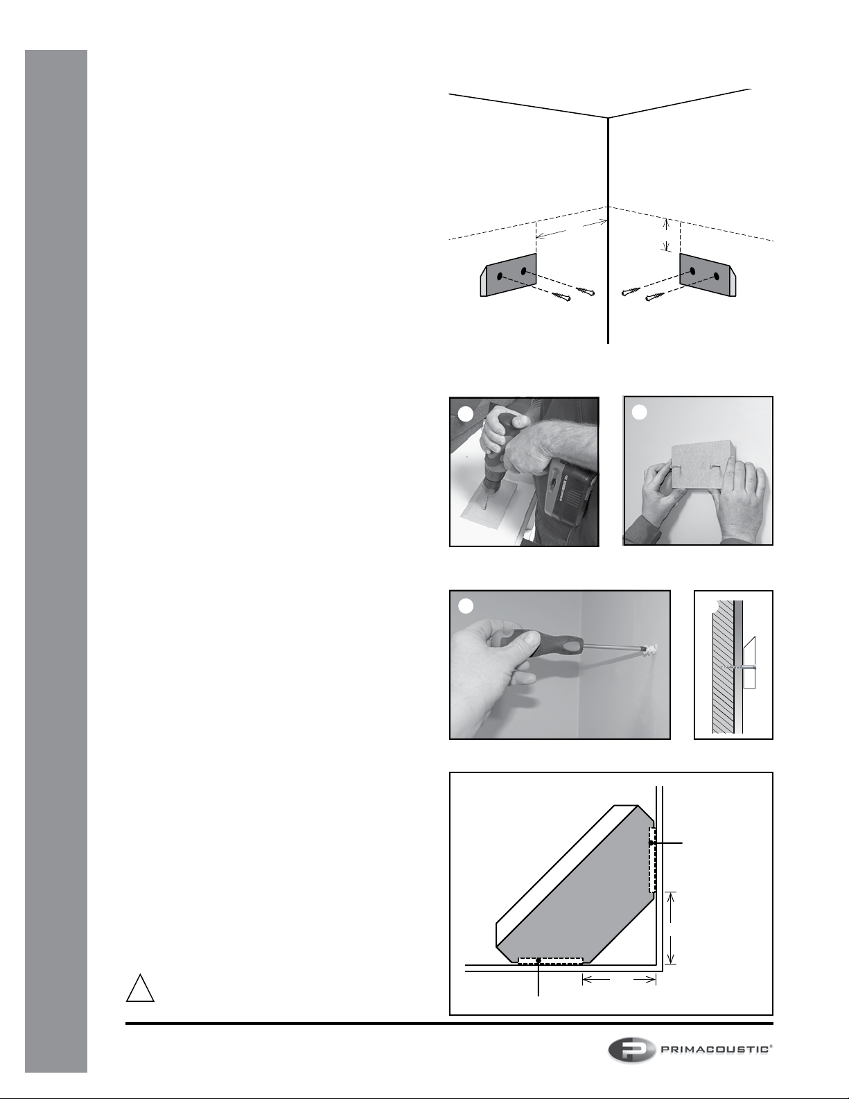
WALL MOUNTING INSTRUCTIONS
Select the corner where you would like to hang your
MaxTrap. Ideally, the center of the MaxTrap should be
placed at the same height as your ears when seated in
your listening position but this is exible if room décor or
listening position dictates otherwise.
uUse a bubble level and pencil to make two horizontal
lines out from the corner where you want the top of the
MaxTrap to be.
vMeasure out from the corner 8.5 inches and mark a
vertical line. This line represents the edge of the beveled
wall cleat that will be closest to the corner.
wFrom the top line measure down 3.75 inches and mark
a short horizontal line. This line represents the top of the
beveled wall cleat.
uv w u
3.75”
8.5”
Pre-drill two 1/8” holes in each beveled wall cleat. Drive
two heavy duty Phillips screw into each wall cleat so the
tips of the screws slightly protrude. This will help tto mark
the plastic anchor locations in the next step.
Line the beveled wall cleats up with the lines you
marked on the wall in steps 2 and 3. Press the screw tips
into the wall to mark the positions for the plastic drywall
anchors.
Push the four plastic anchors into the wall where you
marked in step 5. Tap lightly with a hammer to drive the
anchor in and screw the plastic anchor ush to the wall.
Screw the beveled wall cleats into the plastic anchors.
Ensure the beveled edge is on top and facing the wall as
shown in the diagram.
With the help of a second person, lift the completed
MaxTrap assembly up and gently rest the back of the
Maxtrap down onto the beveled wall cleats. The beveled
edges on the stretchers and cleats will lock together and
safely support the MaxTrap.
8.5”
8.5”
Beveled Wall Cleat
Beveled Wall Cleat
WARNING: The installation methods outlined are
recommendations only. Please seek professional
advice if you are unsure about any of these methods.
!
Primacoustic is a division of Radial Engineering Ltd.
1588 Kebet Way, Port Coquitlam, BC Canada V3C 5M5
Tel: (604) 942-1001 • Fax (604) 942-1010 • [email protected]
MaxTrap manual Part #: R870 2032 00 / 03-2017


