Prime Security PrimeStart 650 User manual

PrimeStart 650 Installation Manual

PrimeStart 650 Installation Manual

PrimeStart 650 Installation Manual
Table of Contents
Important Information...........................2
Recommended Installation Tools....................2
Recommended Procedures.......................2
Wiring Diagrams............................3
Pin Connectors.............................6
Installation Procedures...........................8
Control Unit...............................8
RangeMaster™ Super Heterodyne Receiver Module...........8
Wireloom ................................8
LED Indicator..............................9
Valet Switch...............................9
Zone
2
™ Impact Sensor.........................9
Additional Sensor Input.........................9
Alarm Armed Signal (-) Output.....................9
Brake Lights (Mandatory)........................10
Parking Lights.............................10
Reverse Light..............................10
Interior Light Illumination.......................11
Channel 2 Accessory Output (Trunk Release)..............11
Channel 6 Accessory Output......................11
Channel 9 Accessory Output......................11
Remote Start Armed Signal (-) Output.................11
Factory Alarm Disarm (-) Output....................12
Accessory Remote Start (-) Input....................12
Trunk Switch..............................12
Ignition Switch Connections......................12
Remote Engine Start Neutral Safety Switch Bulletin ..........14
Door Lock/Unlock...........................17
Door Lock Diagrams..........................17
Tach Wire (RPM Monitoring)......................21
Hood Switch (Mandatory) .......................21
Siren..................................22
Power and Ground Connections....................22
Mandatory RPM Programming.....................23
Programmable Features..........................24
Programming Table for System Features................25
Programming Table for Remote Controls................26
1

Important Information
Recommended Installation Tools
Voltmeter
Wire Strippers
Electric Drill & Bits
Phillips Screwdriver
Convoluted Tubing *
Solder Gun *
Wire Crimpers
Shrink Tube or Electrical Tape* Optional
Recommended Procedures
1.Test all circuits with a voltmeter.
2.Make all wiring connections with the supplied solderless crimp
connectors. DO NOT twist wires or use scotch-lok connectors.
3.Route the small and large RED, RED/WHITE and BLACKwires from the
control unit directly to the battery.
4.Keep extensions as short as possible. Use same gauge wires for short
extensions and larger gauge wires for longer extensions.
5.Before installing, discuss the placement of the LED indicator and valet
switch with the vehicle owner.
6.DO NOT disconnect the battery cables. Make all connections by
removing the bolts from the cable clamps without detaching the clamp.
7.Turn off dome light or remove dome light fuse to prevent battery drain.
This device complies with Part 15 of the FCC rules. Any changes or modifications
made to the system without the express approval of Prime Security, Inc. could
void the user’s authority to operate this equipment.
2
PrimeStart 650 Installation Manual
3
PrimeStart 650 Installation Manual
Main Wiring Diagram - 16 Pin

Main Wiring Diagram - 12 Pin
4
PrimeStart 650 Installation Manual
5
PrimeStart 650 Installation Manual
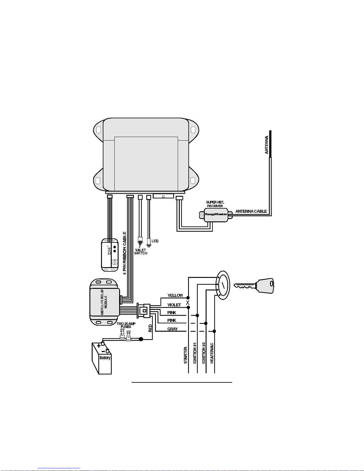
Satellite Relay Module Diagram

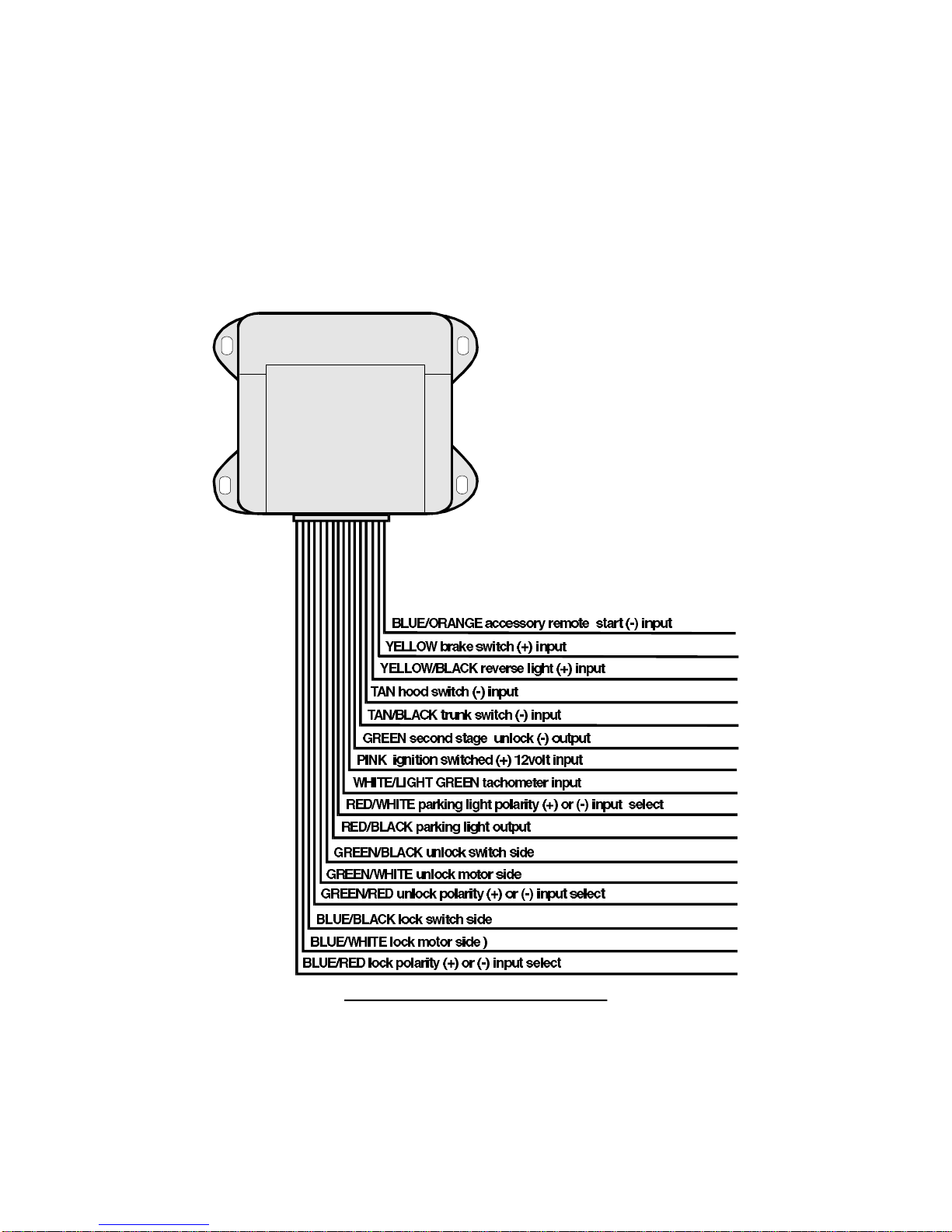
16 Pin Connector
Pin NumberWire ColorDescription
1BLUE / ORANGEAccessory Remote Start (-) Input
2YELLOWBrake Switch (+) Input
3YELLOW / BLACKReverse Light (+) Input
4TANHood Switch (-) Input
5TAN / BLACK Trunk Switch (-) Input
6GREENSecond Stage Unlock (-) Output
7PINK Ignition Switched +12 Volt Input
8WHITE / LIGHT GREENTachometer Input
9RED / WHITEParking Light Polarity Input (+) or (-) Select
10 RED / BLACKParking Light Output
11 GREEN / BLACKUnlock Switch Side
12 GREEN / WHITE Unlock Motor Side
13 GREEN / REDUnlock Polarity (+) or (-) Select
14 BLUE / BLACKLock Switch Side
15 BLUE / WHITELock Motor Side
16 BLUE / REDLock Polarity (+) or (-) Select
12 Pin Connector
Pin NumberWire ColorDescription
1GRAY Alarm Armed Signal (-) Output
2GRAY / BLACKRemote Start Activated (-) Output
3GRAY / WHITEFactory Alarm Disarm (-) Output
4DARK BLUEChannel 2 (-) Output (Trunk Release)
5LIGHT BLUEChannel 6 (-) Output
6BLUE / YELLOWChannel 9 (-) Output
7REDBattery (+)
8WHITE Door Trigger
9VIOLET Siren (-) Output
10WHITE / BLACKDoor Trigger Input Polarity (+) or (-) Select
11 BLACKBattery (-)
12 ORANGEOptional Sensor (-) Input
6
PrimeStart 650 Installation Manual

6 Pin Connector
Pin NumberWire ColorDescription
1YELLOWStarter Interrupt Switch Side
2GRAYHeater / AC Output
3VIOLETStarter Interrupt Starter Side
4PINKIgnition Output
5RED Battery (+)
6PINKIgnition Output
7
PrimeStart 650 Installation Manual

Installation Procedures
Control Unit
1.Select a location under the dash that will allow you to use the tie wraps to
securely fasten the control unit.
2.Mount the control unit as high as possible to ensure maximum security.
3.Do not mount the control unit near moving parts.
4.Avoid areas that are in the direct path of air blowing from the vents.
5.Route wires from this point, leaving slack for ease of service.
RangeMaster™ Super Heterodyne Receiver Module
1.Plug the receiver module WHITEconnector into the control unit WHITE
plug.
2. Use tie wraps to fasten the receiver module as far from the control unit as
possible.
3.Route the antenna cable behind the driver side windshield pillar, above
the headliner and behind the rear view mirror.
4.Fasten the antenna to the windshield with the attached adhesive tape.
Attach the antenna vertically so that the rubber tip on the end of the
antenna is facing downward.
Wireloom
1. Plug the wirelooms securely into the control unit and satellite relay
module.
2.Route wires from the control module and satellite relay module directly to
each connection point.
3.Separate the small and large RED , RED/WHITE, BLACK, TAN, VIOLET
and WHITE/GREENwires.
4.Sleeve these wires with vinyl tubing or electrical tape and route them
through an existing rubber grommet into the engine compartment.
5.If an existing grommet is not available, drill a hole and install a snap
grommet.
8
PrimeStart 650 Installation Manual

LED Indicator
1.Discuss placement with the owner.
2. Choose a location that is visible from both sides of the vehicle.
3.Drill a ¼" hole.
4. Route the LED wires through the hole and press LED into place.
5.Route the LED wires to the control unit.
6.Plug the REDLED connector into the control unit REDplug.
Valet Switch
1.Discuss placement with the owner.
2. Choose a location for the valet switch that is hidden, but convenient for
the owner to access.
3.Drill a ¼" hole and mount the switch.
4. Route the valet switch wires to the control unit.
5.Plug the valet switch WHITEconnector into the control unit WHITE plug.
Zone2
™ Impact Sensor
The sensor must be firmly mounted on a solid metal surface inside the vehicle.
We recommend tie wrapping the sensor to the steering column housing or
steering column support bracket. DO NOT mount the sensor near moving
parts or in the direct path of an air duct opening.
1.Plug the impact sensor BLUE 4-pin connector into the control unit BLUE
4-pin connector.
2. Route the impact sensor harness to the chosen mounting location.
3.Using the long tie wraps supplied, securely fasten the impact sensor
allowing access to the adjustment screws.
Additional Sensor Input
The ORANGEwire is a (-) trigger input with a 5 second arming delay. This
input can be used for optional sensors such a glass sensor, radar sensor or any
other type of sensor that provides a (-) ground output when triggered.
Alarm Armed Signal (-) Output
The GRAYwire will provide a continual 300 M.A. output whenever the alarm is
armed. This output can be used for voice modules, window roll-up modules and
anyotheroptionalaccessorythatrequiresa(-)outputwhenthealarmisarmed.
9
PrimeStart 650 Installation Manual

Brake Lights (Mandatory)
ICAUTION: As a safety feature, the unit monitors the brake light to
prevent an unauthorized driver from driving the car and to switch to
normal engine operating condition. For this reason, the YELLOW
brakelightinputwiremustbeconnectedand the brake lightmustbe
in working condition or the remote start will not operate properly.
1.Turn the ignition key to the "ON" position, then press the brake pedal and
make sure the brake light illuminates.
2.Use a voltmeter to find the one wire at the brake light switch (usually
located on the upper brake pedal arm) that shows +12 volts when you
press the brake pedal and 0 volts when the brake pedal is not depressed.
3. Connect the 18 ga YELLOWwire to the vehicle brake light switch wire.
Parking Lights
1.If the parking lights are positive trigger, connect the RED/WHITE wire to
the battery positive (+) terminal through the 20 amp fuse assembly.
NOTE:DonotconnecttheRED/WHITEwiretothecontrolunit RED wire.
2.If the parking lights are negative (-) trigger, connect the RED/WHITE wire
to control unit BLACK wire.
3.Connect the RED/BLACKwire to the vehicle parking light wire.
Reverse Light
ICAUTION: Some vehicles allow you to remove the gear shift
selector from "Park" even while the ignition key is not on. As a safety
feature, the system will monitor the reverse wire. If the vehicle is
removed from "Park" while in the remote start mode, the system will
shut down immediately.
1.Set the parking brake.
2.Turn the ignition key to the "ON" position and adjust the gear shift selector
to "Reverse."
3.Use a voltmeter to find the wire that will show +12 volts in "Reverse" and
0 volts in "Park."
4. Connect the YELLOW/BLACKwire to the vehicle’s reverse light wire.
10
PrimeStart 650 Installation Manual

Interior Light Illumination
1.Connect the WHITE wire to the vehicle door trigger wire.
2.If the door trigger is negative, connect the WHITE/BLACK wire to ground.
3. If the door trigger wire is positive switching, connect the WHITE/BLACK
wiretoafusedconstant +12voltsource.DonoteusethealarmREDwire.
Channel 2 Accessory Output (Trunk Release)
The DARK BLUEwire provides a 0.75 second ground output when the
TRUNK button is pressed for 1-2 seconds while the alarm is disarmed only. If
the TRUNK button is continually pressed, the output will stay at ground as
long as the button is held. Most factory trunk releases are positive trigger and
require an optional relay.
Channel 6 Accessory Output
The LIGHT BLUEwire provides a 0.75 second ground output when the
ARM/DISARM and SILENT buttons are pressed at the same time for 1-2
seconds. If the ARM/DISARM and SILENT buttons are continually pressed, the
output will stay at ground as long as the buttons are held. This output can be
used for optional accessories such as window roll-up/down or any other
accessory requiring a (-) input.
Channel 9 Accessory Output
The BLUE/YELLOWwire provides a 0.75 second output when the SILENT and
START buttons are pressed at the same time for 1-2 seconds. If the SILENT and
START button are continually pressed, the output will stay at ground as long
as the buttons are held. This output can be used for optional accessories such
as a fuel filler door release or any other accessory requiring a (-) input.
Remote Start Armed Signal (-) Output
The GRAY/BLACK wire will provide a continual ground output for as long as
the vehicle is in the remote start mode. This output can be used for additional
ignition, starter or heater/AC relays, as well as VATS, Passlok and Passkey
bypass.
11
PrimeStart 650 Installation Manual

Factory Alarm Disarm (-) Output
The GRAY/WHITE wire will provide a 0.75 second ground output when the
START button is pressed.
1.Arm the vehicle factory alarm system.
2. Use a volt/ohmmeter to locate the one wire that will show ground only
when the driver door key cylinder is held in the unlock position.
NOTE: most factory alarm disarm wires will show 8-12 volts while
armed. A few vehicle disarm wires will rest at a neutral state while
armed. Regardless of type, both types will change to ground when the
key cylinder is turned to unlock.
3.Connect the GRAY/WHITE wire to the factory alarm disarm wire.
Accessory Remote Start (-) Input
The BLUE/ORANGE wire will accept a (-) input pulse to activate the
remote start.
Trunk Switch
1.Locate the vehicle trunk switch that shows ground when the trunk is
open only.
2.Connect the alarm module TAN/BLACKwire to the vehicle trunk switch
wire.
3. If the vehicle does not have a trunk switch, install a pin switch and
connect it to the alarm module TAN/BLACKwire.
Ignition Switch Connections
NOTE: Because these wires can draw high current, we recommend that they
be soldered and shrink tubed or taped. If only one PINK wire is needed, tape
the end of the second PINK wire to prevent a short circuit. The main control
module has an 18 ga PINK wire that must be connected to the vehicle
ignition wire with one of the satellite module 14 ga wires.
Ignition #1 Ignition #2
The satellite relay module has two onboard 30-amp relays. Most vehicles have
only one ignition wire necessary to start the vehicle. Some vehicles have two
ignition wires. Make all wire connections at the ignition switch wire harness.
(Continued on next page)
12
PrimeStart 650 Installation Manual

1.Use a voltmeter to locate the wire(s) that show +12 volts while the ignition
key is in the "ON," "CRANK" and "RUN" positions and 0 volts when the
ignition key is in the "OFF" position.
2.Connect the 18 and 14 ga PINK wires to the vehicle ignition wire.
3.If the vehicle has a second ignition wire, connect the other 14 ga wire.
Heater/AC
The satellite relay module has one onboard 30-amp relay. Most vehicles have
only one heater/AC wire. If additional heater/AC wires are required to activate
the vehicle’s heater/AC system, an additional 30-amp relay must be added.
Do not use the GRAY wire to power more than one heater/AC wire.
1.Use a voltmeter to find the wire(s) that show +12 volts when the ignition
key is in the "ON" position, 0 volts while the starter is cranking and +12
volts while running.
2.Cut this wire in half. Start the vehicle and turn the blower switch on. The
blower should not turn on.
3. Connect the GRAY wire to the heater/AC wire.
Starter
IWARNING: Review the "Safety Bulletin" and diagrams on pages
14-16 prior to installing the starter system.
1.Use a voltmeter to find the wire that shows +12 volts while the ignition
key is in the "CRANK" positiononlyand 0 volts while the key is in the
"OFF," "ON" and "RUN" positions.
2.Cut the wire in half. Test by trying to crank the starter with the ignition
key. If it will not crank, you have the correct wire.
3.Connect the YELLOWwire to the ignition switch side of the starter wire.
4.Connect the VIOLET wire to the starter solenoid side of the starter wire.
13
PrimeStart 650 Installation Manual

Remote Engine Start Neutral Safety Switch Bulletin
A neutral safety switch is a mechanism on almost every vehicle equipped with
an automatic transmission. The neutral safety switch prevents the vehicle from
starting while the gear shift selector is in "Reverse" or "Forward" gear positions.
There are basically two types of neutral safety switches. The most common is
the mechanical (separate) neutral safety switch. A small group of vehicles use
a combined neutral safety switch.
Type "A" (separate)
The mechanical neutral safety switch is located between the ignition switch
and the starter solenoid. The starter wire runs directly from the back of the
ignition switch to the neutral safety switch and then to the starter solenoid.
When adding a remote engine starter, make starter wire connections as close
to the ignition switch as possible to ensure your connections are between the
ignition switch and the neutral safety switch.
Type "B" (combined)
Some vehicles combine the neutral safety switch and the steering column shift
mechanism together. The starter wires run from the "combined" switch directly
to the starter solenoid. The remote start wire connection cannot be made
between the ignition switch and the neutral safety switch. As a result, if the
vehicle was left in gear with the key in the ignition and not in the locked
position, the vehicle could move forward or backward if a remote start
attempt was made.
The combinedtype neutral safety switch requires an additional relay to
prevent the vehicle from remote starting while the key is in the ignition. Use
the attached test procedure and relay wiring diagrams. Install the complete
remote start unit and test all safety features before conducting the test
procedure.
Currently, the only vehicles with the combinedneutral safety switch that
Prime is aware of are General Motors trucks, GM sport utility vehicles, GM
column shift passenger cars and Dodge Dakota pickup trucks. There may be
additional vehicles with the combined neutral safety switch that require the
additional relay.
14
PrimeStart 650 Installation Manual
NOTE: Use the following test procedure upon completion of every remote
start regardless of the make and model of the vehicle
Test Procedure
ICAUTION: Be sure there is at least 5 feet of unobstructed clearance
at the front and rear of the vehicle. Make sure to alert anyone near
the vehicle you are testing that the vehicle may move forward
slightly.
1. Apply the parking brake.
2.Turn the ignition key to the "ON" position and place the vehicle in
"DRIVE."
3.Turn the ignition as close to the "OFF" position as possible. (Most vehicles
will not allow the key to turn off completely.)
4. Place your foot over the brake pedal without touching it. Be prepared to
step on the brake if the starter engages.
5. Activate the remote engine starter.
6. If the vehicle starter engages, immediately press the brake pedal to
disengage (shut down) the remote start. You have a "combined" type
neutral safety switch and you will have to add an additional relay as
shown in the diagram.
7.If the vehicle starter does not engage, no additional relays are required.
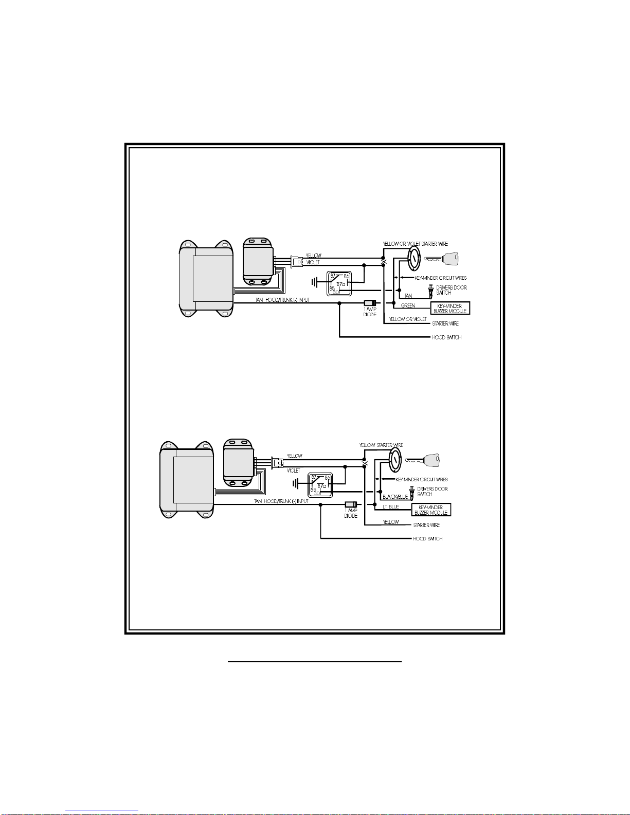
All vehicles have a "key in the ignition" reminder circuit (key minder) that will
sound a chime or buzzer while the key is in the ignition and the driver’s door
is open. The following diagrams will illustrate how to interface the key-minder
wires and a relay to prevent the vehicle from remote starting while the key is
in the ignition.
The wire color codes are subject to change. Check all wires with a
volt/ohmmeter. If you have any questions, please contact the Prime Technical
Support Department.
15
PrimeStart 650 Installation Manual
16
PrimeStart 650 Installation Manual
General Motors Sport Utility Vehicles, Trucks and
Column Shift Passenger Vehicles
Dodge Dakota Pickup Trucks
17
PrimeStart 650 Installation Manual
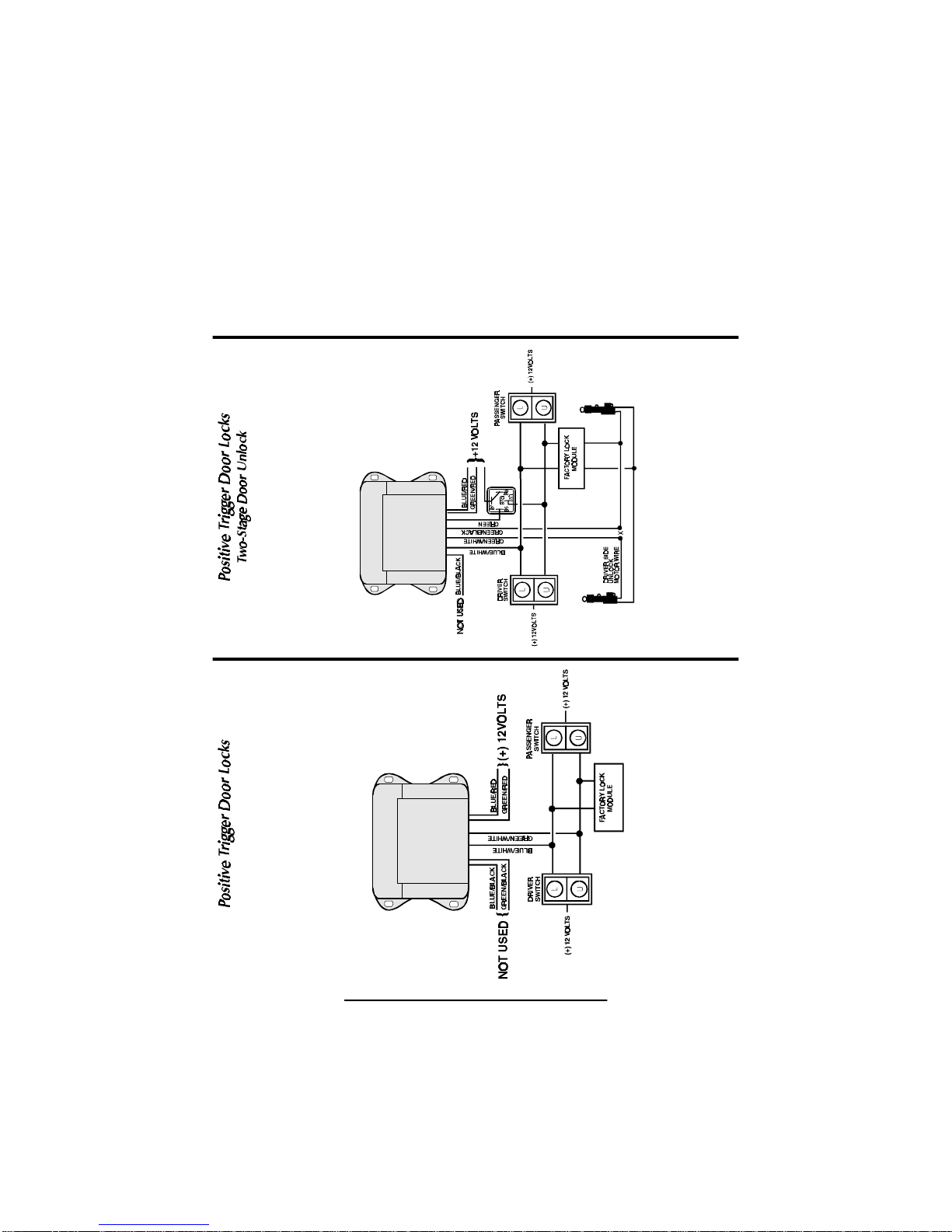
Door Lock/Unlock
The system has onboard door lock relays to lock and unlock all of the doors as
well as a two-stage unlock. The diagrams on pages 17-20 will illustrate
standard lock/unlock and two-stage unlock.

18
PrimeStart 650 Installation Manual
Table of contents
Other Prime Security Remote Starter manuals


Popular Remote Starter manuals by other brands


Clarke
Clarke Jumpstart 900 operating & maintenance manual

CrimeStopper
CrimeStopper PS01-G5 operating instructions

Ultra Start
Ultra Start 1500 SERIES installation guide

Bulldog Security
Bulldog Security RS1200 manual

Walmart
Walmart EverStart manual

AutoLoc
AutoLoc KL800 User guide and installation manual