Printekmobile VehiclePro 400 User manual

Drivers, User Manuals, and Software Utilities available @ www.printek.com
© 201 Printek LLC. A company. 1 17 Townline Road, Benton Harbor, MI 49022 PH: 269-92 -3200 FX: 888-211-3400 Part 7 64 Rev D
Printer Features
Loading Paper
Push paper door release, pull out drawer using the pull handles, drop in
paper roll and route through door as shown.
Note: Always use pull handles to open the drawer.
Printouts can be torn off in either direction.
Status Indications – Patterns & Meanings
Printer is Off.
Green Printer is On.*
Green
Printer is in Standby. (Will wake
on
receipt of data.)
Green
Printer is receiving data and/or printing,
or is in Setup mode.
Green/Orange
Without Alarm
Paper out or Paper Door is open.
Green/Orange
With Alarm
Paper out. (Load paper and press Paper
Feed to clear).
= Off = On = Slow Blink = Fast Blink
*Note: Automatic power on depends on printer installation.
Printer Self-Test and Configuration Printout
•Turn off printer power
•While pressing and holding Paper Feed button, turn on power
•Printer will make two quick beeps
•Release Paper Feed button and configuration page will print
VehiclePro 00
Quick Start Guide
Paper Door
Release
Status
Indicator
Tear Bar
Paper Feed
Button
PUSH
This guide provides information on the daily use of the VehiclePro 400 printer.
For additional information, please refer to the VehiclePro 400 Operator’s Manual.
Pull Handle
Pull Handle
Drivers, User Manuals, and Software Utilities available @ www.printek.com
© 201 Printek LLC. A company. 1 17 Townline Road, Benton Harbor, MI 49022 PH: 269-92 -3200 FX: 888-211-3400 Part 7 64 Rev D
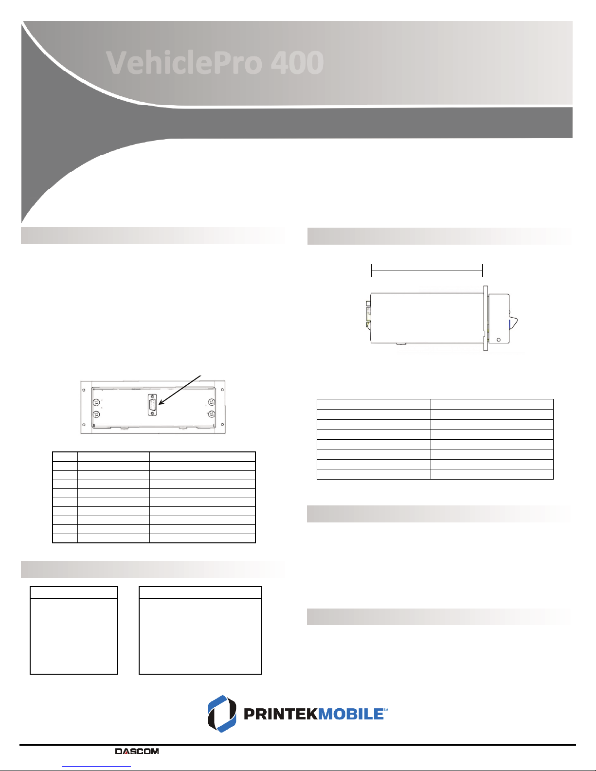
Cable Installation
Printek provides two optional cables to assist in installation – an RS-232
cable to be connected to a standard 9-pin serial connection on a PC, or a
USB cable. Each cable also provides a pigtail connection for power.
When using Printek cables, the Red labeled wire in the power cable may
be connected to a 12-24 VDC source and the Black wire is to be connected
to vehicle ground. The printer’s power input is internally fused, but may
be connected to a fused circuit that is capable of providing at least A.
If not using a Printek cable, the printer connections are defined in the
following table.
Data/Power Connector Pin Assignments
Pin
Signal Direction
Description
1 – NC
2 From Host Receive Data
3 From Printer Transmit Data
4 – NC
5 – Ground (Data & Power)
6 From Host Clear To Send
7 From Printer Request To Send
8 – Power (8-32 VDC)
9 – NC
Default Interface Settings
Printer Installation
To complete the installation, secure the data/power cable connector to
the back of the printer, insert the printer into the dash/console, and
fasten with four provided screws.
Vehicle Console Manufacturer* Mounting Plate Purchase Number
Havis, Inc. 93417
Lund Industries 93420
Gamber-Johnson 9342
D&R Electronics 93426
Precision Mounting Technologies
93427
Troy Products 93437
Jotto Desk 93437
*Console slot depth must meet or exceed 6 inches.
Check the Active Interface
•With printer powered on, push and hold Paper Feed button,
printer will beep
•Continue to hold Paper Feed button; after slight delay, printer
will beep again
•Release Paper Feed button and active interface settings page
will printer
Change the Active Interface
•With printer powered on, push and hold Paper Feed button,
printer will beep
•Continue to hold Paper Feed button; after slight delay, printer
will beep again, then make two quick beeps
•Release Paper Feed button after two quick beeps; power LED
will flash briefly to indicate change in active interface
Serial/USB
Bluetooth® (Optional)
Baud Rate: 7600
Data Bits: 8
Stop Bits: 1
Parity: None
RTS/CST: On
XON/XOFF: Off
ETX/ACLK: Off
Pairing Mode: Paired
Security: Off
Role Policy: Defer
Discoverability: On
Local Name: VP-SerialNumber
Pin: 0
VehiclePro 00
Installation
Data/Power Connector
Printer Depth
–
. ”


