PRINTEX P250 User manual

i
USER MANUAL
PRINTEX P250 THERMAL PRINTER
The contents of this document are subject to change without notice

2
CAUTIONS
^It’s grade A product, maybe it cause wireless jammer in the environment. In such
circumstances, need the user to do related steps.
COPYRIGHT
^Copied date: 2013 ^Version: 1.5
1...................................................................................................................................................................................
GENERAL DESCRIPTION.........................................................................................................................................1
1.1.......................................................................................................................................................................

3
Basic Specifications.......................................................................................................................................... 1
1.2......................................................................................................................................................................
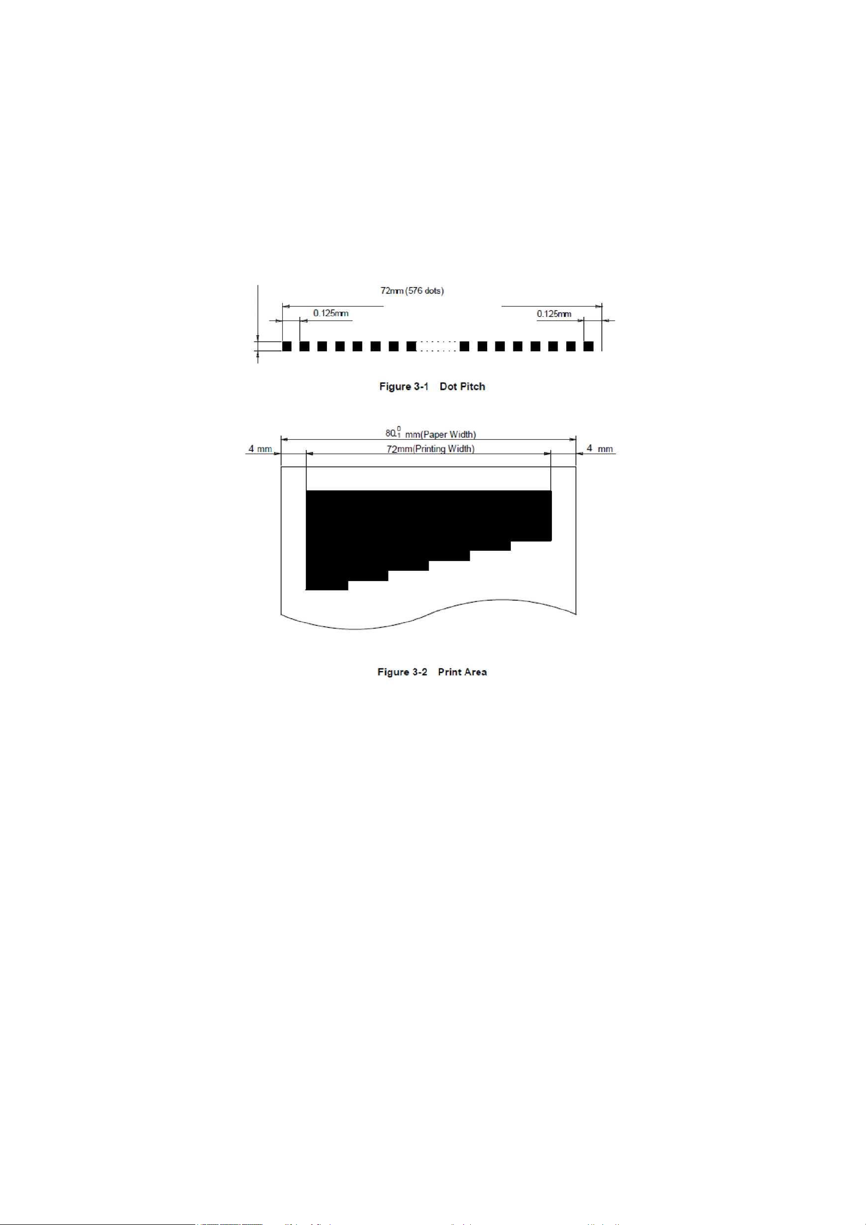
Printable Area................................................................................................................................................... 1
1.3......................................................................................................................................................................
Internal Buffer................................................................................................................................................... 3
1.4......................................................................................................................................................................
Printing Position and Tear off Position .............................................................................................................. 3
2 ..................................................................................................................................................................................
CONFIGURATION AND INSTALLATION................................................................................................................... 5
2.1......................................................................................................................................................................
Interface Specifications ................................................................................................................................... 5
2.1.1..........................................................................................................................................................
RS232 Serial Interface............................................................................................................................ 5
2.1.2..........................................................................................................................................................
IEEE 1284 Bidirectional Parallel Interface................................................................................................ 8
2.1.3..........................................................................................................................................................
Ethernet Interface...................................................................................................................................12
2.1.4..........................................................................................................................................................
USB Interface.........................................................................................................................................13
2.2......................................................................................................................................................................
Printer Installation............................................................................................................................................13
2.2 Power Connector..............................................................................................................................13
2.3......................................................................................................................................................................
Drawer Connector............................................................................................................................................14
3 ..................................................................................................................................................................................
FUNCTIONS.............................................................................................................................................................15
3.1......................................................................................................................................................................
List of Commands ...........................................................................................................................................15
3.2......................................................................................................................................................................
Power Button and Buttons ...............................................................................................................................17
3.2.1..........................................................................................................................................................
Power Button..........................................................................................................................................17
3.2.2..........................................................................................................................................................
Panel Button ..........................................................................................................................................17
3.3......................................................................................................................................................................
DIP Switch.......................................................................................................................................................17
3.3.1..........................................................................................................................................................
DIP Switch 1...........................................................................................................................................18
3.3.2..........................................................................................................................................................
DIP Switch 2...........................................................................................................................................19
3.4......................................................................................................................................................................
LED/Alarm.......................................................................................................................................................19
3.5......................................................................................................................................................................

4
Roll Paper Cover.............................................................................................................................................20
3. 6 Self-test....................................................................................................................................................20
3. 9 Error Processing.......................................................................................................................................21
3. 9. 1 Error Type ...................................................................................................................................21
3. 9. 2 Printer Operation When an Error Occurs .....................................................................................21
3. 10 Status Conditions....................................................................................................................................21
3.11 Buffer-Full Printing ..................................................................................................................................22
4...................................................................................................................................................................................
CASE SPECIFICATIONS ........................................................................................................................................23
4.1.......................................................................................................................................................................
External Dimensions and Mass ......................................................................................................................23
4.2.......................................................................................................................................................................
Color ..............................................................................................................................................................23
4.3.......................................................................................................................................................................
External Appearance ......................................................................................................................................23
5...................................................................................................................................................................................
COMMANDS............................................................................................................................................................24
5.1.......................................................................................................................................................................
Command Notation..........................................................................................................................................24
5.2.......................................................................................................................................................................
Explanation of Terms ......................................................................................................................................24
5.3.......................................................................................................................................................................
Detailed Explanation of Commands.................................................................................................................25
HT .........................................................................................................................................................25
LF ..........................................................................................................................................................25
CR .........................................................................................................................................................26
DLE EOT n ............................................................................................................................................26
DLE ENQ n ............................................................................................................................................28
ESC SO .................................................................................................................................................29
ESC DC4 ...............................................................................................................................................29
ESC ! n...................................................................................................................................................29
ESC $ nL nH..........................................................................................................................................30
ESC % n ................................................................................................................................................30
ESC & y cl c2 [x1 d1 ...d(y x x1)]...[xk d1...d(y xxk)]................................................................................31
ESC * m nL nH d1... dk ..........................................................................................................................33
ESC 2 ....................................................................................................................................................34
ESC 3 n..................................................................................................................................................35
ESC ? n..................................................................................................................................................35
ESC @...................................................................................................................................................35
ESC a n..................................................................................................................................................35
ESC D n1 . . . nk NUL.............................................................................................................................36
ESC i......................................................................................................................................................37
ESC J n..................................................................................................................................................37

5
ESC m................................................................................................................................................... 37
ESC \ nL nH .......................................................................................................................................... 37
ESC c 3 n.............................................................................................................................................. 38
ESC c 4 n.............................................................................................................................................. 38
ESC c 5 n.............................................................................................................................................. 39
ESC d n................................................................................................................................................. 39
ESC t n.................................................................................................................................................. 39
FS p n m................................................................................................................................................ 40
ESC P m n1 n2...................................................................................................................................... 41
FS q n [xL xH yL yH d1...dk]1...[xL xH yL yH d1...dk]n........................................................................... 41
FS p n m..........................................................................................................
GS ! n.................................................................................................................................................... 45
GS * x y d1..d( x y 8 )............................................................................................................................. 45
GS / m................................................................................................................................................... 46
GS : ...................................................................................................................................................... 47
GS H n .................................................................................................................................................. 47
GS I n.................................................................................................................................................... 48
GS L nL nH............................................................................................................................................ 49
®GS V m Vm n................................................................................................................ 49
GS W nL nH.......................................................................................................................................... 50
GS лr t m............................................................................................................................................... 51
GS f n.................................................................................................................................................... 51
GS h n................................................................................................................................................... 52
®G S k m dl . dk NUL ©G S k m n dl . dn....................................................................................... 52
GS r n.................................................................................................................................................... 55
GS v 0 m xL xH yL yH d1 ...dk............................................................................................. 56
GS w n .................................................................................................................................................. 57
GS ( k PL PH cn fn n1 n2(cn=49 ,fn=65)................................................................................................ 58
GS ( k pL pH cn fn n1 n2(cn=49 ,fn=69).................................................................................................58
GS ( k pL pH cn fn m d1 dk(cn=49 ,fn=80).............................................................................................59
GS ( k pL pH cn fn m (cn=49 ,fn=81)......................................................................................................59
GS ( k pL pH cn fn m (cn=49 ,fn=82)......................................................................................................59
5.5 Chinese Character Control Command ..................................................................................................60
FS ! n.....................................................................................................................................................60
FS & ......................................................................................................................................................61
FS..........................................................................................................................................................61
FS W n ..................................................................................................................................................61
APPENDIX A: MISCELLANEOUS NOTES...............................................................................................................62
APPENDIX B: ROLL PAPER SETUP .......................................................................................................................62
APPENDIX C: GET RIGHT FROM AUTOCUTTER ERROR.....................................................................................62
APPENDIX D: CLEAN THE PRINT HEAD................................................................................................................63
APPENDIX E: CODE128 BAR CODE.......................................................................................................................63


PRINTEX P250 User Manual
1
1 GENERAL DESCRIPTION
1.1 Basic Specifications
1.2 Printable Area
79.5±0.5mm The printable area of thermal paper is 72.2 ± 0.2 mm, There are 4.0 mm blank area left and right side,
as follows:
Specifications
Parameter
Printing Method
Line Thermal Printer
Printing Speed
150mm/S(Max)
Printing Density
8dot/mm
Printing Directions
Feed Paper Directions
Printing Width
79±0.5mm
Max diameter
83mm
Printing effective width
72mm
Paper Solve Method
Full cut/Partial cut
Line Width
3.75MM
Print head
Seiko CADP347
Thermal Print Head
100KM
Auto cutter
700,000 times
Interface
Serial/Parallel/Ethernet/USB
Character
ASCII/GB18030 Simplified Chinese /Traditional
Chinese/Multinational Chinese
Print character each line
24/48 21/42 16/58
Print character each line
48/48 42/42 32/58
Emulation
, ESC/POS® standard command protocol
Power Supply
DC24V/2A
During Operation
0°C~50°C 0~85% (humidity)
During Storage
-20°C~60°C 0~85% (humidity)
Dimension
142X154X144(WXLXH)
Weight
1300g(no paper roll)
Support OS
XP/2000/2003/Win7/Win 8

PRINTEX P250 User Manual
2
0.125mn
r

PRINTEX P250 User Manual
3
1.3 Internal Buffer
1.4 Printing Position and Tear off Position 1.5 ± 0.5mm
Full cut Partial cut
(Tab left at the center}
NOTE:
1. The values shown in the figures are typical values, the values may vary slightly as a result of the paper
slack or variations in the paper.
2. If the printer don’t work for a long time but installing the paper, the paper may be go to bad and fall on print
head; In such a case, before printing that must be fed paper 30mm firstly.
Receive Date Buffer Memory
4 KB
Macro Defined Buffer Memory
2 KB
NV Bit Image Buffer Memory
192KB

PRINTEX P250 User Manual
4
2 CONFIGURATION AND INSTALLATION
2.1 Interface Specifications
2.1.1 RS232 Serial Interface
2.1.1.1 Specifications
Data Transmission: Serial
Synchronization: Asynchronous
Handshaking: RTS/CTS orDTR/DSR or XON/XOFF control
Signal Levels: MARK = -3 to -15 V; Logic “1”/ OFF SPACE = +3
to +15 V; Logic “0”/ ON
Baud Rate: 115200, 38400, 19200, 9600bps
Data Word Length: 8 bits
Parity: None
Stop Bits: 1 bit or more
Connector (the side on the printer ): D-SUB25 male
NOTE: Handshaking, Baud rate and Parity decided by DIP Switch 1 setting. (refer to 3.3.1) the stop bits
fixed on 1.
Switching between online and offline:
The printer have not the online and offline switch.
The printer goes offline:
1) Between when the power is turned on (includes reset using the interface) and when the printer is get ready
to receive the data.
2) During the self-test.
3) When the cover is open.
4) During paper feeding pushing the paper feed button.
5) Stop printing when out of paper.
6) During macro executing standby status.
7) When an error have occurred.
2.1.1.2 Interface Pin Signal Definition
Interface connector terminal assignments and signal functions description as the following table:
Signal assignments and functions
Pin
NO.
Signal
Name
Signal
Direction
Function
2
RXD
Input
Receive data
3
TXD
Output
Receive data

PRINTEX P250 User Manual
5
Signal ground
Outpu
t
4
RTS
1) When DTR/DSR control is selected, The signal indicates whether the
printer is busy. SPACE indicates that the printer get ready to receive data, but
MARK indicates that the printer is busy. Changing the Memory Switch setting to
be used as a signal for printer busy.
2)
Printer Status
Memory SW1-3 Status
ON
OFF
Offlin
e
1.During the period from when the
power is turned on to when the
printer is ready to receive data.
BUSY
BUSY
2. During the self-test.
BUSY
BUSY
3. When the cover is open.
—
BUSY
4. During paper feeding using the
paper feed button.
—
BUSY
5. When the printer stops printingdue
to a paper-end.
—
BUSY
6. During macro executing standby
status.
—
BUSY
7. When an error has occurred.
—
BUSY
8. When the receive buffer becomes
full.(*1)
BUSY
BUSY
3) When XON/XOFF control is selected:
Signal indicates whether the printer is correctly connected and is ready to
receive data. SPACE indicates that the printer is ready to receive data.
The signal is always SPACE except in the following cases:
□During the period from when the power is turned on to when the printer
is ready to receive data
□During the self-test
SG
7
Signal assignments and functions (continued)
Pin No.
Sign
al
Nam
e
Signal
Direct
ion
Function
6
DSR
Input
This signal indicates whether the host computer can receive data. SPACE
indicates that the host computer can receive data, and MARK indicats the host
computer can't receive the data.
When DTR/DSR control is selected, the printer transmits data after confirming this
signal (except when transmitting data by DLE EOT and GS a) .
When XON/XOFF control is selected, the printer does not check this signal.
Changing the DIP switch setting enables this signal to be used as a

PRINTEX P250 User Manual
6
Serial interface socket case
Can use the below signal relational cables.
9 pin serial pin definition 25 pin serial pin definition
reset signal for the printer.
20
DTR
Outpu
t
Same as RTS signal
6
DSR
Input
This signal indicates whether the host computer can receive data. SPACE
indicates that the host computer can receive data, and MARK indicats the host
computer can't receive the data.
When DTR/DSR control is selected, the printer transmits data after confirming this
signal (except when transmitting data by DLE EOT and GS a) .
When XON/XOFF control is selected, the printer does not check this signal.
XON/XOFF Transmit time
When XON/XOFF be selected, The printer transmits the following XON or XOFF signal. The difference of transmit
time decided by DIP switch setting.
XON/XOFF Transmit time
Printer status
DIP Switch
ON
OFF
XON
® Turn the power on, the printer enter into online ®When
“buffer area is full” of the receive buffer area be removed ®
When the printer from offline to online ® Recover from the error
by DLE ENQ 1 or DLE ENQ 2 command
Transmit
Transmit
Transmit
Transmit
Transmit
Transmit
XOFF
@ When receive buffer area becomes full ®When the printer
from online to offline
Transmit
Transmit
Transmit
Notes: □XON code is <11>H, XOFF code is <13>H„
□In the case of □ , When the receive buffer area is full, XON will not transmit.
□In the case of ©, When the receive buffer area is full, XOFF will not transmit.a
9 pin RS-232 serial (DB9)
25 pin RS-232 serial (DB25)
Pin
No.
Simp
lified
Function
Pin
No.
Simp
lified
Function
1
CD
Carrier Detect
8
CD
Carrier Detect
2
RXD
Receive
3
RXD
Receive
3
TXD
Transmit
2
TXD
Transmit

PRINTEX P250 User Manual
7
DIP Switch 1-3 is ON
1) When the printer occure error, open the cover, when out of paper or feed paper, the printer only
stop working but not busy status.
2) When DIP Switch is ON and handshaking signal is effective, check the printer status by GS a and ASB
command. In this status, the default of GS a parameter n is 2. The printer transmit the printer status
automatically, it decided by online/offline status.
3) When use DLE EOT, should be confirm that the receive buffer area is not full enough.
•For example, when the printer is busy, the host can not transmit the data:
When receive buffer area full to make printer busy, if occur error, can not use DLE EOT
•If the printer is busy, the host can transmit the data:
When transmite bit image data, if receive buffer area full and process bit image date that transmit DLE
EOT at the same time that will be as bit image data.
When receive buffer area full, maybe lose the data if transmit.
For example: When use 4KB receive buffer area, after transmitting each lie data, check theprinter status by GS r
1. Transmit one line data to make the receive buffer is not full enough.
2.1.2 IEEE 1284 Bidirectional Parallel Interface
2.1.2.1 Specifications
Data Transmission: 8-bit parallel
Synchronization: Externally supplied nStrobe signals
Handshaking: nAck and busy signals
Signal Level: TTL compatible
Connector : ADS-B36BLFDR176 (Honda) or equivalent (IEEE 1284 Type B)
Switching between online and offline
The printer is not equipped with any online/offline switch. The printer is placed into offline status in
either of the followings:
1) When the power is turened on or until the printer becomes ready for data transmission
afterit is initialized by the reset signal (nlnit) from the interface.
2) During the self-test.
3) When the cover is open.
4) During paper feeding using the paper fedd button.
5) When the printer stops printing due to a paper-end(in cases when empty paper supply is
detected by either the paper roll end detector or the paper roll near-end detector with a printing halt
4
DTR
Data Terminal Ready
20
DTR
Data Terminal Ready
5
GND
Ground
7
GND
Ground
6
DSR
Data Set Ready
6
DSR
Data Set Ready
7
RTS
Request To Send
4
RTS
Request To Send
8
CTS
Clear To Send
5
CTS
Clear To Send
9
RI
Ring Indicator
22
RI
Ring Indicator

PRINTEX P250 User Manual
8
due to paper shortage enabled by ESC c 4).
6) During macro executing standby status.
7) When an error has occurred.
Reverse data mode
The status data transmission from the printer to the host is processed in the nibble or byte mode. NOTE: At
present, reverse data transmission by nibble.
□ Description
This mode allows data transmission from the asynchronous printer under the control by the host.
Data transmissions in the Nibble mode are made via the existing control lines in units of
four bits. In the byte mode, data transmissions are processed by making the eight-bit data lines
bidirectional.
The both modes fall to process concurrently with the compatibility mode, thereby causing half duplex
transmission.
2.1.2.2 Interface Pin Signal Defination
Interface Pin Assignments for Each Mode
Compatibility
Mode
Pin
Source
4-bits Mode
1
Host
nStrobe
HostClk
2
Host/Ptr
Data0(LSB)
Data0(LSB)
3
Host/Ptr
Data1
Data1
4
Host/Ptr
Data2
Data2
5
Host/Ptr
Data3
Data3
6
Host/Ptr
Data4
Data4
7
Host/Ptr
Data5
Data5
8
Host/Ptr
Data6
Data6
9
Host/Ptr
Data7(MSB)
Data7(MSB)
10
Printer
nAck
PtrClk
11
Printer
Busy
PtrBusy/Data3, 7
12
Printer
Perror
AckDataReq/Data2, 6
13
Printer
Select
Xflag/Data1, 5
14
Host
nAutoFd
HostBusy
15
NC
ND
16
GND
GND
17
FG
FG
18
Printer
Logic-H
Logic-H
19
GND
GND
20
GND
GND
21
GND
GND
22
GND
GND

PRINTEX P250 User Manual
9
*NC: Not Connected ND: Not Defined
NOTES: 1. A prefix “n” to signal names refer to low level active signals.
2. To the host provided with none of the signal lines listed above, both-way communication fails.
3. For interfacing, signal lines shall use twisted pair cables with the return sides connected to signal ground
level.
4. Interfacing conditions shall be all based on the TTL level to meet the following characteristics In addition,
both rise and fall time of each signal shall be 0.5|js or less.
5. Data transmission shall not ignore the signal n Ack or Busy. An attempt to transmit data with signal, nAck
or Busy, ignored can cause data lose. (Data transmission for the printer shall be made after verifying the
nAck signal or while the Busy signal is at the low level.)
6. Interface cables shall be as min required short in length as possible.
Electrical Characteristics
23
GND
GND
24
GND
GND
25
GND
GND
26
GND
GND
27
GND
GND
28
GND
GND
29
GND
GND
30
GND
GND
31
Host
nInit
nInit
32
Printer
nFault
nDataAvail/Data0, 4
33
GND
ND
34
Printer
DK_STATUS
ND
35
Printer
+5V
ND
36
Host
nSelectIn
1284-Active
DC Characteristics (Except Logic- H, + 5 V signals)
Characteristics
Symbol
Specifications
Conditions
Min
Max
Output High Voltage
Voh
*2.4 V
5.5 V
*Ioh=0.32 mA
Output Low Voltage
Vol
-0.5 V
*0.4 V
*Iol=-12 mA
Output High Current
Ioh
0.32 mA
-
Voh=2.4 V
Output Low Current
IoL
-12 mA
-
Vol=0.4 V
Input High Voltage
Vih
2.0 V
-
Input Low Voltage
Vil
-
0.8 V
Input High Current
Iih
-
-0.32 mA
Vih=2.0 V
Input Low Current
IlL
-
12 mA
Vil=0.8 V
Logic - H Signal Sender Characteristics
Characteristics
Symbol
Specifications
Conditions
Min
Max
Output High Voltage
Voh
3.0 V
5.5 V
While the
Output Low Voltage
Vol
-
2.0 V
power is OFF

PRINTEX P250 User Manual
10
Reset printer by parallel
To enable the printer reset by nlnit signal (PIN 31) in compatibility mode. Set nlnit signal by SWITCH DIP. To
enable the printer reset, meet the following signal timing.
The signal is ignored when #36 nSelectln /1284-Active is high in reverse mode.
□DC characteristic TTL Level
□AC characteristic
Min reset pluse width: TRS 50^s (min)
NOTE: The prefix “n” named active-low
Reception of status from the printer through the bidirectional parallel interface
In the bidirectional parallel interface specifications, the printer status transmission is available by
using the both-way communication facility in the Nibble/Byte Modes in accordance with the IEEE 1284.
In this case, different from in the RS-232 serial interface specifications, the real-time interruptions from the
printer to the host are disabled and thus precautions must be taken to the followings:
1) Allowable capacity of the printer internal buffer is 99 bytes (except ASB status), The status signals
exceeding this capacity will be discarded, To prevent possible loss of status, the host shall be ready for data
acception (Reverse Mode).
+5 V Signal Sender Characteristics
Characteristics
Symbol
Specifications
Conditions
Min
Max
Output High Voltage
*Ioh=0.32 mA
Output Low Voltage
Voh
*2.4 V
5.5 V
While the power is
Output High Current
Vol
-
OFF
Output Low Current
Ioh
-
0.32 mA
Voh=2.4 V
Iol
-
While the power is OFF
** No guarantee is offered to VOL and IOL while the power is OFF.
Parallel Data Receiving Timing Parallel Interface Signal Timing Figure as follows(Compatibility Mode):

PRINTEX P250 User Manual
11
2) When ASB is used, the host is preferably in the wait state for data acception (ReverseIdle Mode).When this
state is not available, the host shall enter the Reverse Mode to always monitor the presence of data.
3) When ASB is used, preference shall be given to the ASB status for transmission over the other status
signals. Once one ASB conditions changed, all ready to send ASB conditions from last time that need to send
together, then sending the latest ASB conditions.
2.1.3 Ethernet Interface
2.1.3. Ilnterface Specifications
Ethernet Type: Standard Ethernet (10M)
TCP/IP agreement: ETHERNET, ARP, IP, TCMP, IGMP, UDP, TCP, HTTP, DHCP;
Connector Type: RJ45 (as table)
2.1.3.2 Interface connection
1. Default IP address “192.168.1.6”, IP port “9100”, checked by self-test list;
2. Link the printer to LAN, open IE and input the IP address of the printer, default “192.168.1.6”, Carriage return to
log in. After modifying the related information, then “Reset”;
3. If printing by Windows driver, install PRINTEX P250 driver. After installing driver, find installed PRINTEX P250
driver in “printer and fax”. Choose attribute, then “Port”-“Add port”-choose “Standard TCP/IP Port”, operate
according its prompt.
4. Change driver to this port, test through printing test page.
Notes:
1. Default IP port 9100, normal condition that needn't change;
2. Add “Standard TCP/IP Port”, when choosing “Device type”, to choose “Standard”.
2.1.3.3 Interface Pin Signal Definition
2.1.4 USB Interface
2.1.4.1 Interface Specifications
Connector Type: Type B female interfaceB
Communication Agreement: USB2.0
2.1.4.1Interface connection
Pin NO.
Signal Name
Signal Source
1
TX+
Tranceive Data+ (Send signa+)
2
TX-
Tranceive Data+-(Send signa-)
3
RX+
Receive Data+ (Receive signal+)
4
N/C
Not connected(Blank)
5
N/C
Not connected(Blank)
6
RX-
Receive Data-(Receive signal-)
7
N/C
Not connected(Blank)
8
N/C
Not connected(Blank)

PRINTEX P250 User Manual
12
1. Connect printer to PC, and turn the power on;
2.Install Windows driver(PRINTEX P250), At the page of ’’Printer and fax”, find the installed driver ”PRINTEX P250”,
right click and open the page of ’Attribute”, will have ”USB000n” at ”Port”(May be n is 1,2,3 or anothers, decided by
printer USB port), change the printer driver to this port and print test page;
Notes:
When use USB port,if turn the printer power off for a long time, printer driver (PRINTEX P250) will be went off
automatically, this moment driver can not print normally, right click to cancel offline print;
2.1.4.3 Interface Pin Signal Defination
Pin definition:
2.2 Printer Installation
2.2 Power Connector
NOTE: To guarantee the normal operation to the printer. Please use the standard power from our company.
Pin Definition:
Pin NO.
Function
Color
Definition
1
V Bus
Red
Power +5V
2
Data-
White
Data-
3
Data+
Green
Data+
4
GND
Black
Ground
Pin NO.
Signal
1
+24
2
GND
3
NC

PRINTEX P250 User Manual
13
SHELL
F. G
2.3 Drawer Connector
PRINTEX P250 used RJ-11 6 connector, as follows:
Pin Definition as the following table:
Pin NO.
Signal Ground
Direction
1
Frame GND
—
2
Drawer kick-out drive signal 1
Output
3
Drawer open/close signal
Input
4
+24V
-
5
Drawer kick-out drive signal 1
Output
6
Signal GND
-

PRINTEX P250 User Manual
14
3 FUNCTIONS
3.1 List of Commands
Command
Name
Command Type
Standard
Mode
Executive
Set
HT
Horizontal tab
□
□
LF
Print and line feed
□
□
CR
Print and carriage return
□
□
DLE EOT
Transmit real-time status
□
□
DLE ENQ
Send real-time request to printer
□
□
ESC !
Select print modes
□
□
ESC %
Select/cancel user-defined character
set
□
□
ESC &
Define user-defined characters
□
□
ESC *
Select bit-image mode
□
□
ESC 2
Select default line spacing
□
□
ESC 3
Set line spacing
□
□
ESC ?
Cancel user-defined characters
□
□
ESC @
Initialize printer
□
□
□
ESC a
Select justification
□
□
ESC D
Set horizontal tab positions
□
□
ESC i
Full cut
□
□
ESC J
Print and feed paper
□
□
ESC m
Partial cut
□
□
ESC V
Turn 90D clockwise rotation mode
on/off
□
□
ESC c 5
Enable/disable panel butons
□
□
ESC d
Print and feed n lines
□
□
ESC t
Select character code table
□
□
ESC {
Turn upside-down print mode on/off
□
(□ )
ESC P
Cash draw command
□
□
FS p
Print NV bit image
□
□
FS q
Define NV bit image
□
(□ )
GS !
Set character size
□
□
GS
Define downloaded bit image
□
□
GS ( A
Execute test print
□
□
GS ( B
Set printer parameter
□
□
GS /
Print downloaded bit image
□
•
GS :
Start/end macro definition
□
□
□
GS B
Turn white/black reverse print mode
on/off
□
□
Table of contents