Printronix P5000 Series User manual

User’s Manual
General Purpose Input/Output (GPIO)
Manager and Module


Product Warranty
Printronix warrants that the Products furnished under this Agreement shall be
free from defects in material and workmanship for a period of one year from
the date of shipment from the Printronix facility. This warranty is applicable
only if the products have had normal utilization within the published
specifications as modified from time to time, have been maintained in
accordance with recommended procedures with Printronix approved parts,
and have not been modified or altered in a manner not approved by
Printronix.
For printers sold within the area in which Purchaser normally provides field
service:
For all printers the Purchaser will provide the end-user with a 90-day
on-site warranty. Any printer or part therein found defective within one
year of original shipping date from a Printronix facility shall be returned to
Printronix and be repaired or replaced at the option and expense of
Printronix. Purchaser shall pay shipping cost to the Printronix facility and
Printronix will return the item(s) at its expense.
For printers sold outside the area, within the Continental United States, in
which Purchaser normally provides field service:
Any printer found defective within 90 days from the date of shipment to
the end user will be repaired at the end user’s location. If the end user is
located within 100 miles of an Authorized Service Provider’s location,
warranty service will be performed at no charge. If the end user is located
more than 100 miles from an Authorized Service Provider’s location,
travel time and expenses in excess of 100 miles will be billed to the end
user at current rates or the printer may be shipped to the nearest
Authorized Service Center for repair. If the end user elects to ship the
printer for warranty repair, the end user shall pay the shipping cost to the
Authorized Service Center and the printer will be returned at Printronix’
expense.
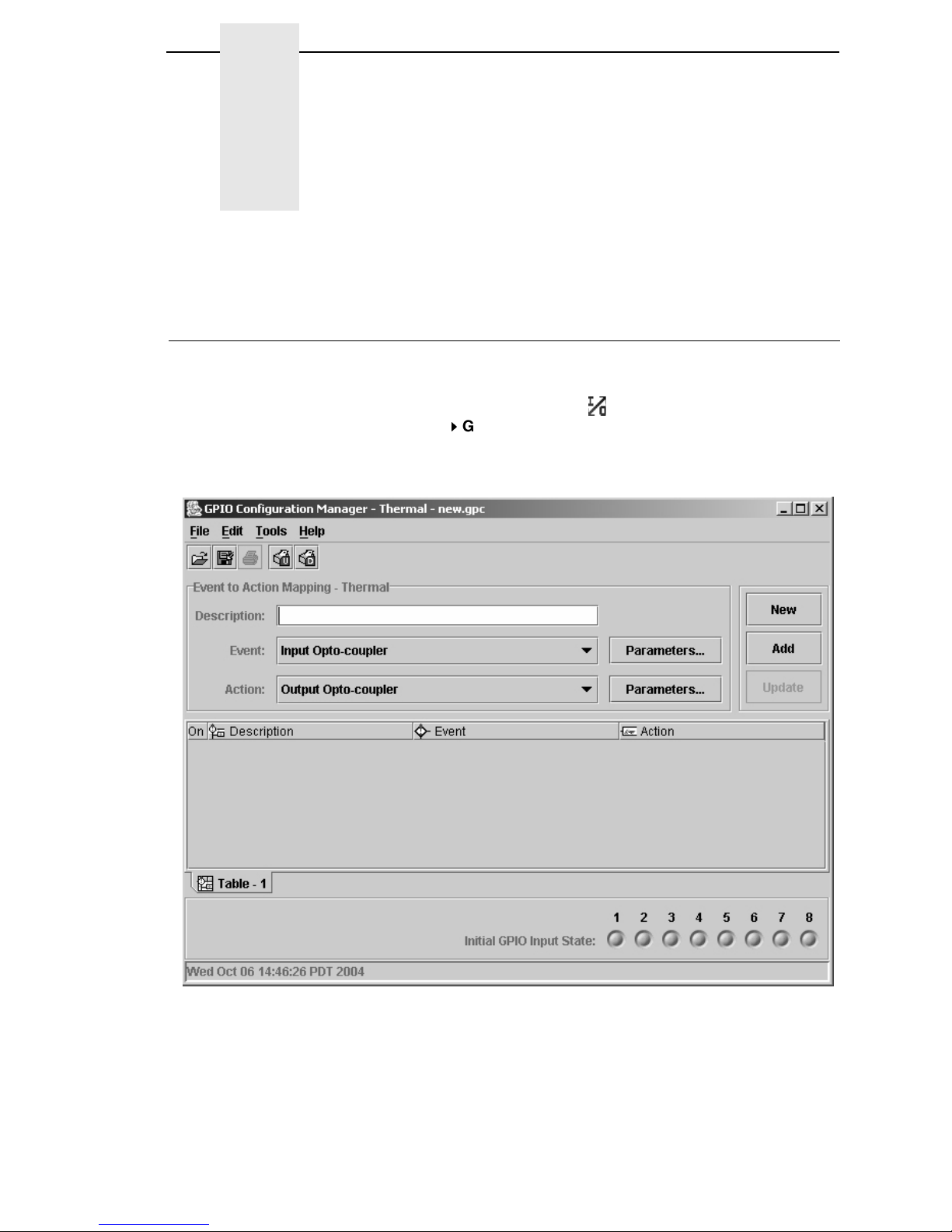
The Products may be equipped with a general purpose input/output circuit
board and corresponding pin connection (GPIO) which allow the Purchaser’s
or end user’s printer to function as a controller in a computer system.
Printronix publishes the specifications associated with GPIO and the pin
connection and warrants that the printer’s input and output parameters at the
pin connection conform to those specifications. Except as expressly
warranted, GPIO is sold on an “as is” basis. There are no other warranties
whatsoever, express or implied, concerning GPIO.
Purchaser’s remedies are expressly limited to Printronix’ obligations as stated
above, and in no event shall Printronix be held liable for any incidental or
consequential damages or loss of use, or other commercial loss, however
occasioned.
The warranties set forth in this article and the obligations and liabilities
thereunder are in lieu or, and the purchaser hereby waives, all implied
guarantees and warrantees, including without limitation, any warranty of
merchantibility or fitness for a particular purpose. In no event shall Printronix
be held liable for any incidental or consequential damages or loss of use, or
other commercial loss, however occasioned.

Notice of Copyright
This document contains proprietary information protected by copyright. No
part of this document may be reproduced, copied, translated, or incorporated
in any other material in any form or by any means, whether manual, graphic,
electronic, mechanical, or otherwise, without the written consent of Printronix,
Inc.
All non-Printronix registered and/or unregistered trademarks used throughout
this manual are the sole property of their respective owners.
COPYRIGHT 2003, 2005, PRINTRONIX, INC.
All rights reserved.

1 Introduction ........................................................... 7
Overview................................................................................................ 7
Events and Actions ................................................................................ 7
The Hardware ........................................................................................ 7
2 The GPIO Manager............................................... 9
Overview................................................................................................ 9
The Menus .................................................................................... 10
The Entry Fields ............................................................................ 11
Password ...................................................................................... 12
Events and Actions ....................................................................... 13
Entry Control Buttons........................................................................... 23
Multiple Actions ............................................................................. 24
The ON Flag.................................................................................. 25
The Initial State ............................................................................. 25
Data Fields........................................................................................... 26
Data Field Events And Actions...................................................... 27
Data Field Events .......................................................................... 29
Defining Reports .................................................................................. 31
Sections ........................................................................................ 33
Reports.......................................................................................... 35
Using Reports ............................................................................... 36
3 Mapping .............................................................. 37
Download Mapping Tables .................................................................. 37
Pre-Loaded Table ................................................................................ 37
Mapping Examples .............................................................................. 38
PPI-1 ............................................................................................. 39
PPI-2 ............................................................................................. 41
Printronix T3000 and Equivalent Printers...................................... 44
Other Competitors ......................................................................... 46
Indicator Lights Example ............................................................... 48
Simple Applicator Example ........................................................... 50
Protected Printer Example ............................................................ 51
Panel Selected Label Printing ....................................................... 52
Table of Contents

Table of Contents
A Technical Information.......................................... 55
Opto-couplers ...................................................................................... 55
Relays.................................................................................................. 56
Voltages............................................................................................... 56
I/O Connector ...................................................................................... 56
B Basic GPIO Schematic Diagram ......................... 59
C Electrical Inputs And Outputs.............................. 61
GPIO Opto-coupled Input Circuit......................................................... 61
GPIO Opto-coupled Output Circuit ...................................................... 61

7
1Introduction
Overview
This document describes the Printronix General Purpose Input/Output (GPIO)
function available for the Printronix T5000 series Thermal printers and the
P5000 series Line Matrix printers.
GPIO is both hardware and software. The hardware is the I/O board to be
mounted in the printer,and the software is the GPIO Manager which is part of
the Printronix Remote Management Software Advanced Tool Kit. The GPIO
hardware is a printed circuit board containing optically isolated inputs and
outputs as well as relays. The GPIO software is both a printer resident GPIO
event parser and a PC-based GPIO manager that allows the user to define
how the general purpose I/O hardware should behave for the given
application.
Events and Actions
The operation of GPIO is based on Events and Actions. Events can be either
printer internal such as “paper out” or “print complete,” or they can be printer
external such as “opto-coupler 1 active.” Actions are the result of (or the
reaction to) an event and can be printer internal such as “paper feed” or
printer external such as “relay 1 active” or “reply to host” where data is
transmitted over the serial, parallel, or network interface. You can also define
a number of events to be acted upon without the GPIO card installed in the
printer, which allows the printer to be adapted for the application in use.
The Hardware
The GPIO hardware (see Figure 1 on page 8) consists of 16 opto-couplers,
4 SPDT relays, a real time clock, and the logic required to connect this
hardware into the printing system.
NOTE: Although the GPIO hardware includes a real time clock, it will not be
described in this manual. Its programming and use are strongly
related to PGL and equivalent languages, and those manuals
document the real time clock.

8
Chapter 1 The Hardware
Eight of the 16 opto-couplers are used as isolated inputs; these are the
connections on which the external events happen. The remaining eight
opto-couplers and the four SPDT relays are used as isolated outputs. Each of
these outputs can be activated as an action in response to some event. The
board is connected into the printing system through the printer’s expansion
port.
None of the inputs or outputs is connected to any voltage source; it is the
user’s responsibility to make those connections. A separately fused
5-volt and a separately fused 24-volt are available on the 50 pin connector in
which all inputs and outputs are terminated.
Figure 1. GPIO Hardware
GPIO
Logic
Outputs 1 . . 8
R
T
C
System Interface
Relay 1 . . 4
Inputs 1 . . 8

9
2The GPIO Manager
Overview
The GPIO Manager is part of the Advanced Tool Kit (ATK) version of the
Printronix Remote Management Software (RMS).
To access the GPIO Manager, click the icon in the RMS/ATK toolbar or
select Applications
GPIO Manager. The screen in Figure 2 displays. The
fields on this screen is described in detail in the following pages.
Figure 2. The GPIO Configuration Manager

10
Chapter 2 Overview
The Menus
The toolbars are like any other toolbar; they allow the usual handling of files
and text.
Figure 3. The GPIO Configuration Manager Toolbar
File
The File menu allows you to create, open, or save a new or existing I/O
configuration. The Print option is currently disabled. The Properties option
allows you to select the type of printer, Thermal or Impact, that the I/O
configuration is to be created for. Password allows you to attach a password
to a mapping table.
Edit
The Edit menu allows you to define, delete, and rename mapping tables. You
can also define data fields and reports to customize mapping table.
Tools
The Tools menu allows you to upload or download an I/O configuration. You
also have the option to select the last selected upload printer or the last
selected download printer. This option allows you to quickly select a
previously uploaded or downloaded printer without having to go to the RMS
printer database for your selection.
Help
The Help menu allows you to open the User Guide of this program if the guide
is stored in the correct directory on the user’s system. If it cannot be found, an
error message displays. The About option provides basic information about
the GPIO Configuration Manager as seen in the startup splash screen.

The Entry Fields
11
The Entry Fields
Figure 4. The Event To Action Mapping Fields
Setting the criteria for mapping tables takes place here (Figure 4). The
Description
field allows you can enter a descriptive name to indicate the use
of the event and its related action.
NOTE: The window header indicates which printer the mapping table is
created.
The Event field allows you to select the event on which some action is to be
taken. Table 1 on page 13 lists the events currently available in the software.
Figure 5. Setting Event Parameters
The Event Parameters button allows you to select additional conditions
related to the event (Figure 5).

12
Chapter 2 Overview
Figure 6. Setting Action Parameters
The Action Parameters button allows you to select all possible actions that
are programmed to take place as a result of some event (Figure 6).
Password
Figure 7. Setting Passwords
A password can be attached to the mapping table (also called the GPIO
Configuration file). This password will be stored, in the GPIO configuration
file, in the printer’s flash memory. Uploading of a password-protected file is
possible, but before any operation can be performed on or with this file, you
must enter the password.

Events and Actions
13
Events and Actions
The Events
Table 1 lists the available events and the related parameters. Each of the
events will be described separately. Parameters on events are valid for the
Input Opto-Couplers, Panel Key Pressed events, ODV events, Printer Error
and Warning events, and PAA events.
Table 1: Events And Parameters
Events Printer Type Parameters
Input Opto-Coupler Opto-Coupler Number (1..8), Active, Inactive
Printer Powered Up n.a
Printer Online n.a
Printer Offline n.a
Printer Local n.a
Power Save Mode Active n.a
Power Save Mode Cleared n.a
Start Data Processing n.a
End Data Processing n.a
Printer Buffers Empty n.a
Label Pending Thermal n.a
Start Printing n.a
Start Paper Move Impact n.a
Label Printed Thermal n.a
Label Present Thermal n.a
Label Taken Thermal n.a
Job Printed n.a
End Paper Move Impact n.a
Printer Error Thermal Any, Paper Out, Paper Jam, Ribbon Out,
TOF Detect Fault, Head Open, RFID Tag
Failed, RFID Max Retry
Impact Any, Platen Open Paper Jam, Paper Empty,
Ribbon Stall, Stacker Fault, Stacker Full
Printer Warning Thermal Any, Ribbon Low
Panel Key Event Thermal Printer Type related Key Description

14
Chapter 2 Overview
Event Descriptions
•Input Opto-Couplers
For external input signals. You can specify the number of the
opto-coupler to view and the level on which the event is seen as active.
Clicking the opto-coupler symbol selects the active state.
Figure 8. Setting the Opto-coupler Number and State
•Printer Powered Up
This event is delayed until the moment the printer reaches the Powered-
up-online or Powered-up-offline state. The delay is required so the printer
can finish its power-on reset cycle before any reaction to an event is
generated.
•Printer Online
When the printer goes online by pressing the Pause key, the action
related to this event is taken.
•Printer Offline
When the printer goes offline by pressing the Pause key or the menu key,
or if there is any other reason that causes the printer to switch offline, the
action related to this event is taken.
•Printer Local
This event happens when the printer is paused by pressing the Pause
key. The printer accepts data from the host and parses this data until its
buffers are full. No printing occurs. The print engine is offline, but the
printer’s data processing unit is still online.
ODV Events Thermal Missing barcode, Quality error – Any or a
specific one, All ODV errors cleared
PAA Event Event identifier
Data Field Changed Data Field, Condition, Type, Value
Table 1: Events And Parameters

Events and Actions
15
•Power Save Mode Active
This event signals the moment when the printer enters Power Save
Mode.
•Power Save Mode Cleared
Opposite of the Power Save Mode Active, this mode signals the moment
the printer becomes active.
•Start Data Processing
This event signals the start of the processing of received data. This is not
the same as the Start Printing event.
•End Data Processing
This event signals the end of the data processing cycle. This is not the
same as the end printing event.
•Buffers Empty
This event takes place as soon as the print buffers are emptied.
•Label Pending
This event generates when the printer is in Local mode (i.e., the print
engine is temporarily stopped) and all incoming data has been processed.
•Start Printing
This event happens when the printer starts printing. The printer starts
printing when all data processing is done, there is actual data to print, and
the printer is no longer in local mode. The event will not happen on “paper
moves without print.”
•Start Paper Move
This event is only available in the Impact Printer mode of the GPIO
Manager. It indicates the beginning of the paper motion.
•Label Printed
This event occurs when a number of labels stored in the printer have
finished printing. If the labels print as a single job without any wait time,
the event will be a short pulse. If the printer is placed in local mode and
the labels are printed using the
print next label
action, the event will
happen once for each label.
•Label Present
In label peel off applications, this event happens when the label present
sensor detects a label in position (ready for application). It may be used to
signal the availability of a label to an applicator system.
•Label Taken
This event is generated when the label is taken from its ready to apply
position. It can be used to tell the host that a new label can be printed.
•Job Printed
This even is generated if everything in the buffer has been printed.

16
Chapter 2 Overview
•End Paper Move
This event is only available in the Impact Printer mode of the GPIO
Manager. It indicates the end of the paper motion.
•Printer Error/Printer Warning
These events signal printer errors and warnings. They allow selection of
the error or warning that is seen as the event. Impact printers do not
support warnings.
Figure 9. Setting Errors for an Event Parameter
To select the Printer Error event, click the Event drop-down menu and
select Printer Error as the event parameter. Click the Parameters button
to the right of the event then click the Any box to uncheck the setting. A
list of errors (or warnings) is now available for selection. From the Error
drop-down menu, select the required parameter (Figure 9).
The Set state identifies the event when the problem happens. The
Cleared state specifies the event when the problem is solved.

Events and Actions
17
•Panel Key Event
This is an event in which the operator panel keys are parameters. The
event allows you to change the function of some of the keys or to disable
selective keys. For example, if the panel key event with JOB SELECT/
DECREMENT(-) results in the action “Do Nothing,” the menu key is
disabled.
Figure 10. Setting Panel Key Event Parameters
•ODV Events
This selection allows you to react to output from the Online Data
Validator. The parameters allow you to program GPIO to act when there
is no barcode, when there are barcode errors, or when all ODV errors are
cleared. This event is not available for Impact printers.
Figure 11. ODV Event Parameters

18
Chapter 2 Overview
•PAA Event
PAA generates an event on a user-specified input string. A large number
(32000+) of PAA events can be generated through the use of an
identifier.
Figure 12. PAA Event Parameters
•Data Field Changed
This event happens if the value in a given data field changes. Certain
conditions are applicable. See “Data Fields” on page 26.
The Actions
The Action field allows you to specify which action should be linked (or
mapped) to the selected event. Table 2 lists all possible actions and related
parameters.
Table 2. Event Actions and Parameters
Actions Printer
Type Parameters
Output Opto-Coupler Opto-Coupler Number (1..8), Activate, Deactivate,
Pulse
Output Relay Relay Number (1..4), Activate, Deactivate, Pulse
Printer Online n.a
Printer Offline n.a
On/Offline Switch n.a
Clear Buffer n.a
Pulse Printing n.a
Start Printing n.a
Print Next Label Thermal n.a
Reprint Last Printed Label Thermal n.a

Events and Actions
19
Form Feed n.a
Move Paper TOF, Specified Distance Forward/Backward
Cut Once Thermal n.a
Delete Page n.a
Lock Operator Panel n.a
Unlock Operator Panel n.a
Keyhandling Consume
Disable GPIO Events n.a
Enable GPIO Events n.a
Reply to Host Data to be Transmitted, Interface to be used
Wait Time to Wait in mSeconds
PAA Control: Reset CST
Select Mapping Table Name of Table to switch to
Data Field Destination, Operator, Source, Type
Send Report Name, Destination, Duration
Table 2. Event Actions and Parameters
Actions Printer
Type Parameters

20
Chapter 2 Overview
Action Descriptions
•Output Opto-Couplers
The opto-coupler number to activate can be specified as well as the level
(or state) required for this output. You can select the state by clicking the
opto-coupler symbol. If the Pulse parameter is selected, the pulse
duration can be set in increments of 50 msec between 50 and
2,147,483,647 msec. This allows pulses up to 24.8 days in duration. If
Repeated Pulse is selected, the pulse will repeat with a 50% duty cycle
until deactivated.
Figure 13. Setting Ouput Opto-coupler Action Parameters
•Output Relay
The relay number to activate can be specified as well as the level (or
state) required for this output. You can select the state by clicking the
relay symbol. Pulsed behavior for the relays is equivalent to the pulsed
behavior of the opto-coupled outputs.
Figure 14. Output Relay Settings
Other manuals for P5000 Series
7
This manual suits for next models
1
Table of contents
Other Printronix Printer Accessories manuals