Prio Expert MO Series User manual

Prio®Expert
User’s Guide
MO530
MO520
MO510
MO___
Reverse Osmosis
Filtration System
(Storage Tank,
Main Filtration Unit Set)

2
Before operating this appliance, please read the instructions carefully. You
may want to save this guide for your future reference. Failure to follow the
instructions or meet the operating requirements may lead to the product’s
failure, malfunction, property damage or personal injury.
Safety Warning
■Do not place the storage tank near the sources of heat, radiators, etc.
■Keep the appliance out of reach of pets or other animals.
■Do not use the appliance if operating requirements such as water tempera-
ture/water pressure/electrical supply, etc. are not met. There may be other
local regulations to comply with.
■Do not use the appliance with water that is microbiologically unsafe or of
unknown quality without adequate disinfection before or aer the system.
■Do not use the waste water produced by the appliance for drinking or cooking.
■Never store or operate the appliance in direct sunlight.
■This appliance is not intended for use by persons (including children) with
reduced physical, sensory or mental capabilities, or lack of experience and
knowledge, unless they have been given supervision or instruction con-
cerning use of the appliance by a person responsible for their safety.
■Children should be supervised to ensure that they do not play with the ap-
pliance.
■At the end of its life, the appliance should be disposed o in an appropriate
manner.
Disposal
Old appliances still contain many recyclable materials. Therefore, please take
used unit to your retailer or recycling center so that it can be recycled.

3
Description
Congratulations on your purchase of the Prio® Expert R.O. ltration system! With proper
installation and maintenance, it will provide you with high quality drinking water for many
years.
This R.O. system removes odor and most harmful substances such as heavy metal ions and
total dissolved solids from tap water making it tasty, fresh and vital.
Please familiarize yourself with the general concept behind the product and main modes of
operation.
Key Features:
■Clean and safe drinking water right in your home. No need to transport and dispose of
bottled water any more.
■Factory-preinstalled lters and membrane for faster and easier setup.
■Filters and membrane quick-change housings for easy regular maintenance.
■Compact and beautiful design.
■Quick ttings for easy tube connections and change of lters.

4
How It Works:
This Prio® Expert reverse osmosis system is a multi-stage automatic ltration machine.
Reverse Оsmosis (R.O.) is a water purication technology that uses a semipermeable mem-
brane to remove ions, molecules and larger particles from drinking water. R.O. can remove
many types of dissolved and suspended species from water, including bacteria, and is used in
both industrial processes and the production of potable water.
Water supply is done through the inlet valve, ltered water is rst stored in the water tank and
then delivered through the faucet, and waste water is drained through the drain saddle. Detailed
connection scheme is shown on the following charts.
Inlet valve:
An adapter ball valve is included to be installed into the cold water supply line to feed water
to the ltration unit inlet.

5
Faucet:
Designer faucet for ltered water is included and usually mounted on the sink deck or counter-
top for dispensing the clean, ltered water from the ltered water storage tank.
Water Storage Tank:
Air pressurized storage tank is used for ltered water storage.
Drain saddle:
Fits a standard 1.5” diameter drain pipe to drain the waste water from the drain outlet of the
ltration unit.
Pre-Filters:
The main R.O. unit has two pre-lters: sediment pre-lter on the rst stage and activated
carbon pre-lter on the second stage. They provide initial ltration of the water and protect
the following thin lm composite R.O. membrane from dirt and aggressive chemicals such as
chlorine oen found in tap water.
R.O. Membrane:
The third and main stage of the ltration is R.O. membrane. It is “semi-permeable”, which
means that it allows water to pass through but prevents dissolved particles from passing
through. It splits the feed water into two streams: clean water goes to the post-lter and then
onto the tank and faucet. Waste water with rejected particles goes down the drain.
Post-Filter:
Last stage of ltration is an activated carbon post-lter and/or remineralization for ne con-
ditioning and keeping the extra freshness of your water.
Specication
Operating Requirements:
■Minimum supply water pressure1: 30 psi (0.2 MPa)
■Maximum supply water pressure: 80 psi (0.55 MPa)
■Minimum water temperature: 41 oF (5 oC)
■Optimal water temperature: 59–77 oF (15–25 oC)
■Maximum water temperature: 95 oF (35 oC) / up to 105 oF (40.5 oC) short-term
■Ambient air temperature: 41–105 oF (5–40.5 oC)
■Water source: tap water supply, chlorinated or non-chlorinated, bacteriologically safe
■Supply water pH range: 4.0-11.0
■Supply water turbidity: < 1 NTU
■Supply water components: Hardness (CaCO3) <180 mg/L (<10.5 gpg), Iron <0.1 mg/L,
Manganese <0.05 mg/L, Hydrogen Sulde 0.00 mg/L
■Maximum supply water TDS: 1000 ppm
■Indoor use only.
■Tubing: ¼”
1If below 40 psi, a booster pump may be required. X845 Pump Bot is then recommended.

6
Performance:
Performance of the appliance such as ltered water delivery rate, rejection rate, etc. is highly
dependent on local conditions (inlet water pressure, temperature, TDS and degree of contam-
ination, tank air pressure, etc.) and R.O. system use pattern. Actual performance may vary.
■Filtered water production rating: 75 gpd (270 lpd) maximum
■Filtered water delivery rate (from the tank), typical: 0.27–0.74 gpm (1–2.8 l/min)
■Membrane rejection rate1, typical: 90%
■Recovery rate (system eciency2), typical: 15%
■Drain water ow restrictor: 300 cc (ml/min) nominal, up to 360 cc in working mode.
■Tank Storage Capacity (Total Volume): up to 2.5G (4.0G)3
■Tank full rell time4, typical: 70-120 min
Weight and Size:
R.O. ltration unit:
Size (WDH), body only, excluding protrusions: 13.46 x 3.35 x 14.80” (342 x 85 x 376 mm)
Weight, without water and tubing: 8.8 lbs (4.0 kg)
Storage tank:
Tank model No. X842G X852G
Storage Capacity (Total Volume) up to 2.0G (3.2G) up to 2.5G (4.0G)
Size (WxDxH), body only,
excluding protrusions
9.8 x 9.8 x 13.6”
(250 x 250 x 347 mm)
10.55 x 10.55 x 14.90”
(268 x 268 x 378 mm)
Weight, without water and tubing 4.7 lbs (2.1 kg) 6.0 lbs (2.7 kg)
Warranty:
1 year worldwide limited warranty (+ local regulations if applicable)
Package Contents:
(1) The R.O. ltration unit with installed l-
ters (K871, K870, K866, K875 for MO510;
K871, K870, K866, K880 for MO520,
MO530)
(1) Storage tank (X842G model for MO510,
MO520; X852G model for MO530)
(1) Universal worldwide adapter ball valve
(G1/2” - G3/8” - UNEF 9/16”-24 - JG 1/4”)
(1) Teon tape roll
(1) Faucet
(1) Drain saddle
(1) Wrench
(1) ¼” tank valve
(26 / 8 m) Water tubing ¼”
(1) ¼” x ¼” union check valve
(2) ¼” x ¼” x ¼” union tee tting
User’s guide
1 For all dissolved solids combined as measured by TDS or conductivity meter.
2 Eciency rating means the percentage of the inuent water to the system that is available to the user as
reverse osmosis treated water under operating conditions that approximate typical daily usage.
3 Depending on current SKU scope of supply.
4 Depending on supply water pressure.

7
Installation
Notes:
1. Shut o the cold water supply under the sink or the location where the system will be
installed. If the existing valve is inoperable, the water supply to the house must be shut
o. Then, relieve the water pressure by opening the cold water tap. Do not connect the
system to hot water source.
2. Depending on your plumbing system and sink/countertop type you may need to use tools
like variable speed drill, drill bits, screw driver, wrench, etc. You may want to ask a profes-
sional service provider such as certied plumber to install the inlet valve adapter, faucet,
and drain saddle to assure a trouble-free setup.
3. During installation you will need to cut the supplied ¼” tubing into segments as needed.
Use your utility knife for that or similar tool. See the following charts to determine the
connection scheme and length of hoses necessary. You may need to purchase extra tubing
for far-reaching or other corner case installations.
4. With initial operation, check for leaks. If a leak is observed, verify that the tubing is
pushed into the quick tting far enough to seal the tubing against the O-ring and that the
tubing was cut at 90°.
8
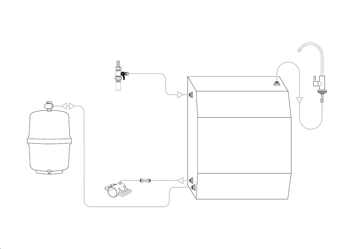
drain
saddle
check valve
tank
waste water outlet
permeate outlet to the tank
to drain or waste water
collection container
filtered
water
faucet
filtration unit inlet
inlet valve
(optional)
General connection scheme:

9
IMPORTANT: Cut Tubing At 90° to Ensure a
Watertight Seal:
Units Placement Guide:
R.O. ltration unit
Remember this unit must be serviced at regular intervals. Therefore it should be reasonably
accessible (for changing lters or membrane, etc.).
To Connect the Tubing to a Fitting:
1. Remove the lock if present (not present in self-locking ttings).
2. Push. Insert the tube rmly until full stop.
3. Pull the collet back slightly.
4. Replace the lock (if present).
To Disconnect the Tubing:
1. Remove the lock if present (not present in self-locking ttings).
2. Push the collet and hold.
3. Pull the tubing out.
4. Replace the lock (if present).
1
4
3
2
1
3
ut
1
4
2
3
No skewed cut!
4
3
2
1
10
Installation Steps:
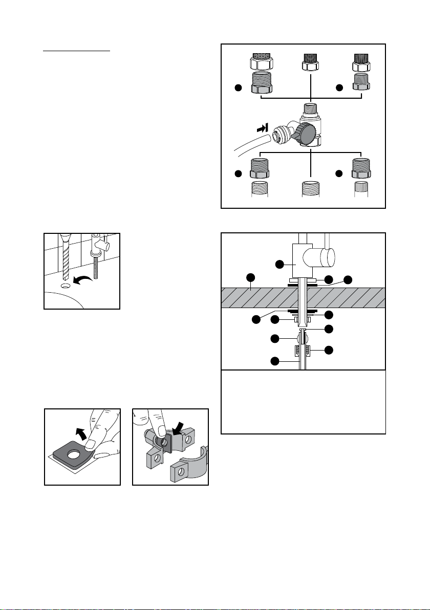
1. Install adapter ball valve (included) to the
cold water supply.
Use some Teon or plumbers sealing tape to
prevent leaks. Use three included threaded
adapters to make dierent connection con-
gurations (see chart for details).
2. Create ½” hole for the ltered water faucet and install it.
Tip: If you have a soap dispenser or a water
sprayer in an existing hole you may remove it
and use its hole for the ltered water
faucet.
3. Install drain saddle.
t
The square foam gasket with a circle cut out must be applied to the inside of the drain sad-
dle. Remove sticky tape backing and stick to the drain saddle as shown.
1
23
4
56
7
8
9
10
11
1. Faucet
2. Chrome washer
3. Black rubber washer
4. Countertop or
sink deck
5. Black washer
6. Lock washer
7. Lock nut
8. Insert
9. Sleeve
10. Compression nut
11. Tubing
UNEF 9/16”-24
G3/8” G1/2”
G1/2”
Adapter Adapter
UNEF 9/16”-24
UNEF 9/16”-24
G3/8”
G1/2”
1
Adapter
1
Adapter
2
3

11
mount drain
saddle here
never
mount
here
never mount
here
Drill a ¼” hole in the drain pipe
above the trap and on the ver-
tical or horizontal tail piece. Lo-
cate the drain connection away
from the garbage disposal to
prevent potential contamination
and system fouling.
4. Install water storage tank and mount tank valve.
Tank is a clean water storage container.
Never place the tank in direct sunlight or
near the sources of heat. It’s recommended
to have the tank been installed near the R.O.
ltration unit and the faucet.
Mount tank valve on the inlet-outlet port of
the tank. Use some Teon or plumbers seal-
ing tape to prevent leak.
5. Remove gags and connect tubes as follows. See the connection chart for details.
■Insert water supply tubing from inlet valve adapter into the “inlet”
tting of the R.O. ltration unit.
■Connect with the tubing the “tank” outlet tting of the R.O. ltration
unit with the tank valve tting.
■Insert the waste tubing from the “waste water” outlet tting of the
R.O. ltration unit into the drain saddle (through the optional union
check valve on the way) or to a waste water collection container. Install
the check valve with the arrow in the direction of ow.
■Insert ltered water tubing from the “faucet” outlet tting of the R.O. ltration unit into the fau-
cet using insert, sleeve and compression nut. See faucet installation chart for deta ls.
3/
m un dra n
n t

12
Initial Washing:
Aer installation it is recommended to perform the initial washing of the system. For this:
■shut o the tank
valve
■open cold water
supply valve
■open the inlet
valve
■open the ltered
water faucet
15-30 min
■wait for water to arrive at the faucet (it may take a while, especially rst time, water foam
and air may be going out of the system); wait for 15-30 minutes for more or less steady
weak ow from the faucet.
■shut o the faucet, and open the tank valve.
■wait for tank full rell then drain the tank by opening the faucet.
■repeat tank rell and drain once again by shutting o and opening the faucet, then shut o
the faucet and wait for tank rell with clean water.
■your system is ready for use.

13
Regular Use
To get clean water just open the ltered water faucet. The ltered water stored in the tank
will be delivered. R.O. water ltration system will rell the tank gradually even aer you shut
o the faucet. The system will shut o automatically when the tank will become full again.
Please note that R.O. membrane needs up to 50 hours of active operation before reaching
peak performance in terms of water ow, recovery and rejection rates. The delivery rate and
available amount of ltered water depend on how full the tank is. You may need to shut o the
faucet and wait for the tank rell to get more water.
Tips:
■You may install the optional union tee tting to the tubing line prior to the ltered water
faucet to get another line of clean water going to the other point-of-use (such as a sink in
a bathroom or ice maker in your fridge).
■Operating the system using soened feed water greatly reduces the chances of membrane
failure and prolongs lters and membrane service life.
Changing Filters and Membrane
This R.O. system contains the replaceable components critical to the eciency of the system.
Replacement of a component should be with one of identical specications, as dened by the
manufacturer, to assure the same eciency and contaminant reduction performance.
To reduce the risk of water leakage or ooding, and to ensure optimal R.O. system performance:
■Change the disposable pre-lters every 6 months or sooner if you observe a noticeable
reduction in water production rate.
■Change the disposable post-lter every 12 months or sooner if you observe a noticeable
reduction in water ow or production rate.
■Change the disposable R.O. membrane every 24 months or sooner if you observe a notice-
able reduction in water production rate.
Failure to replace the disposable lters & membrane at recommended intervals may lead to re-
duced system performance and cracks in the lter housings, causing water leakage or ooding.
Please note the capacity of the lters and membrane is limited. Their service life depends on
the degree of contamination of the water supply and system usage. All terms apply to normal
household use. Actual performance may vary. You may need to change lters or the mem-
brane sooner than indicated if you notice chlorine or other tastes or smells, etc. Manufacturer
recommends a TDS test every six months.
Replacement Filters:
■K871 (sediment pre-lter)
■K870 (activated carbon pre-lter)
■K866 (R.O. membrane)
■K880 (activated carbon post-lter and
conditioner)
■K875 (granular activated carbon post-lter)
Optional post-lters which can also be used
instead of K875/K880:
■K873 (granular activated carbon with
schungite natural mineral post-lter)
■K870 carbon block pre-lter may also be
used as a post-lter.

14
To prevent leakage or cracks and ensure the safety of operation and top performance do not
disassemble the lters or try to regenerate them.
To change lter(s) or membrane:
time
times
■shut-o the inlet
valve
■shut o the tank
valve
■relieve the water
pressure by open-
ing the ltered
water faucet
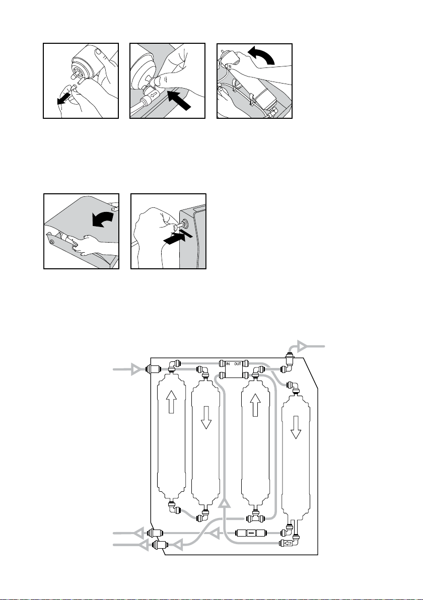
■remove the R.O. ltration unit from its place
for easier access (disconnect external tubes
if necessary) and open the unit’s cover
■locate the lter (membrane) to be
changed, disconnect its inlet and outlet
ttings and remove it
■take new lter (membrane) and install it in the place of the removed one observing the
water ow direction arrow on its label and restoring the connections (see the internal con-
nections chart for details)
15-30 min
or
Note: Remove and change back one lter at
a time, one aer another. Do not remove all
lters at once to avoid mixing up the tubes.
15
Note: For a pre- or post-lter you only need to connect its inlet and outlet. For the membrane
you have to connect the third outlet – to the waste water line. This outlet is located o the
center of the membrane housing. Elbow check valve tting (with the arrow) has to be con-
nected to the central (permeate) outlet of the membrane housing.
■close the cover, reconnect the external tubes and place the unit back in its place
Aer you nished changing lters or the membrane follow the “initial washing” procedure as
described above. With initial operation, check for leaks. If a leak is observed, verify that the
tube or branch pipe of the lter/membrane housing is pushed into the quick tting far enough
to seal the tube against the O-ring and that the tubing was cut at 90o.
membrane K866
pre-filter K871
pre-filter K870
post-filter K875/K880
waste water outlet
permeate (to tank)
R.O. unit inlet
to the faucet
R.O Filtration Unit Internal Connections Chart

16
Water Storage Tank Service
Water storage tank may require air repres-
surizing if you notice low water delivery rate
even with full tank.
The storage tank has the bladder inside
which separates air from water. On the lower
side of the tank there is the air valve con-
nected to the compressed air chamber. The
top water inlet-outlet port (where the tank
valve is mounted) is connected to the pure
water chamber. When you open the faucet,
the compressed air would compress the
bladder to force the water out of the tank.
In an empty tank, air pressure in the air
chamber should be 5-8 psi (0.35-0.55 bar). If
pressure drops below this threshold you may
notice low delivery rate of pure water from
the tank.
To recharge the tank:
■Shut o the water supply valve.
■Drain the tank by opening the faucet to al-
low water to run until it stops.
■Check to see if there is still water in the
storage tank. If the tank feels heavy,
that means you need to recharge the
air chamber and continue the following
steps. If the tank feels light, that means
it is not time yet to recharge the tank at
this moment.
■Locate the air valve. Use bicycle tire air
pump to pump air into the tank through
this valve. Keep the faucet open while
pumping air so that all water inside the
tank can be purged.
■Aer all water has been drained from the
tank, use an air pressure gauge to check
the tank pressure. The tank should have
5-8 psi (0.35-0.55 bar) of pressure when
it’s empty. Add or purge air if necessary.
■Open the water supply valve and close the
faucet to allow relling of the tank.
Please note that storage tank service life is
limited. Take into consideration that it stores
water of room temperature and is not ster-
ile, thus it may become the source of a sec-
ondary contamination over time. Unpleas-
ant smell or taste may appear in the water.
If changing the post-lter doesn’t solve the
problem your tank may require retirement
and your system needs a new tank.
Prio, Prio logo are the trademarks of DWT Deutsche Wassertechnologien GmbH, Germany.
As used herein, ® denotes registered trademark status in Germany only.
Copyright © DWT Deutsche Wassertechnologien GmbH, Germany, 2014, 2019
This manual suits for next models
3
Table of contents
Other Prio Water Filtration System manuals


Popular Water Filtration System manuals by other brands


Pure-Pro
Pure-Pro EC106R user manual

Pure-Pro
Pure-Pro M100-P user manual

Fillmaster Systems
Fillmaster Systems Fillmaster Filtration Installation instructions and service guide

Bluebird
Bluebird Pure Diamond user manual

USFilter
USFilter RO-2127 Installation and operating insctructions

WaterTech
WaterTech Reionator Pro RX10 owner's manual